Center Vent Pod Replacement
on the 1987 300D (W124)
by sixto
2/21/09
87 300D Center Vent Pod Replacement
Here's my take on replacing an 87 300D center vent pod. I just replaced a perfectly good pod, but everyone says to replace the pods when the dash is off. Like a lemming, here's how I did it -
0) You'll note through the progression of pictures that the heater core fins take a beating through this job. The heater core remains intact despite liberal use of screwdrivers and other sharp objects. I strongly recommend cardboard or plastic card to protect the heater core while replacing the center vent pod.
1) I don't mean to pull a Haynes on you but you have to remove the dash. No two ways about that. I have a DIY on that here:
Dashboard Replacement
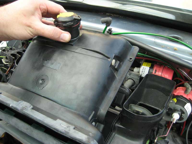
2.0) Remove the top cover of the airbox.
With the dash off, the black plastic thing smack in the center of the dash area with a little turret on it is the ACC airbox. The cover has to come off so you can replace the diverter and center vent pods. The cover is held by 2 clips just under the duct that feeds the center pods, a screw beside each duct that feeds the defroster vents and 2 screws against the bulkhead by the clips that hold the ACC vacuum lines. The bulkhead edge screws will make you curse MB engineers!
Here's the cover off the airbox -

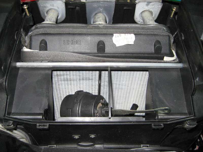
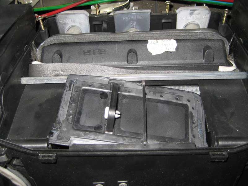
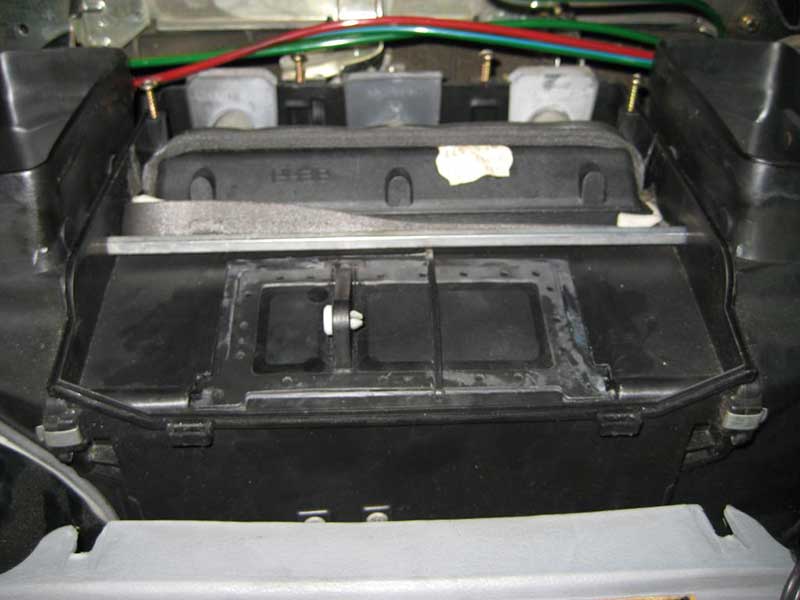
Here's the airbox minus the cover -
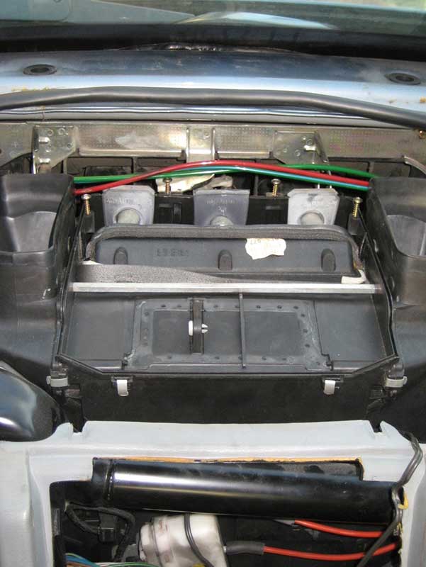
Since the dash is off at this stage I'll assume the switch panel and ACC controls are off the console.
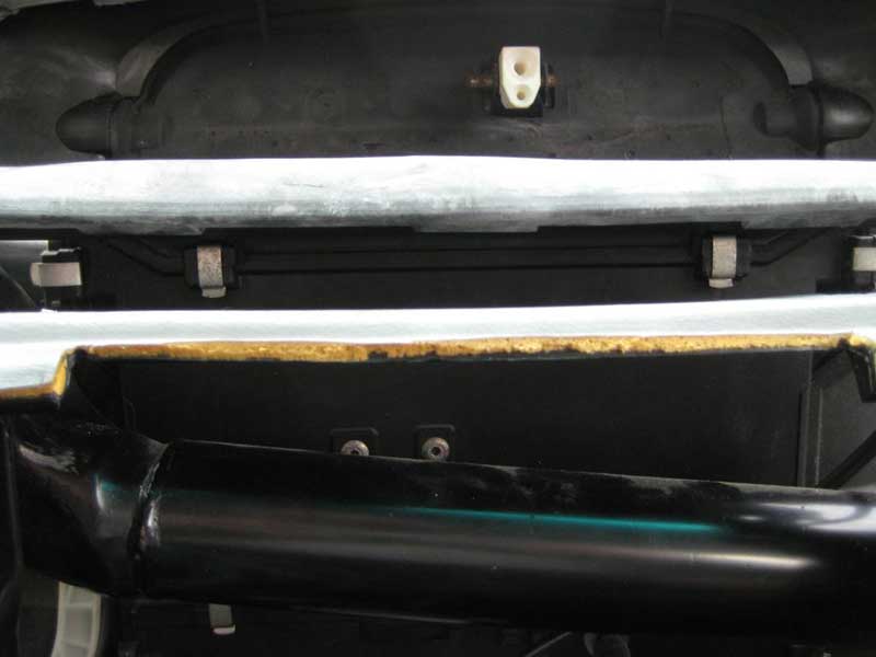
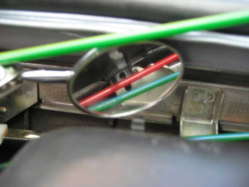
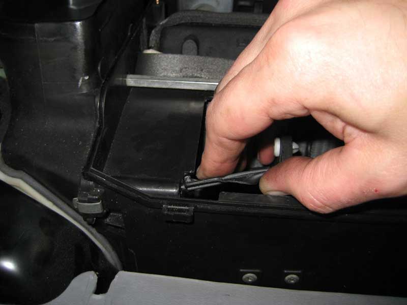
2.1) Remove the 2 clips holding the... first let's set orientation. It's confusing to talk about the radio in the car because the front, the part containing the controls, faces aft and the back, the part containing the connections, faces forward. I'll try to stick to calling the aft end the console end and the forward end the bulkhead end if for no other reason than because my other writeups follow that convention. Back to work. There are 2 clips on the console end. The clips hang from the cover and clip onto the main section of the airbox. It's hard to get a good picture of the clips but they're easy to see and reach.
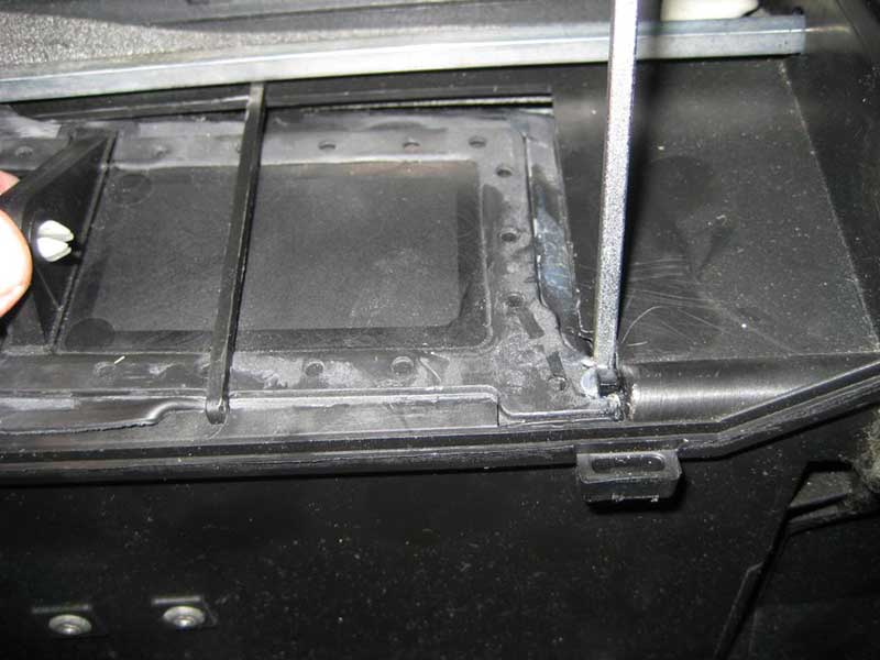
The 2 clips to remove are between the top ledge of the console and the bottom of the center vent duct. The 2 clips hang vertically. Don't touch the 2 clips that hang horizontally outboard of the vertical clips. Note that this picture doesn't provide the sense of depth involved -
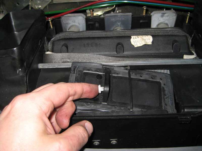
I'll preview this installation picture to show the clip partially attached. In reality it's easier to remove the clips with your fingers. Simply pull the tab at the bottom of the clip towards you to release the bottom attachment then lift the clip so the tap at the top comes out of the pocket on the airbox cover. I dropped these clips numerous times and each time was able to fish it out of the depths of hell where the radio is. Sometimes the radio had to come out. The clips can be reclaimed with a magnet (whew!) -

2.2) Remove 1 screw along each side of the airbox cover. The screws are next to the defroster ducts, the big ducts facing upwards. The screws take a Philips screwdriver. The screws can be reclaimed by a magnet but they might fall somewhere a magnetized tool doesn't reach -
2.3) Along the bulkhead edge, the cover has two rows of clips to hold the ACC vacuum lines. The left clip holds the supply line and a line for each nipple of the driver side recirc pod. The right clip holds in addition the line for the diverter pod atop the airbox cover. I don't think the clip position is relevant. At least I hope it isn't Push the lines off the clips with your fingers -
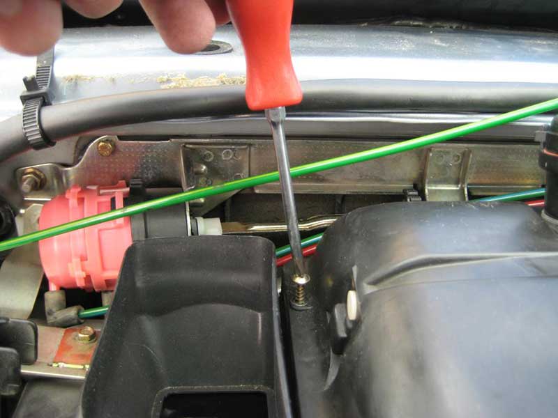
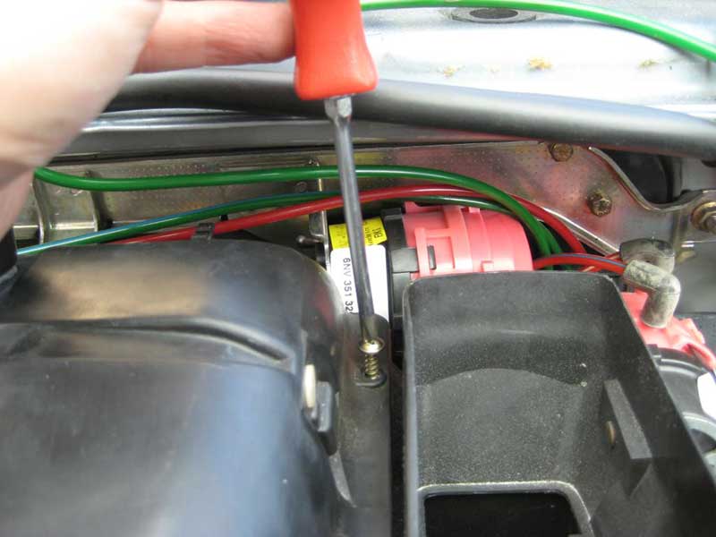
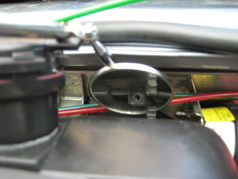
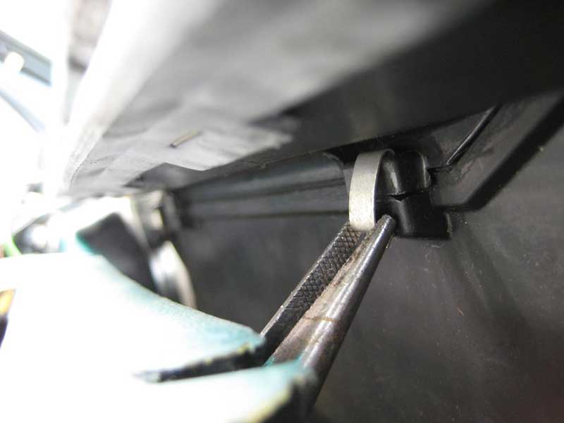
2.4) Now the fun begins. There are 2 screws along the bulkhead edge of the airbox cover under the ridge that supports the windshield. Seems like a perfect place to use clips but MB engineers went with screws. It was difficult enough to navigate a Philips screwdriver into place while holding a mirror, try it while taking a picture! use the best screwdriver you have because it's going to contact the screw at about a 15* angle. You might try a screwdriver tip with a breaker bar or a u-joint or flexible drive -
2.5) This should probably have been done earlier but pull the vacuum line off the diverter pod atop the airbox cover. This is the best picture I have. The diverter pod is the cyliner on the left end of the picture -
2.6) Lift the airbox cover up and off the airbox -
2.7) So the diverter and center vent pods have been addressed and the airbox cover is ready to go back onto the airbox. Haynes time! I don't have a picture with sufficient detail but there's a lip along the bottom of the cover that fits into a slot along the top of the airbox, but you see the slot along the right edge of the airbox under the lifted cover in step 2.6. The fit in my car was quite precise so the cover dropped right into place. Keep this in mind if the clip anchors and screw holes don't align.
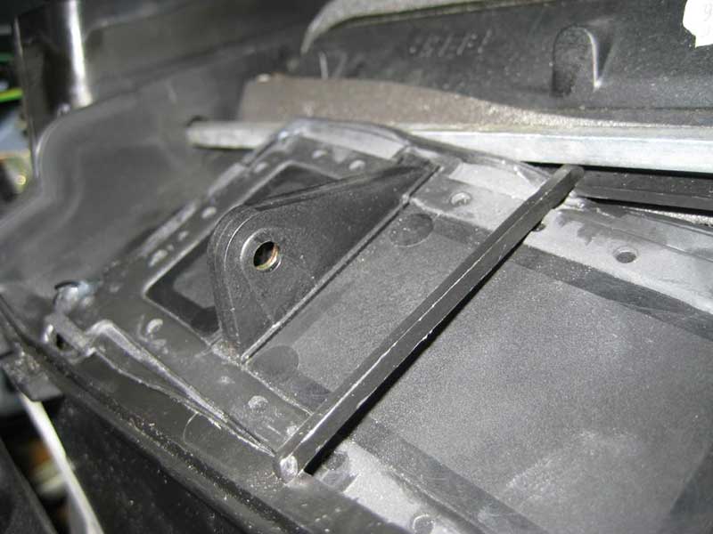
2.8) I started with the screws along the bulkhead edge. Make sure the holes are aligned then do whatever magic it takes to get the screws into their holes without falling out while you reach for a screwdriver. In my car, the bracket by the driver side screw hole doesn't move. That's it's natural relation to the airbox -
2.9) Then the screws along the sides. Same pictures as in step 2.2.
2.10) Then the clips along the console edge. Not so easy to do with fingers, I found. I used longnose pliers to hang the clips in place then pressed them into place with my fingers. The dash crossbar makes it difficult to get the driver side clip in place. The passenger side clip is easier -
2.11) Get the vacuum lines back on the clips (step 2.3) and attach the vacuum line to the diverter pod (step 2.5).
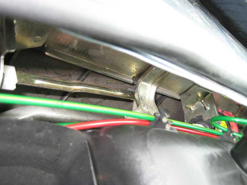
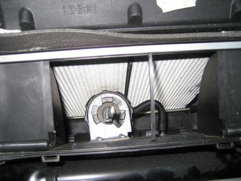
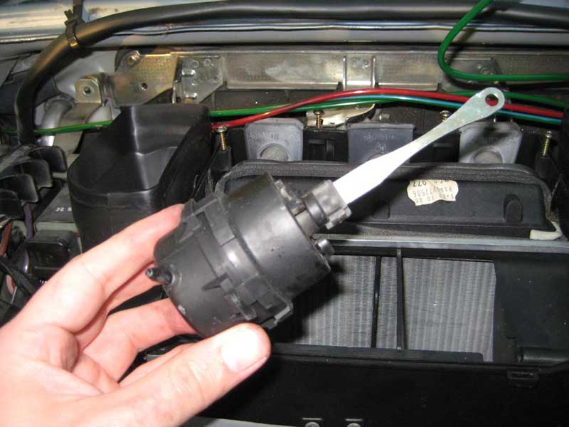
3) Where is the center vent pod? It's inside the airbox, of course. Follow the upper red line from the right of this picture -
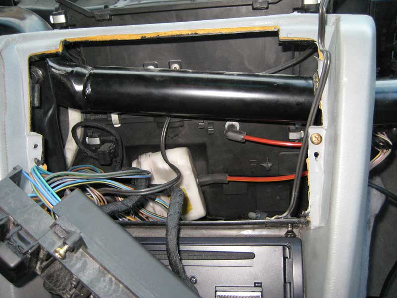
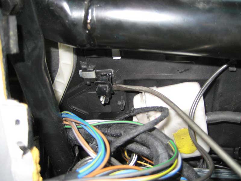
The elbow goes through the airbox wall to another eblow inside the airbox. The 2 rivets you see just above the black pipe going across the dash area hold a bracket that holds the center vent pod. Nothing to do in this step beyond getting oriented. Note the electrical connector with the looped pigtail to the upper left of the white plastic box (footwell pod). I had to do some work with that connector. If you find yourself in the same situation, there is a temp sensor at the other end of that connector.
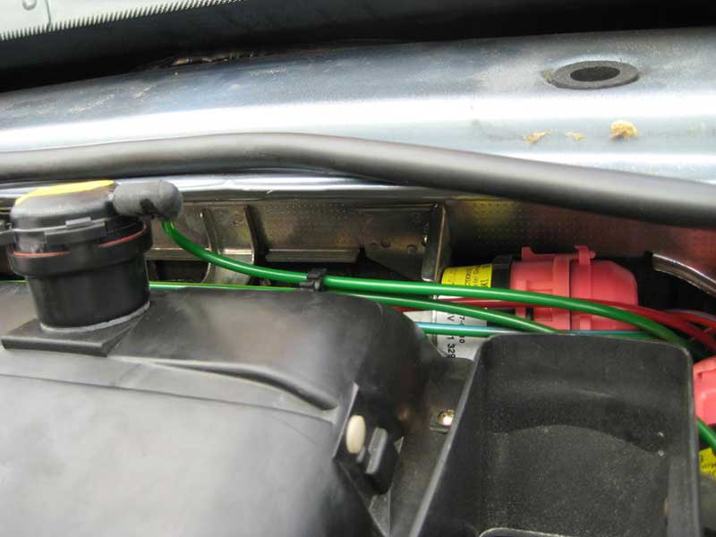
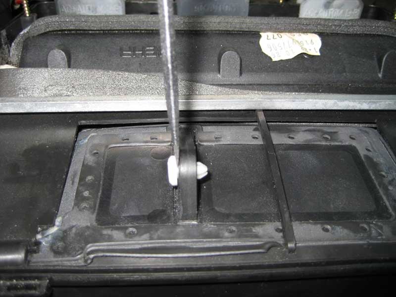
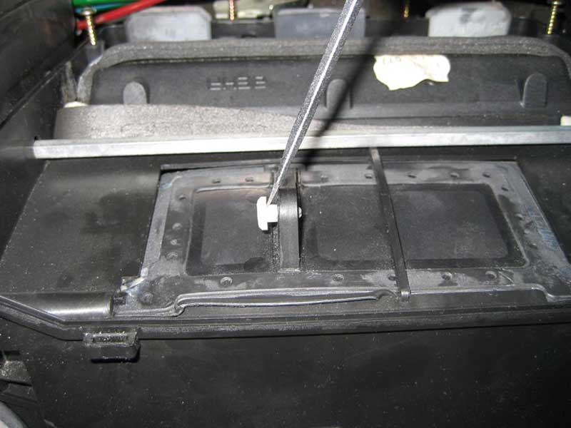
4) Looking at the top of the airbox with the top cover off, you'll see a flap with a series of rubber rivets on the periphery. There is a white plastic pin holding an unseen actuator rod to the flap -

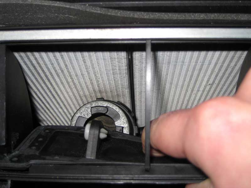
Push down on the flap to see the heater core and the center vent pod -
Fooled you, this is another orientation step
 Now to work...
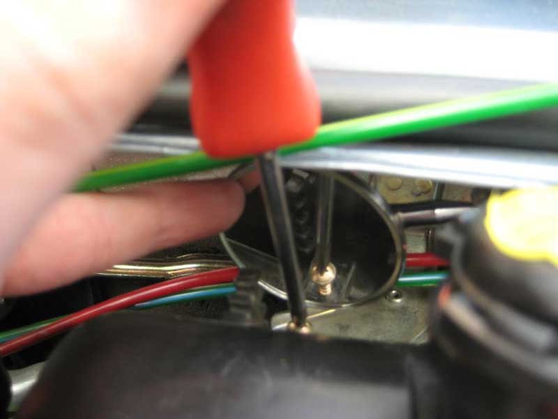
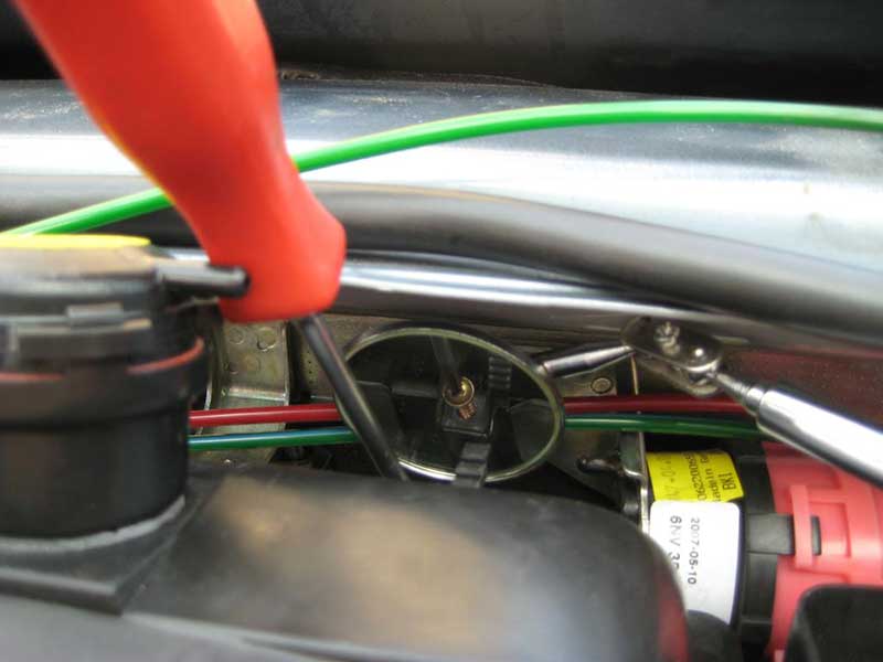
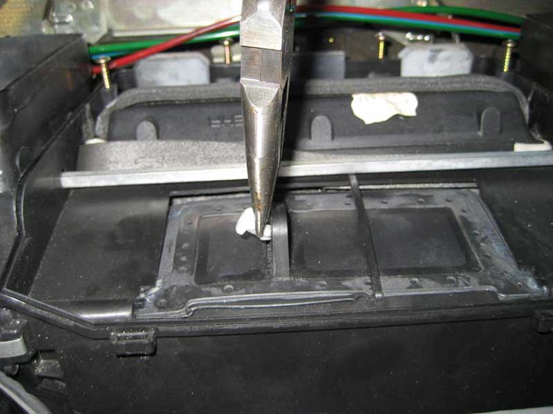
5) I used a small screwdriver to pry out and remove the pin as shown in this sequence -
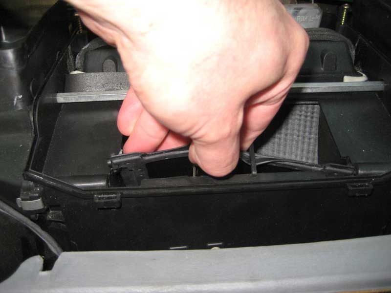
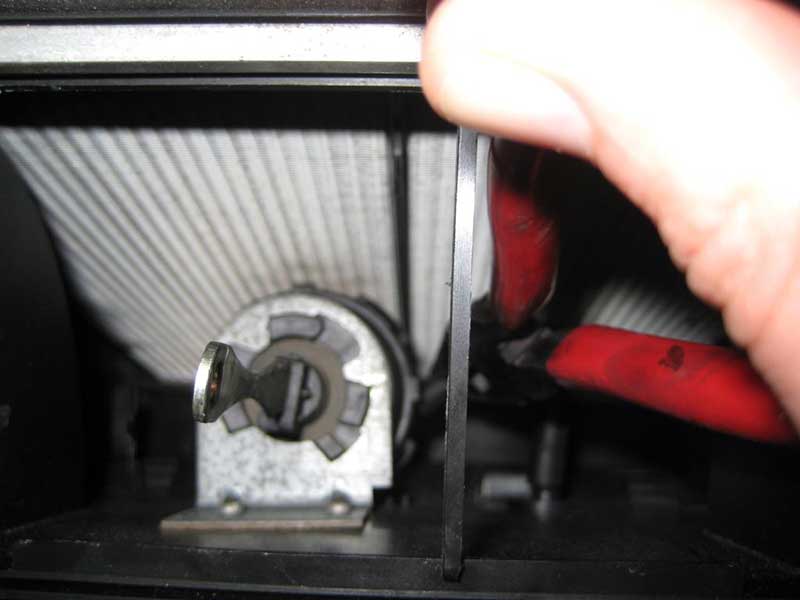
6) I used my hand to pry out and remove the center vent flap as shown in this sequence -
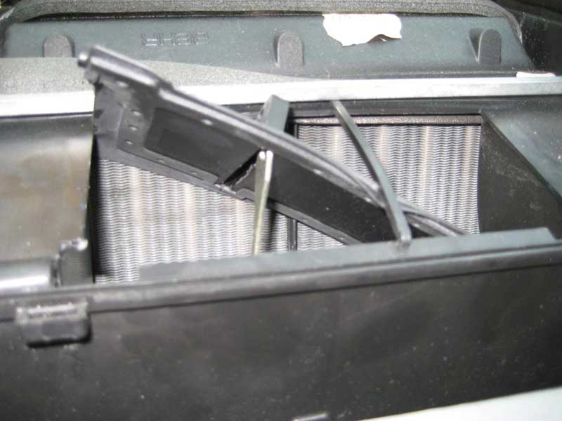

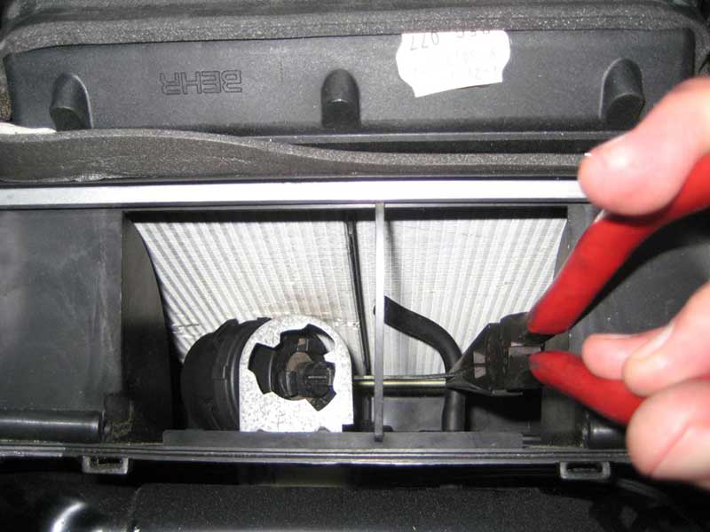
7) I used longnose pliers to remove the vacuum hose from the pod. Fortunately it didn't require twisting like the recirc and defrost pods did. Here's the sequence -
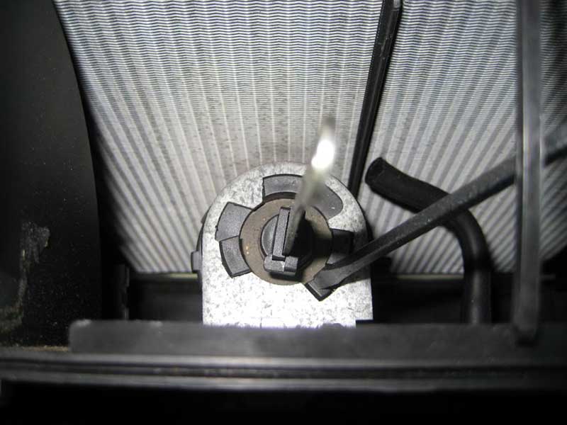
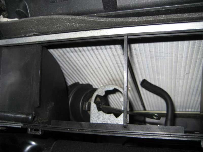
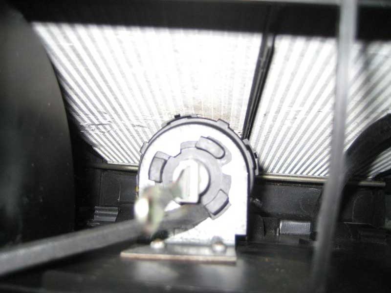
8) The pod is bayonet clipped to the bracket. A CW turn aligns the pod clips with slots in the bracket. Note an extra locking tab at the 5 o'clock position -

Push down the locking tab then turn the pod clockwise so the tabs align with the slots. I used two screwdrivers simultaneously (but I couldn't hold 2 screwdrivers and a camera hence separate pictures); one to push down the locking tab, one to push on another tab to rotate the pod -
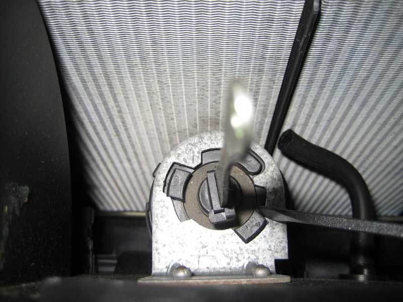
The pod should drop from the bracket on its own or with a little push.
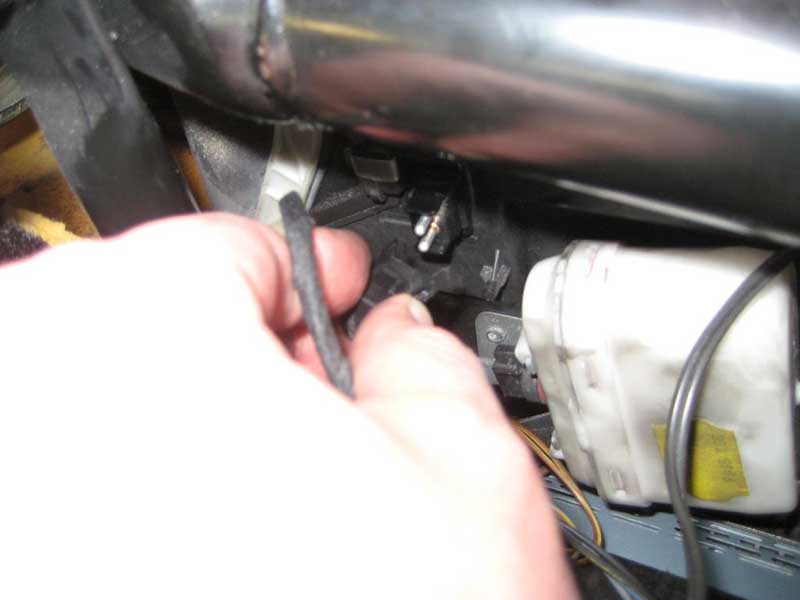
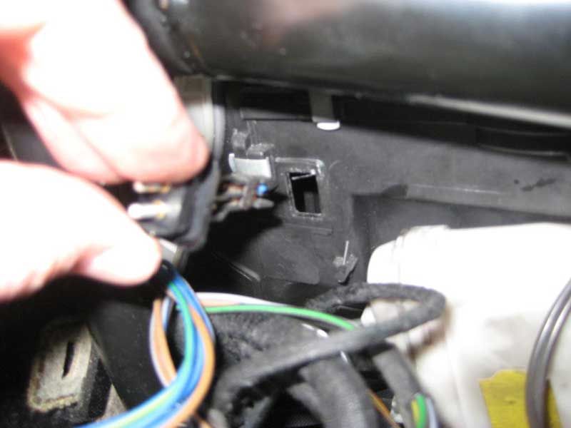
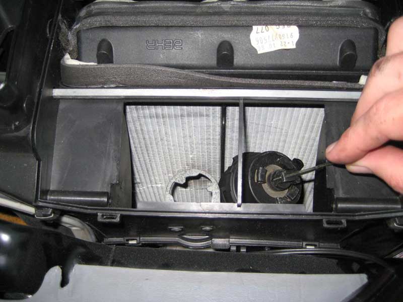
9) I found it easier to maneuver the pod with the temp sensor described in step 3 out of the way. Removing the temp sensor is shown in this sequence. Key to removal was my custom Stanley flathead screwdriver prybar. I forget how I came to bend this screwdriver but it is an indispensible member of my toolbox as is -
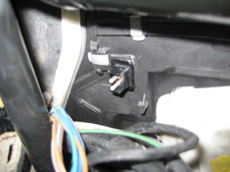
I don't remember how I noted the original orientation of the temp sensor but I know I put it back the way it was originally installed.
10) Words can't adequately describe how to remove the pod from the airbox and I'm sure there are lots of ways to do it. Here's what worked for me. I sent the pod into the cavity towards the driver side where the temp sensor used to be. I had to push the actuator rod into the pod at some point to clear the bracket -

Then I drew the pod to the passenger side -
Then I got the pod over the bracket -
Then I got the pod right under the driver side of the flap opening -
Then I pushed in the actuator rod again to extract the pod from the airbox vacuum chamber first. Voila -
11) I'll pull another Haynes on you and say replacement is the opposite of removal. Do backwards whatever you did to remove the old pod to get the new pod in place. Keep track of the nipple so it's clocked properly when the pod is set in the bracket, but more importantly so you don't push or pull on the nipple or get it caught while wrestling the new pod into place. There shouldn't be too much wrestling.
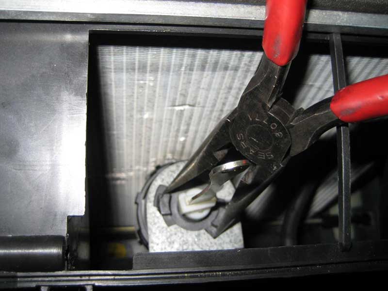
It was easy to push on the locking tab then turn the pod CW to get it off the bracket. It's quite another matter to align the tabs for installation and turn it CCW against the locking tab pushing against the bracket. The actuator rod is free to rotate so you can't use is to clock the pod. I used longnose pliers on the pod clips to get them just started on the bracket then used a screwdriver to engage the clips enough that the pod would stay in place. Mind you don't damage the new pod's diaphragm! -
Then I used longnose pliers like snapring pliers to rotate the clips into full engagement confirmed by the locking tab popping into place -
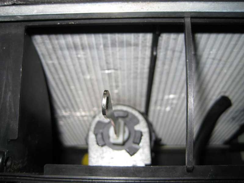
I didn't recognize any clocking to the actuator rod other than the obvious left-right orientation of the pin hole. Why is it always orientation but never occidentation?
12) The center vent flap went back on by hand with the help of a screwdriver on the right hinge as shown in this sequence -

Before engaging the left hinge, engage the actuator rod end into the clevis slot in the center vent flap -
Then fit the pin -

It took some bending to get the left pin into the hinge hole -
Make sure the loose rubber skirt around the center vent flap is seated neatly around the airbox opening. Actuating the flap by hand a couple of times should seat the flap.
Almost there!
13) The last step in this job is to reinstall the temp sensor. I didn't mention in step 9 how I noted the orientation of the temp sensor. I don't know that it matters but I put it back in the same way it was originally installed.
14) I should have said, test the new pod with a MityVac before installation! Then test it again with a MityVac once installed.
Aside from a writeup for removing and installing the dash, I have writeups for the recirc, defrost and diverter pods. I'll add the links as I submit the writeups. The defrost pod can be replaced through the glovebox cavity with the dash in place so the writeup covers that perspective.
The footwell pod is in plain view with the ACC PBU removed and the one in my car is good so I'll save the money and not touch it. I'd do a writeup for the heck of it but I can't figure out how to remove it
Discuss this DIY here.
-sixto
CategoryDiy