Since buying our first Mercedes a year ago - 87 300TD - I've gotten used to the automatic climate control system… for the most part. I had originally started
a thread over here about changing nearly every aspect of the ACC, but I think the only two things I want to modify at this point is control over the center and footwell vents, and maybe someday getting control over the blower speed. The primary reason for wanting control over the vents is that in heating mode, by design, the center vents do not operate. When my hands are cold, I can warm one up with the side dash vent, but not the other hand. Turning on the center vent solves this problem. Also, sometimes the heat on my feet is too much.
Here's a write-up on how I tackled the first project - install a switch to manually choose between the center vent, the footwell vents, or both.
First, a little background information wouldn't hurt…
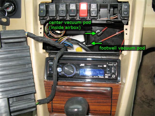
There are three ways in which air enters the cabin: defroster vents, dash vents, and footwell vents. Behind each vent is a flap that is controlled by a vacuum pod. The defroster vent flap and the side dash vent flaps are opened by a shared vacuum pod. The center vent flap is opened by its own vacuum pod, and the footwell vent flaps are opened by one (since 9/86) or two (before 9/86) vacuum pods. Since the side vents operate in unison with the defroster, we'll leave them and focus our attention on only the center and footwell vents.
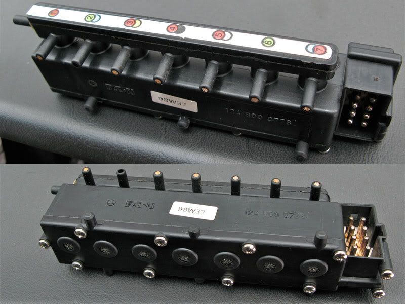
Every flap in the car either opens or closes when its respective vacuum pod gets vacuum suction applied via a vacuum hose. Both the center and footwell flaps are normally closed when their vacuum pod doesn't have a vacuum. When the Automatic Climate Control (ACC) unit wants to open one of these flaps, it switches on one of the solenoids in the switchover valve block (Y7) to direct vacuum to a specific vacuum pod. When the ACC unit wants to close one of those flaps, the respective solenoid in Y7 is de-energized and vacuum suction is removed from that vacuum pod. At this point, the valve on Y7 is switched back to an open port on the back of the unit to allow air to flow into the vacuum hose and back into the pod. This is important because without this open port, the vacuum pod would stay "activated", and it wouldn't be able to return to it's normal position (closed in the case of the center and footwell pods).
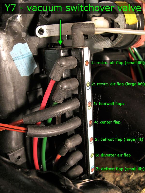
Y7 has a valve on the top where vacuum is always present (sucking, if you will). There are 7 valves on its side that go to 5 different pods. (Two of the pods, the defroster and fresh air pods, each get two hoses going to them to allow for each pod to have two activated states. Applying vacuum to the first valve on the pod makes it partially open a flap, apply vacuum to the second valve on the pod and it will fully open that flap.) Each of the valves on the side of Y7 have a restrictive plug in them to slow down the flow of air. This creates a delay in the opening and closing of each pod which makes the process of opening and closing flaps more gradual, less loud, and probably extends the life of the vacuum pods. Each valve has a different amount of restriction, and on my unit valve number 2 had no restrictive plug (not sure if it use to or not). The back of Y7 contains all the open ports for each valve. When the solenoid for a valve is de-energized, that valve is open to one of these ports for air to flow through to the vacuum pod allowing its internal spring to return it to its normal state.
The ACC unit is programmed to send heat primarily through the defrost vents and the footwell vents, keeping the center vents closed. It is programmed to send cold air through the defrost vents and the center vent, keeping the footwell vents closed. If we want to have manual control over the opening and closing of the center and footwell flaps, then we need to make sure we set our mod up to work in both the summer and winter. Fortunately it's pretty easy to do.
Since the ACC unit always has one of the two flaps open (with the exception of defrost mode), we can combine the two valves that govern the center and footwell pods to give us one vacuum source that's always on when we're in one of the non-defrost modes, and regardless of whether we're heating or cooling. Then we'll split this new combined vacuum source to two separate switchover valves that will connect to the center vacuum pod and the footwell vacuum pod. (I'll call these new switchover valves
vacuum relays to keep things clear.) We'll wire these vacuum relays to a new switch on the console. In order to use a stock Mercedes switch with three positions, we'll need to have our vacuum relays perform the opposite function than Y7 does. Namely, when the vacuum relays are
not energized, vacuum flows to the pods activating (opening) them. When the vacuum relays are energized, vacuum is blocked, and the pods are connected to an open (non-vacuum) port.
The switch will be a rocker switch with three positions:
- up - center vents only (footwell flaps closed, footwell vacuum relay energized)
- middle - center and footwell (both vacuum relays de-energized)
- down - footwell vents only (center flap closed, center vacuum relays energized)
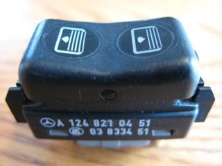
We need a switch that will stay in each of the three positions. The way to connect the hoses to our vacuum relays and the way to wire them to the switch will depend entirely on what switch you will use. I looked for a switch with pictures that could depict upper and lower vents, and found one close enough, but it wasn't the right type. It was a rear window screen switch (124-821-04-51), but the rocker didn't stay in the up or down position, and the caps are too integrated with the inside mechanisms to move it to another switch.

If anyone can figure out how to modify this switch, that'd be awesome! Other switch suggestions are welcome too.
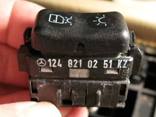
There are probably more options than I found at a junk yard covered in several feet of snow (I couldn't get into half the cars), but I settled on the interior dome lamp switch (124-821-02-51).
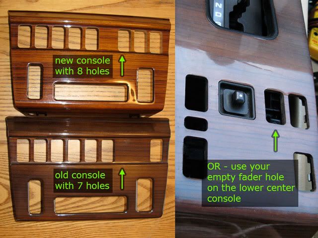
In order to make room for this switch, I found a console panel that matches my interior, but with one extra switch opening. If you have installed a new stereo that doesn't use the factory fader, you could use the space where the fader switch is - I'll cover both options.
 You will need:
- two vacuum relays (vacuum switchover valves) 0015407097, $20 each or less from junk yard - many models have at least two of them
- wiring harness for the vacuum relays, or four butt connectors that'll fit over the pins
- 5' of vacuum hose - I used .170" ID polyethylene tubing which fits really well over the valves on the vacuum relays
- two 3/16" hose couplers
- two 3/16" hose three-way couplers, wyes are better than tees, or you could use one four-way coupler
- two check valves (pet stores have nice small ones)
- an ON-OFF-ON SPST rocker switch for the dash, with wiring harness - I used an interior dome lamp switch (124-821-02-51), but others will do
- any extra junk switch and harness for an extra pin and socket to properly rewire the above switch to illuminate with the other switches at night - find one where the pin is easy to remove (124-820-34-01 works great)
- several feet of wire, preferably a few different colors
- electrical connectors (I used what I had, you may want to do things differently, so I won't list every single one)
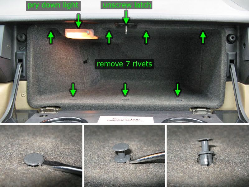
1) Remove the glove box liner. There are 7 plastic rivets along the inside of the glove box (4 on top, 3 on bottom). Pry up the rivet with a flathead screwdriver about a half inch. You will then be able to remove the two-piece rivet. Unscrew the latch at the top.
2) Pry down the front of the light cover and pull it out to disconnect the clip. Pull down on the top center of the glove box liner about 1/2" then pull out.
 3)
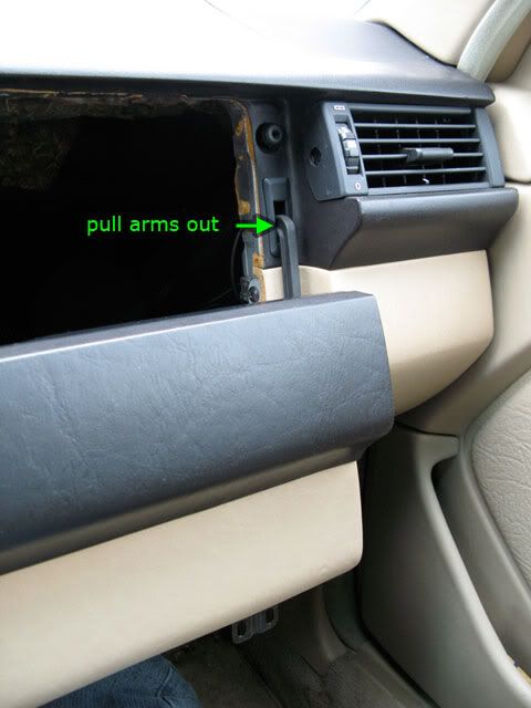
3) Next unscrew the glove box door hinges. You can then remove the arms from the dash by letting the door hang down (in its upright position, like when it's closed, only dangling down below the opening), then pull the arms out of the rubber opening. You can alternatively pry out the rubber grommets to make more room for getting the arms out.
 4)
4) Locate the vacuum switchover valve (Y7) at the left of the glove box opening, on the right (passenger) side of the air box.
 5)
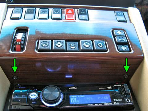
5) Remove the center console panel by unscrewing the two screws directly above the stereo. Gently pull outward from the bottom of the panel and it will hinge at the top until you can pull the panel off.
 6)
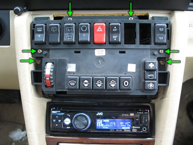
6) Unscrew the ACC unit. There are two large screws and four smaller ones. Pull the ACC unit out and leave it hanging to the driver's side. You can keep it plugged in.
 7)
7) If you are using the fader switch hole for your new switch, then you'll need to remove the lower center console.
Continued...