Now we're on to the switch.
This next section will depend greatly on the type of switch you are going to use.
If you're not using the same type of switch that I am, then you're on your own.
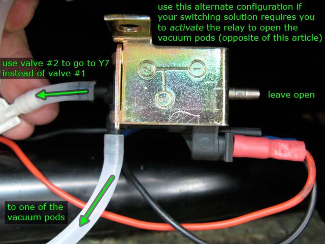
The only thing you need to know is that with the way the vacuum relays are configured with the hoses, powering the relay will stop the vacuum flow to the pod, closing the flap.
If your switching solution requires that you do the opposite (energize the vacuum relay in order to send vacuum to the pod, opening the flap), then you just need to move the hoses from the bottom (valve #1) of the vacuum relays to the top (valve #2).
Leave the hoses connected to the right angle valves (#3).
This document, page 8, helps describe the vacuum relays (they're called vacuum switchover valves).
You can install the switch as is, but the way we're using it, the illumination LEDs do not work when the switch in is the "up" position.
So we need to install a new ground pin to separate the illumination circuit from the switch circuit.
Steps #19-26 are optional, but I recommend them.
If you want to skip them, then I would not recommend connecting an illumination wire to this particular switch.
(OPTIONAL - but recommended)
19) Pry off the cover of the junk wiring harness.
You should be able to easily remove any one of the sockets, keeping the wire attached.
 20)
20) Pry off the cover and base of the junk switch you have.
You need to remove one of the pins. Find one that can easily be disconnected from the inner wiring, unsolder where necessary.
Usually the pin connected to a resistor or an LED is easiest.
Others may be pressed into metal plates or washers.
In either case, the pin is press fitted into the plastic and can be very hard to pull out.
I found that pressing the hot soldering iron against the exposed portion of the pin will heat it up enough to melt the plastic around it just enough to ease its removal.
You could also cut the plastic around it.
Once the pin is out, set it aside with the socket from the last step.
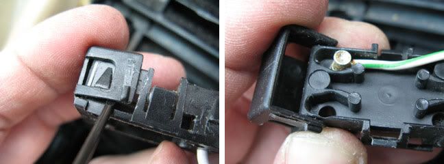
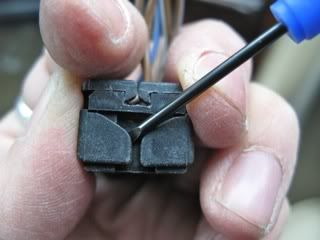
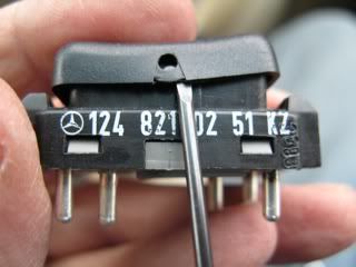
Here's the switch I used for the pin:
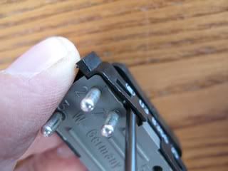
Pry off the bottom:
This is an easy pin to remove.
Just unsolder the resistor and heat the pin to melt the plastic surrounding it.
Slide it out.
 21)
21) Now pry of the one side of the cover of the wiring harness you got with your new switch.
You'll need to pry off the side with the numbers 1, 3, and 4.
Add the socket you removed in the step #19 to spot #4.
Close the clip.
 22)
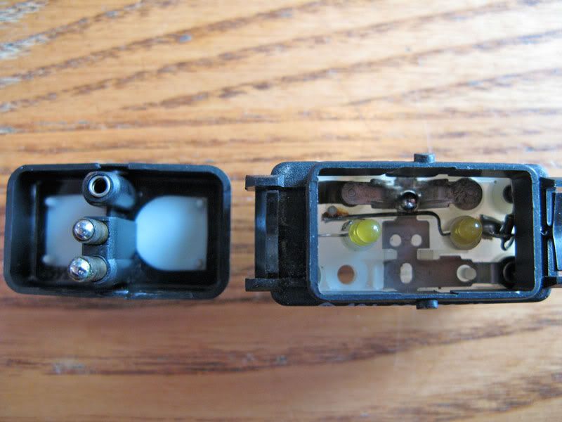
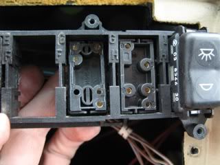
22) Take the new switch and remove the top cover, keeping in mind how it goes back on.
Look inside and take a picture or note how it all fits together.
Remove the ball bearing and any loose springs, set them with the top.
(I didn't have any photos of the switch before I altered it, so I used a newer version of the switch with the same insides for these next three photos.)
Watch out for these ball bearings, shafts, and springs.
They will fall out.
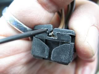
 23)
23) Flip the switch over and remove the bottom (gray plastic) by prying with a very small screwdriver to lift the plastic case free from the four little tabs.
Be careful not to break the plastic.
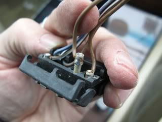
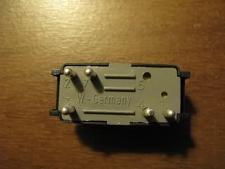
 24)
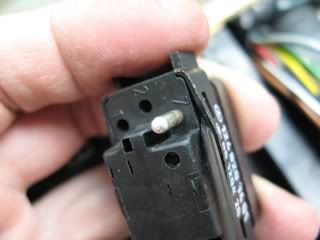
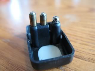
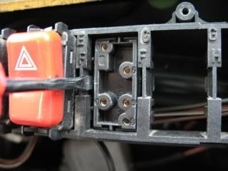
24) Find the hole labeled #4 in the bottom of the switch.
Take the pin you removed in step #20 and press it firmly into that empty hole from the top.
Be sure it's in there very tight.
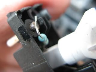
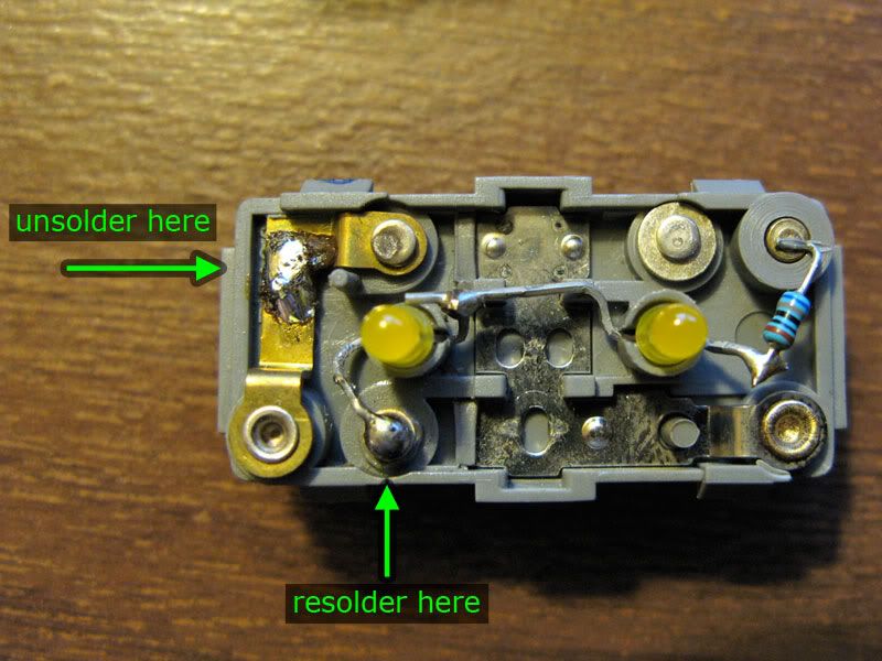
25) Notice how one lead of the LEDs is soldered to the metal strip connecting pin 1 to 5.
Carefully unsolder this lead. Use some small needle-nose pliers to bend the lead over to your new pin in hole #4.
Solder it to that pin.
 26)
26) Put the switch back together.
Make sure it fits into your wiring harness.
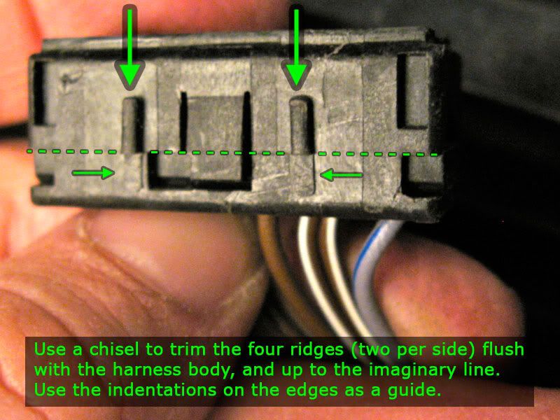
27) If you are installing the switch into the lower console in place of the fader switch, you will probably need to shave off a small amount of plastic from the four little ridges on the sides in order for the switch to rest low enough in the empty space left by the fader switch.
 28)
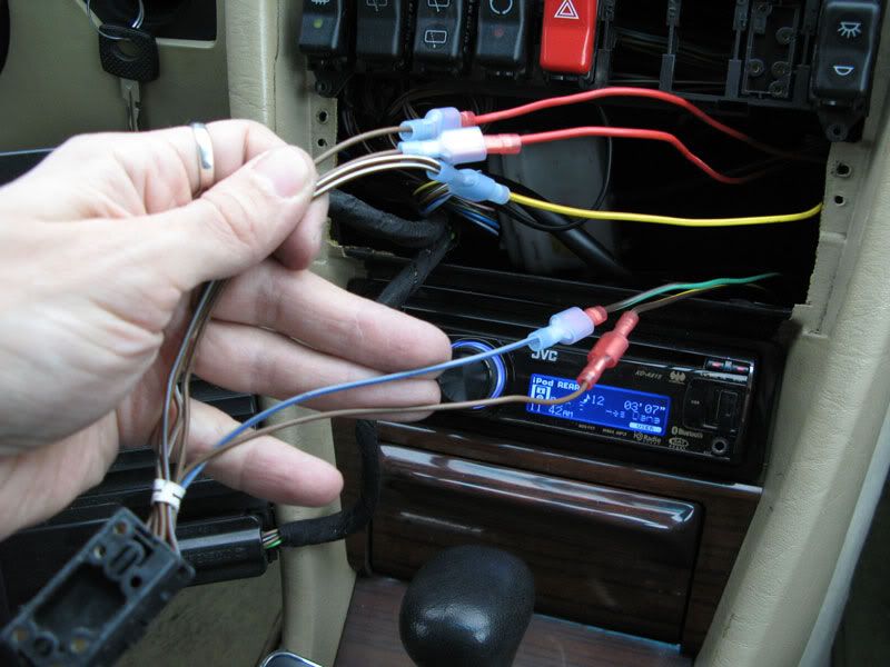
28) Feed the wires of your wiring harness through the appropriate opening above the ACC unit (or in the fader spot).
Connect the wire like this:
- pin 2 (gray/blue): power for the illumination - find one to tap into, usually a gray/blue wire, I used one from my old fader switch
- pin 4 (what ever color you got with your socket): ground for illumination - again, I used one from my old fader switch
- pin 3 (two brown/white wires together): hot from the glove box light (or other source that's only on when the key is in the "accy." "run" or "on" position) - this powers our vacuum relays
- pin 1 (brown): connect to the vacuum relay for the footwell pod
- pin 7 (brown/blue): connect to the vacuum relay for the center pod
 29)
29) Test the switch.
- When the switch is in the upper position, it energizes the footwell vacuum relay and no air comes out of the footwell vents.
- When the switch is in the center position, neither of the vacuum relays are energized and air comes out of both center and footwell vents.
- When the switch is in the lower position, it energizes the center vacuum relay and no air comes out of the center dash vents.
If the upper and lower switch positions do the opposite of what is described above, just swap the wires to pins 1 and 7.
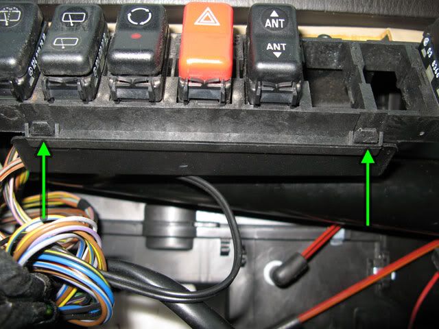
30a) Remove the plastic thing covering all the wires to the switch harnesses behind the switches.
Press in the four tabs (two above and two below the switches).
It's a tight fit behind there, but it's flexible so just work it out to the right and down.
Insert your new switch wiring harness (without your switch plugged into it) in through the back of the empty spot above the ACC unit.
If you need to move or rearrange any switches, the harnesses will come free if you apply a little pressure with a screwdriver on each side of the harness.
 -OR-
30b)
-OR-
30b) If you are putting your switch into the fader switch spot, first rest the switch into the empty spot and make sure it rests level with the passenger window switch.
Cut extra off the plastic ridges (see step #27) if necessary.
Put the switch into the harness and clip it up onto the back of the wooden console panel (just like the fader switch did).
I do not have any picture of this.
31) Tuck all wires out of the way and put the ACC unit back in place.
32) Install your new console panel with the opening for your new switch (or if you used the fader spot, screw the lower console panel back in place).
33) Put the glove box door back on, followed by the glove box liner (don't forget to pull the wires for the light out through the opening in the liner), then the latch at the top of the liner.
34) Enjoy!
-Zeb