|
DIY: M110 Crankshaft Seal R&R
Like all seals in vehicles that are 20 years or older, the engine Front Main Seal is prone to failure. The rotary seal mounts in a housing and surrounds a turning shaft. The lip always faces the fluid it seals in, and the garter spring provides gentle pressure between the lip and the shaft. With age or mileage, or a combination of both, the seal will lose that ability. The seal may harden due to heat, it may lose its original tolerances through wear due to the constant rotation of the shaft, or the seal may loosen from the casing in which it is installed. If signs of leaking oil are present, it is probably time to replace the seal.
To use an old cliché, There is more than one way to skin a cat! Many methods have been used to R&R the Front Main Seal, with varying degrees of success. The MB FSM (Factory Service Manual) shows Special Tools which are utilized for the job. Some of these tools are cost prohibitive for the average weekend wrencher, who will only undertake this repair once. Very understandable! Thus, some ingenuity and creativity may come into play when replacing the Front Main Seal. Less expensive generic tools can be used, and some may be available from the local parts suppliers on a rental basis. I wont get into all the various methods, but will focus on what I have used.
In this article, I will show the Crankshaft Seal R&R utilizing the Special Tools per the FSM, which I am fortunate to have access to. I must say, using these tools, there was little struggle. The Special Tools did perform as designed and simplified the whole job. Some preliminary phases of the job (IE Fan removal, Radiator removal, Belt Removal, etc.) are not described here, as they have been covered in other articles, and are Engine 110/ Chassis-model specific. The MB parts numbers listed are for my particular application, Chassis W123.053, and Engine M110.984. They may or may not be applicable to your particular Chassis/Engine.
Its difficult to put a time on this job. I worked slowly. In addition to the Front Main Seal, I chose to install a new Spacer Ring (which the Seal rides on), a Water Pump, the illusive Water Pump Hose, Hardware, Belts, and a few more odds & ends. The car is a Concours car, so cleaning up and detailing the front of the engine was in the plan. The Fan, Counterweight, and Vibration Absorber were cleaned and painted. Much time was spent beyond the basic Seal repair. Without the Special Tools, the job would have taken me much longer, without a doubt. OK, time to get dirty. Lets begin.
VEHICLE: Mercedes-Benz 1978 280CE. Chassis - W123.053. Engine Class - M110.984
SYMPTOMS: Oil leak emanating from Crankshaft Front Seal and signs of oil behind Crankshaft Counterweight and front of Oil Pan.
OBJECTIVE: Remove and Replace Front Main Crankshaft Seal. Remove and Replace other Optional Components.
PARTS:
* Seal & Associated Parts
Seal Ring (0039970347)
Spacer Ring (1100310051)
Dowel Pin X 2 (000007008244)
Disc Spring X 4 (1279930026)
Screw (308676018001)
Screw X 6 (000912008210)
Washer X 6 (000433008406)
* Optional Water Pump & Associated Parts
Water Pump (1102001720)
Water Pump Gasket (6162010080)
Screw X 5 (914141006300)
Breather Line (1102000258)
Hollow Screw X 2 (915036005100)
Seal Ring X 2 (007603-008100)
* Optional Hose
Hose Thermostat Housing to Water Pump 45 mm (900271042012)
Hose Clamp X 2 (0069972690)
Gasket Thermostat Housing (1102030280)
Screw X 3 (000912008067)
Spring Washer X 3 (000137008204)
* Optional Drive Belts
Belt Alternator/ Water Pump - 9.5 X 960 (006 997 18 92)
Belt Refrigerant Compressor - 12.5 X 1285 (005 997 98 92)
Belt Power Steering - 12.5 X 825 (0069973692)
Belt Air Pump - 9.5 X 825 (0029975792)
SUPPLIES: Permatex High Temp Sleeve Retainer #64000, Permatex Water Pump & Thermostat Housing Gasket Maker #22071, Victor Reinz Reinzosil (Equiv MB 003 989 98 2010). Wet-or-Dry 320, 400, & 600, Lacquer Thinner, Mineral Spirits, Isopropyl Alcohol, Acme Finish #1 FT220 Wash Solvent, Q-Tips, Shop Rags, Paper Towels. Aerosol Rust Converter, Aerosol Flat Silver Paint, Aerosol Satin Black Paint, & LUCAS RedNTacky #2. Anti-Freeze 1.75 Gallon, ATF Dexron/Mercon 16 Ounces. (*** No endorsement of any products used is being made or implied***)
SPECIAL TOOLS:
Puller/ Installer MB 116 589 10 33 00
Flywheel Lock - MB 110589004000
Extractor - Sir Tools M0033
Mounting Tool MB 110 589 07 61
Torque Wrench ¾ Drive 100-600 Ft. Lbs. - CDI 6004MFRMH
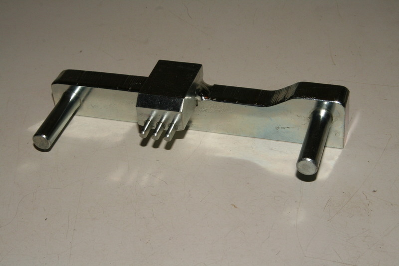
Crankshaft Counterweight Centering/Adjusting Tool Shop Fabricated
Prior to Commencing, I highly suggest: Taking pictures as you go along, and, Dont throw away any parts till the entire job is complete!
First, Drain Radiator of Coolant. Some people have performed the Crank Seal R&R with the Radiator in the vehicle. Since I was replacing several cooling system components, the coolant needed to be drained. Also, the Puller/Installer tool required clearance. Remove Hoses from Thermostat Body and Lower Pipe. My Radiator has an inboard oil cooler for the transmission. (Your vehicle may differ.) The Cooler Lines needed to be disconnected. I opted to disconnect the flex lines from the hard lines at their union, rather than at the Radiator. A Flare-nut wrench is highly recommended, so as to not round-off the soft fittings. Hint Use baggies with tie wraps around all open pipes/ hoses/ fittings. This will keep out dirt and keep you dry.
Loosen Fan Shroud. Remove two clips that secure the top of the Fan Shroud to the Radiator. Hint Cut a piece of cardboard the size of the inner radiator surface. Carefully place it inside the Shroud between the Radiator and the Fan blades. Insurance.
Remove Fan and Clutch from Water Pump Pulley. Remove the four 10 mm bolts that connect the Clutch to the Water Pump. These can be a pain. Try not to round-off the heads. Hint - A ground down 10 mm box head wrench will help and save the bolt heads. Move cautiously so the fins of the Fan do not contact the radiator. This is where the cardboard protector comes in handy.
Remove Fan Shroud. Expect a little twisting and turning, as you lift up.
Remove Radiator. Remove two clips which support the Radiator to the radiator support. Carefully lift Radiator upward and out of the two lower Rubber Mounting grommets. Hint Place the piece of cardboard you cut earlier against the A/C Condenser Fins.
Remove Drive Belts. This requires loosening the tightening nuts and adjustment bolts on all the accessories. In my case, these were the Alternator/ Water Pump, the Refrigerant Compressor, the Power Steering, and the Air Pump. These vary from model to model. As I recall, mostly 17 mm and 19 mm sockets and box end wrenches were used.
Remove Drive Pulley and Vibration Absorber. These are secured to the Counterweight with six Allen head bolts. Use a 6 mm long Allen socket. The Allen may twist due to torsion. I used a 6 mm Allen on a 10 mm shaft, which eliminated this twisting effect. Hint - Slightly break each bolt loose, one at a time, then proceed to remove all six. The Pulley should pull off without problem. The Vibration Absorber may require several taps with a rubber mallet. Insure that when it becomes free, it does not drop and damage itself.
Additional Access. This is when I removed the AC Belt Tensioner and later the Thermostat Housing. Since I was working from above (no lift), I wanted good visibility and tool access. Hint Plug the Thermostat Housing opening. If it can fall in, it will!
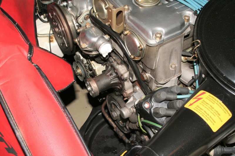 Remove Water Pump Pulley and Water Pump. I planned on installing a new Water Pump, so removal was a logical step. Five bolts hold the Water Pump to its housing. Mine were not rusted. If you have rust, treat them with a product of your choice, and let the penetrant do its job. Unscrew with caution. Hint Once the Water Pump is removed, cover the opening. If it can fall in, it will!
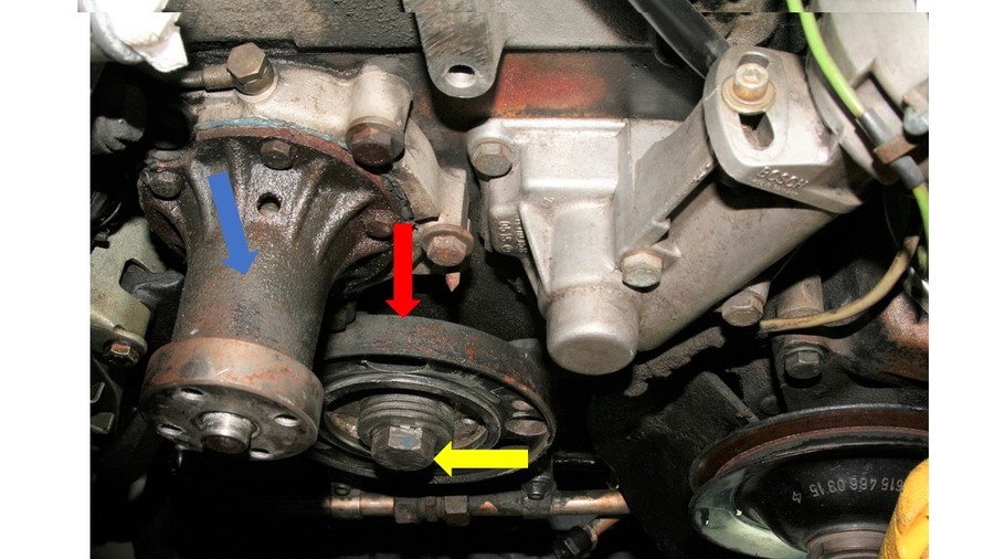
BLUE Arrow = Water Pump. RED Arrow = Counterweight. YELLOW Arrow = Crankshaft Bolt.
Remove Water Pump Pulley and Water Pump. I planned on installing a new Water Pump, so removal was a logical step. Five bolts hold the Water Pump to its housing. Mine were not rusted. If you have rust, treat them with a product of your choice, and let the penetrant do its job. Unscrew with caution. Hint Once the Water Pump is removed, cover the opening. If it can fall in, it will!
BLUE Arrow = Water Pump. RED Arrow = Counterweight. YELLOW Arrow = Crankshaft Bolt.
 Attach Flywheel Lock. To be on the safe side, the engine was set to -0- TDC. I used the Locking device which mounts in the Flywheel Inspection Cover. The Inspection Cover was removed, two lower Bell Housing bolts were removed, and the Flywheel Lock was set in place. The teeth of the lock engage the Flywheel, and inhibit its rotation. A flywheel lock is also available which requires starter motor removal. Other creative methods have been utilized.
 Flywheel Lock - MB 110589004000
R emove Crankshaft Nose Bolt. With the Flywheel Lock securely in place, the bolt can be removed. Since the Bolt on the 110.984 is torqued to 400-450 Nm, I utilized a ¾ drive Torque Wrench and 27 mm deep socket to remove the Bolt. It came out fairly easily with a 40 handle on the Torque Wrench. I suspected that the Seal had been previously replaced and the Bolt not necessarily torqued to spec. Another method to loosen the bolt is to put the socket on a breaker bar, wedged against the frame, and bump the starter.
BLUE Arrow = Water Pump. RED Arrow = Counterweight. YELLOW Arrow = Crankshaft Bolt.

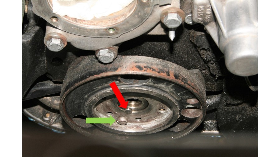
RED Arrow = Dowel Pin. GREEN Arrow = Vibration Absorber guide pin.
 With all components removed, I had much more access to the Counterweight and Crankshaft Nose Bolt. This gave me room to muscle the 40 Torque Wrench handle.
RED Arrow = Thermostat Housing. BLUE Arrow = Hose Connection Water Pump to Thermostat Housing. PURPLE Arrow = Breather Line Connection. GREEN Arrow = A/C Belt Tensioner Mount. YELLOW Arrow = Water Pump Mounting. ORANGE Arrow = Counterweight.
With all components removed, I had much more access to the Counterweight and Crankshaft Nose Bolt. This gave me room to muscle the 40 Torque Wrench handle.
RED Arrow = Thermostat Housing. BLUE Arrow = Hose Connection Water Pump to Thermostat Housing. PURPLE Arrow = Breather Line Connection. GREEN Arrow = A/C Belt Tensioner Mount. YELLOW Arrow = Water Pump Mounting. ORANGE Arrow = Counterweight.

__________________
Gute Fahrt
|