

|
|
|
|
|
|
#1
 03-10-2009, 02:50 AM
|
||||
|
||||
|
87 300D dash installation
I have a writeup on removing the dash but I think I missed a few steps. Review the replacement steps as well to get a better sense of how things come apart. Someone mentioned that a dash with passenger side airbag is considerably different. I can't argue with that. I can't give you advice about that situation either.
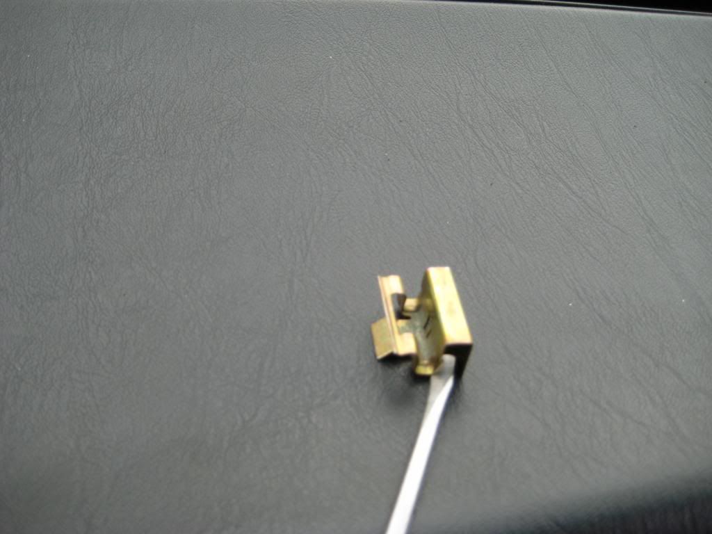
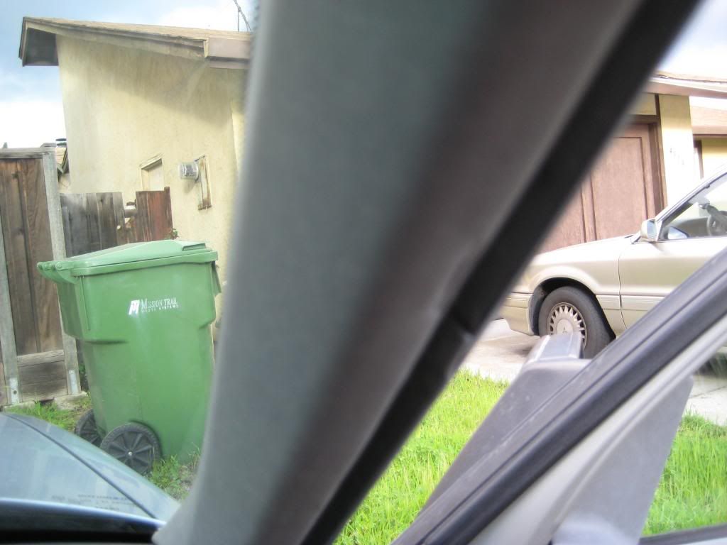
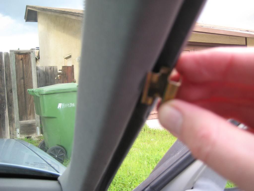
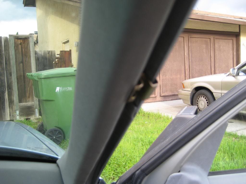
A lot of things are fastened independently of other things so a strict sequence is not possible. I'll describe what I did in sections for my convenience. To put this writeup in context, I replaced the original dash with growing cracks for a later model dash with absolutely no cracks. Jeremy and I wondered if the installation process might stress a dash and thus cause cracks. From what I saw, there's no risk of that. The dash bracing is stiff enough that you can't bend or flex the dash in a way that would induce cracks even if it were sundried... unless you really set out to cause cracks. 1) Set the dash where it goes. I don't have any panoramic views of this but it obviously only goes on one way. Make sure the ears at the forward corners clear the A-pillars. When removing the old dash, I left the steering wheel in place and pulled the passenger corner aft. The ear took a bit of persuading to clear the A-pillar. It wasn't an issue putting the new dash in place. With the dash basically square with the windshield, guide the defroster ducting into place as you push downward on the dash. There's a duct to align on either side of the ACC airbox. Besides the defroster ducts, use the screw holes in the speaker cutouts and the center vent cavity to guide the dash into place. The first picture shows the driver side duct connected. The second picture shows the passenger side duct connected. The junction is right at the top of the picture - 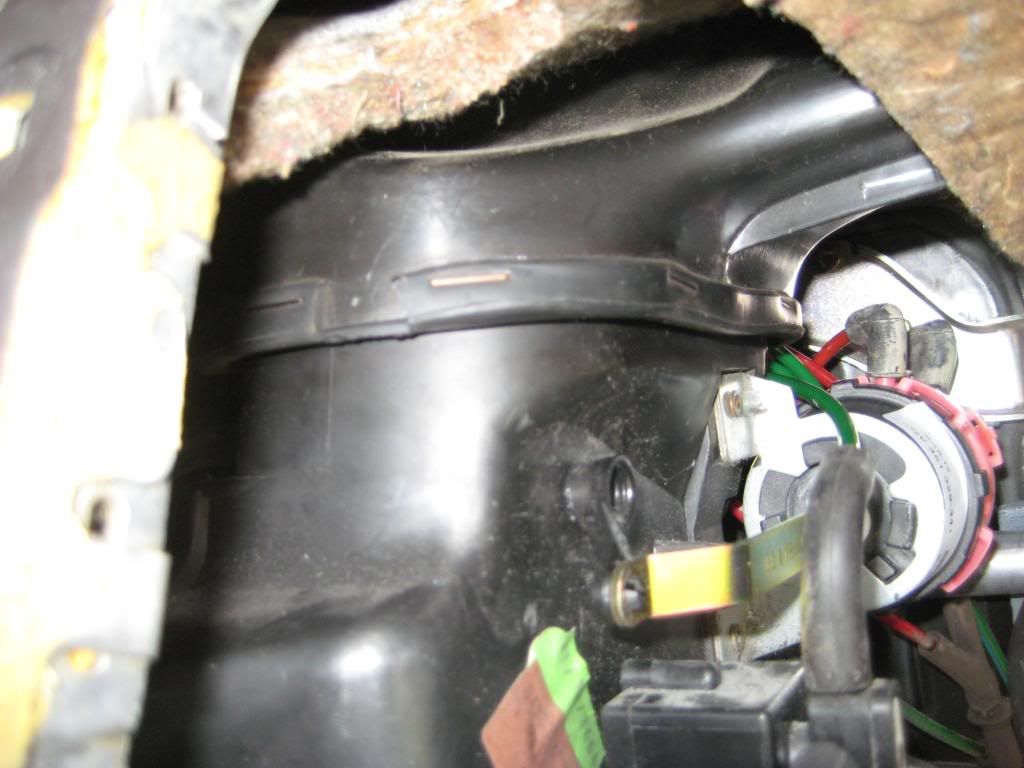 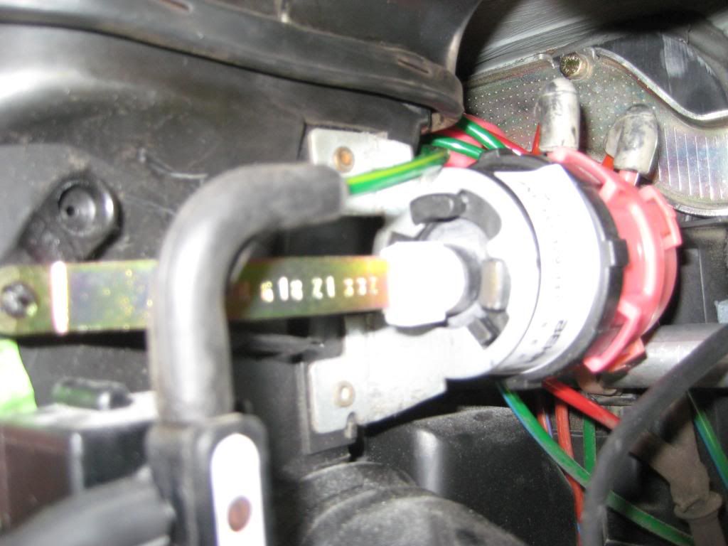 2) This step is tricky. Align the holes at the lower center of the dash with the slots in the upper ledge of the center console. Allow at least a half inch vertical gap between the bottom center of the dash and the top of the center console. Drop the carriage bolts into the dash holes from the center vent cavity. Slide the clips over the bolts. Not a lot of room to do this so you have to be more creative than elegant. The alternative is to put the bolts in place with the dash higher. I tried this but there wasn't enough clearance below the center vent duct to allow the bolts to clear the the console ledge. The first picture shows how I couldn't get the clipped bolts over the console ledge. The second picture shows plan B with a vertical gap. The third picture shows the driver side bolt in place through the slot in the console ledge. The fourth picture shows the passenger side bolt in place - 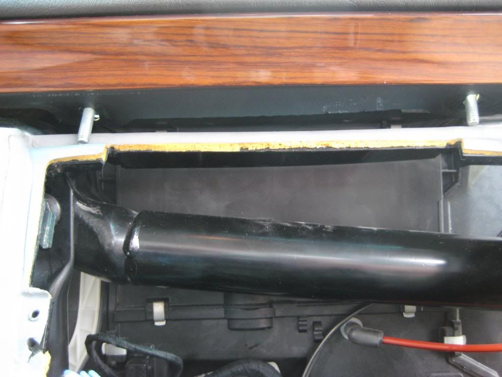 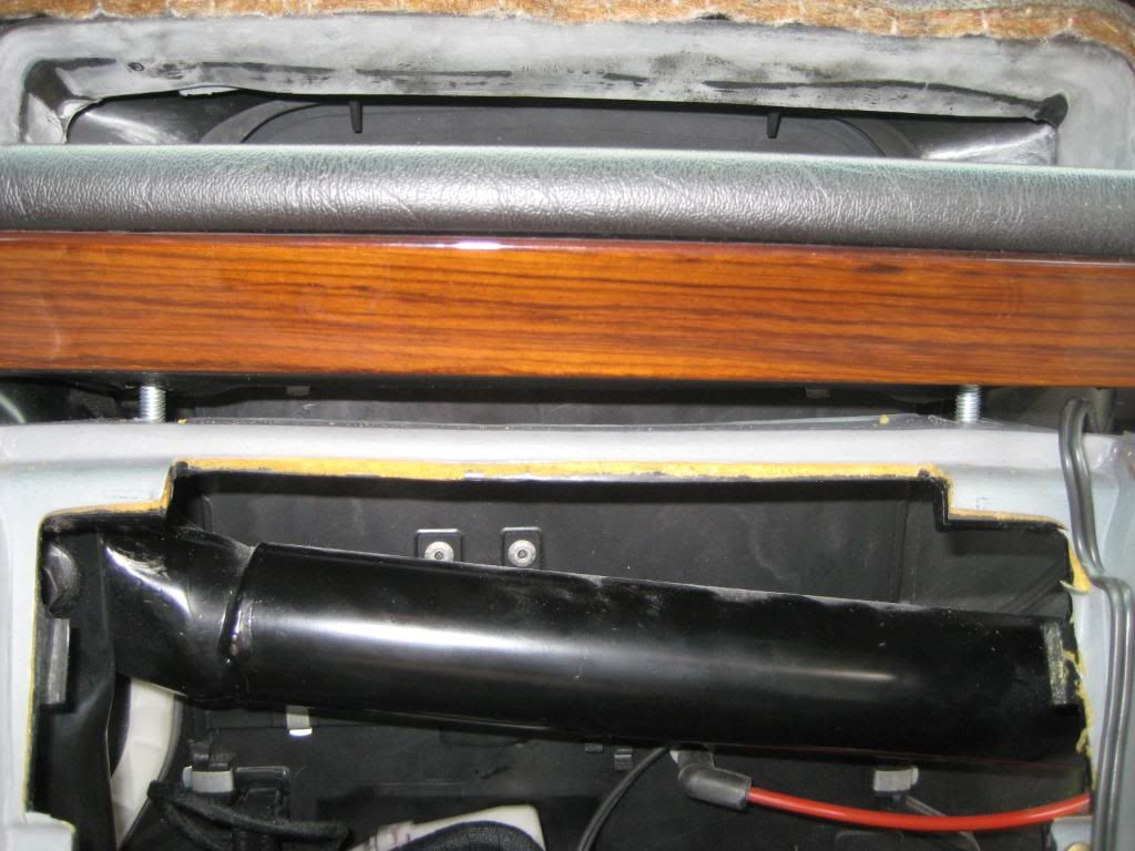 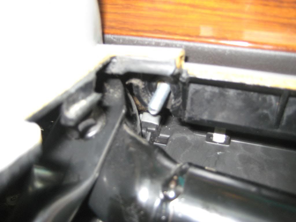 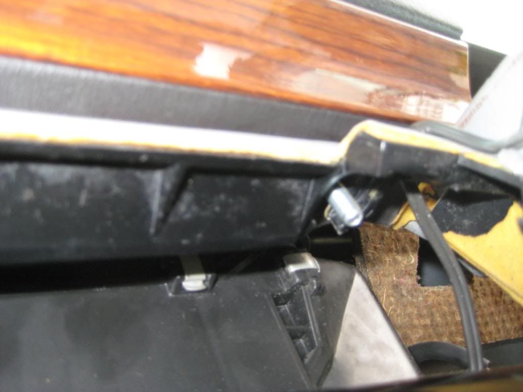 3) Trickiness continues. The first picture shows the passenger side carriage bolt in place. The second picture shows the clip sliding into place. I don't remember if the bottom tangs of the clip go between the dash bracket and upholstery or below the upholstery. Below the upholstery is easier but the clip seemed deformed so I slid the bottom tangs between metal and upholstery. The third picture shows the clip in place. The far end of the clip has a tab that hangs on to the carriage bolt -  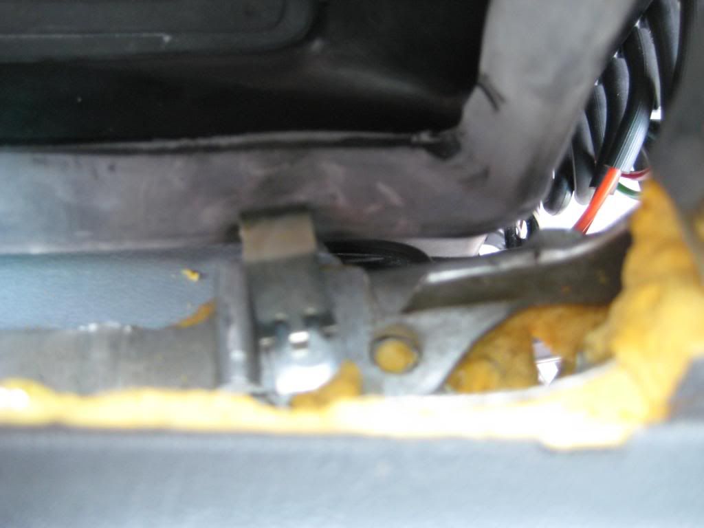 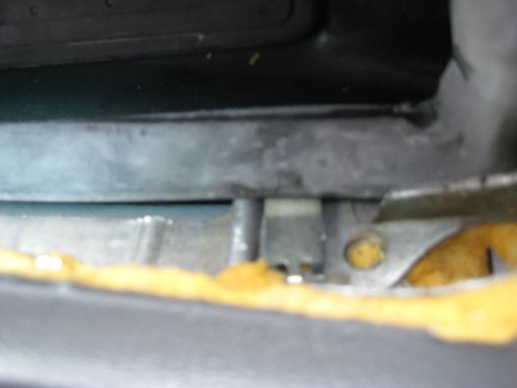 4) The nuts that go with the carriage bolts have captive washers. The nuts take a 10mm wrench. Here are the nuts in place - 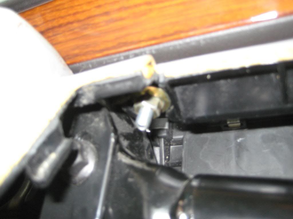 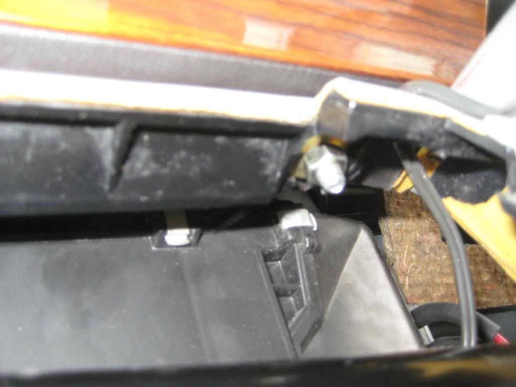 Lots more to do but I found that to be the most difficult part. 5) Put the 2 screws, 1 in each speaker cutout. The screws take an 8mm socket - 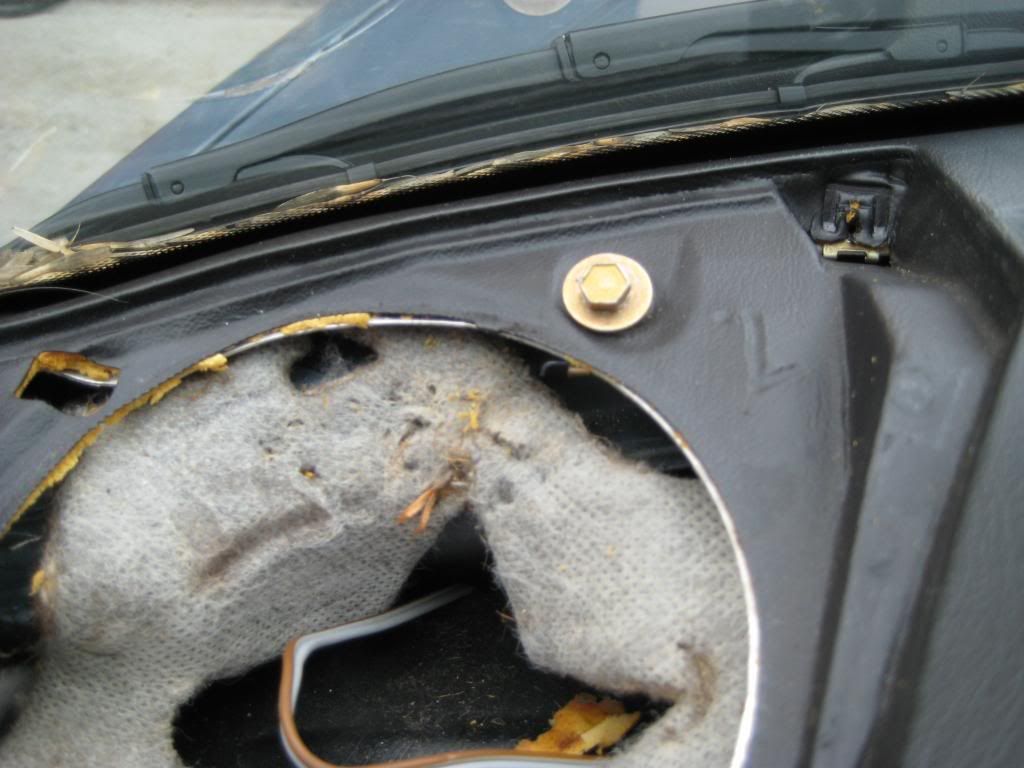 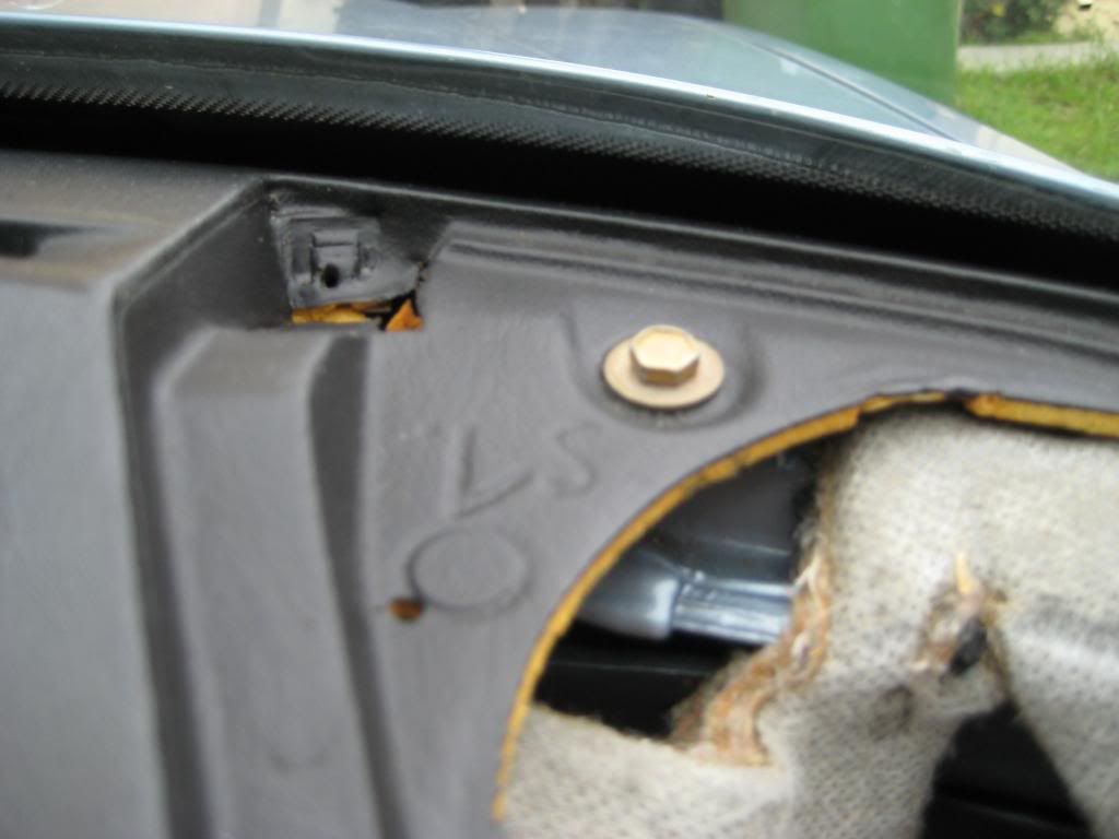 6) The last structural attachment is below the driver A-pillar. You should have a gold colored J-shaped clip. Hook the bracket in the square hole then pivot it so the hook is towards the forward end of the car. Insert the Philips head screw through the dash, bracket and into the nut clip at the far end - 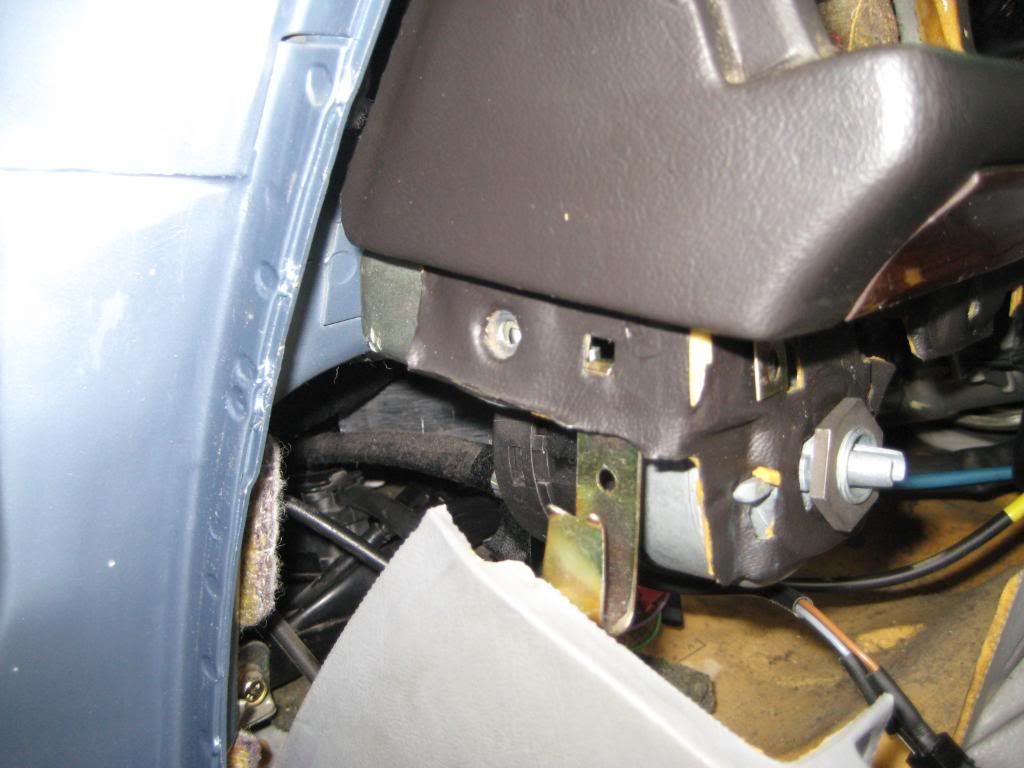 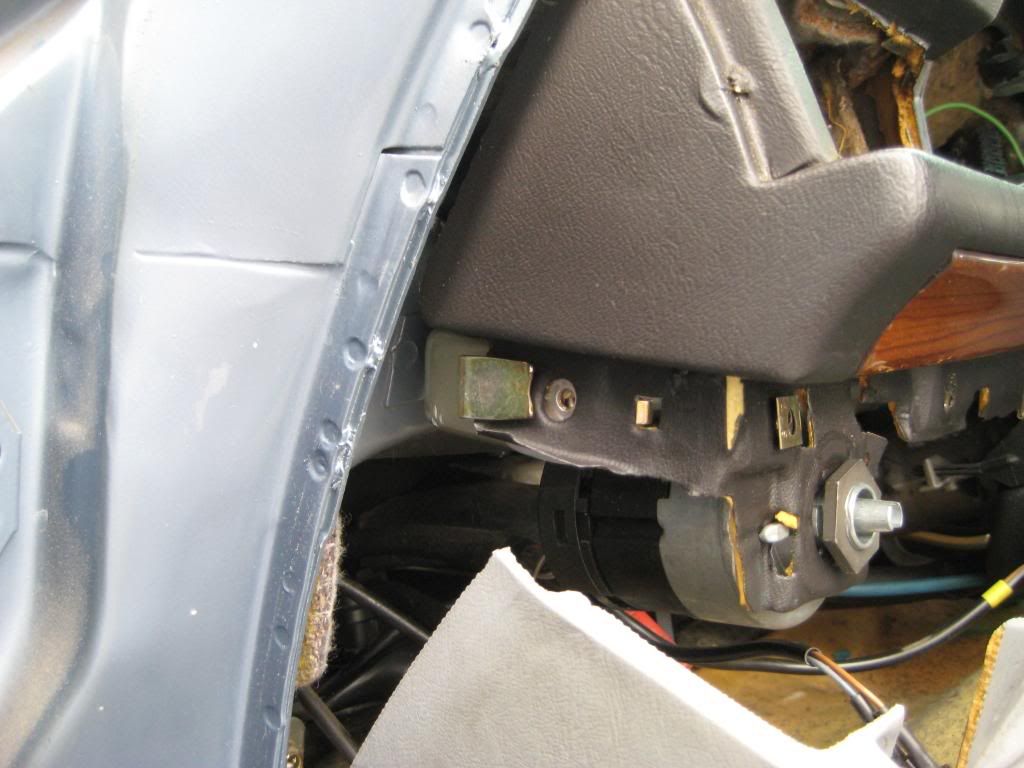 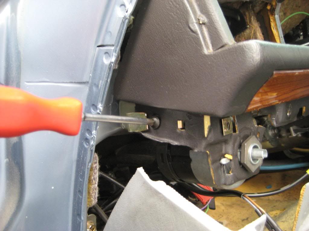 For reference, the bracket between the headlight switch and driver side vent duct is what the screw attaches to. Make sure there's a nut clip on the bracket aligned with the hole. 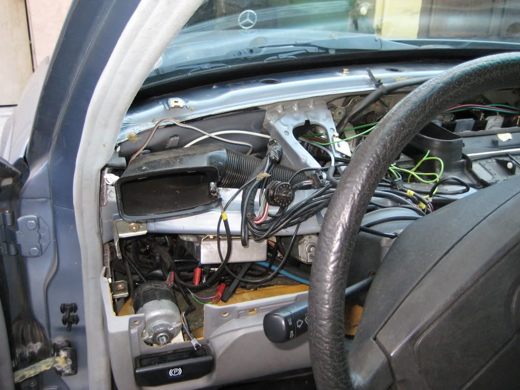 There is no corresponding bracket on the passenger side. The J-shaped clip should still be on the dash. 7) This step isn't structural but if you don't connect the speakers now, you might never get to it. The speakers don't have to come off the dash. I removed the speakers because the new dash had mismatched speakers, one was a factory looking 2-way, so I installed my original matched speakers. You might be strong enough to pry off the the speakers with your fingers. Otherwise gentle prying will lift an edge and you can work your way around to release the speaker. The speaker electrical connectors are unique. Fish out the harness connector then mate the connector ends. The backside of the speaker has 2 spring clips and a tab. I set the tab towards the windshield edge of the cutout then pressed the speaker into its hole - 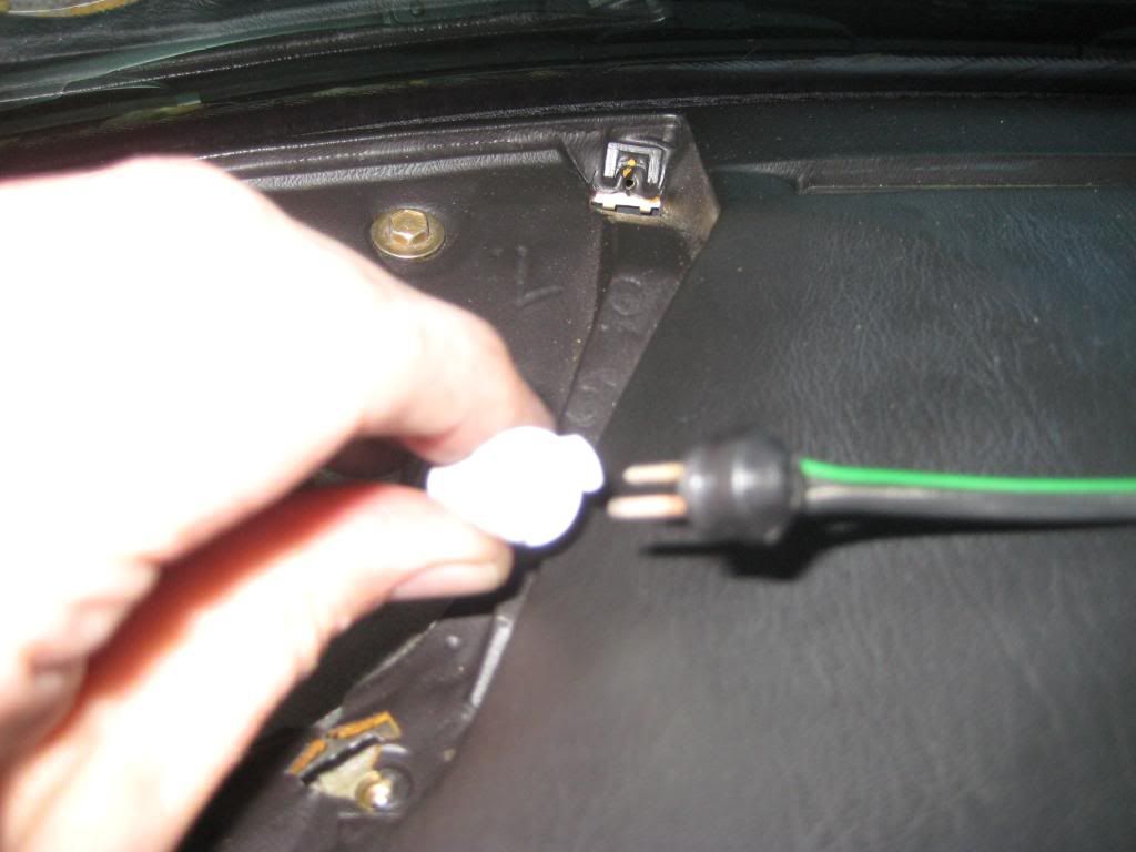 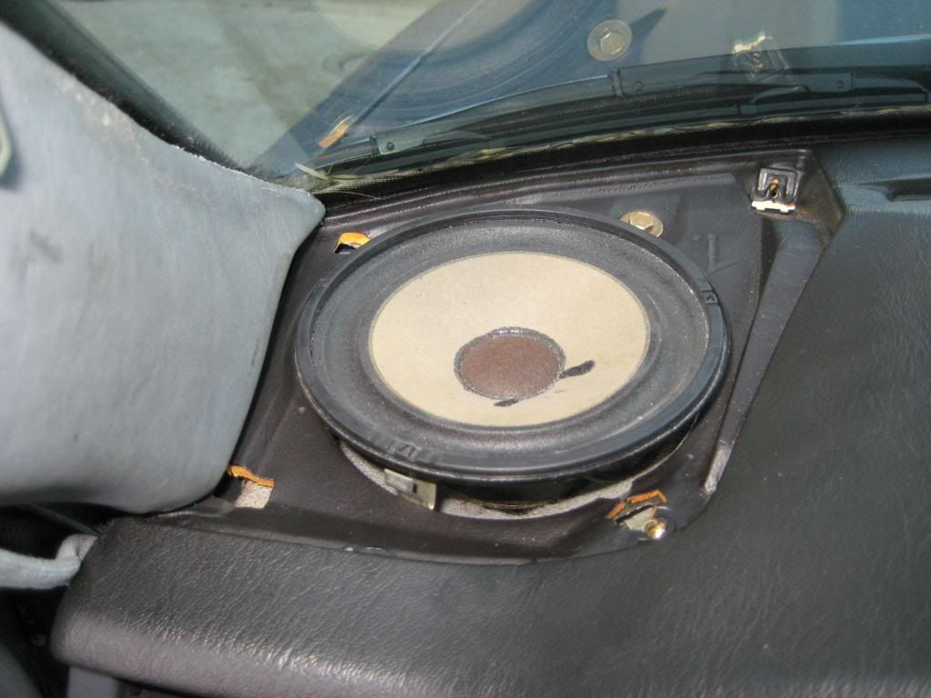 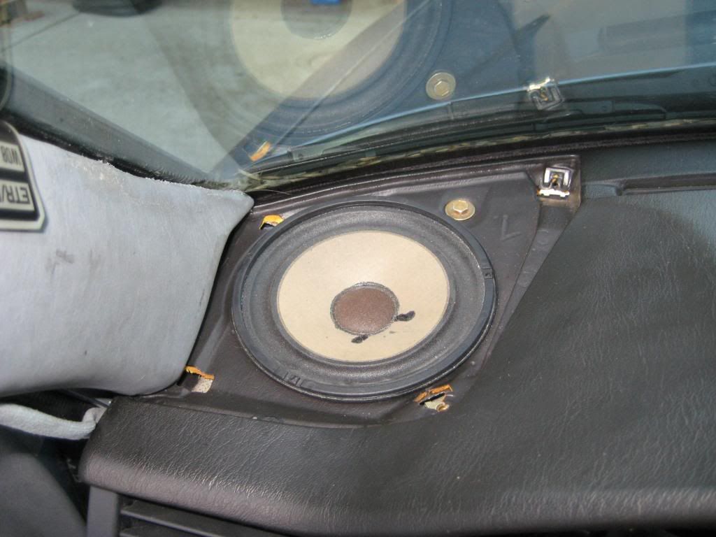 If you don't remove the speakers, fish out both ends of the connectors through the gauge cluster and glove box cavities and mate the connectors. I'll end this chapter here. Sixto 87 300D Last edited by sixto; 03-10-2009 at 03:05 AM. 
|
|
#2
03-10-2009, 02:51 AM
|
||||
|
||||
|
Now for the driver side. Believe it or not, the passenger side is more involved.
1) Actually, the driver side vent doesn't have to come off the dash. It helps a little to intsall the gauge cluster and the side vent illumination to have it out. So for this section, if you haven't put it back in place, leave it out! 2) Engage the headlight switch into its holder in the dash. There's a bayonet mount in the dash for the headlight switch. The switch goes on with the tabs at about the 2- and 8 o'clock positions. Give the switch a CW turn as viewed from the driver seat. The pictures aren't very good but flatten the fabric to ensure the tabs engage the bracket -  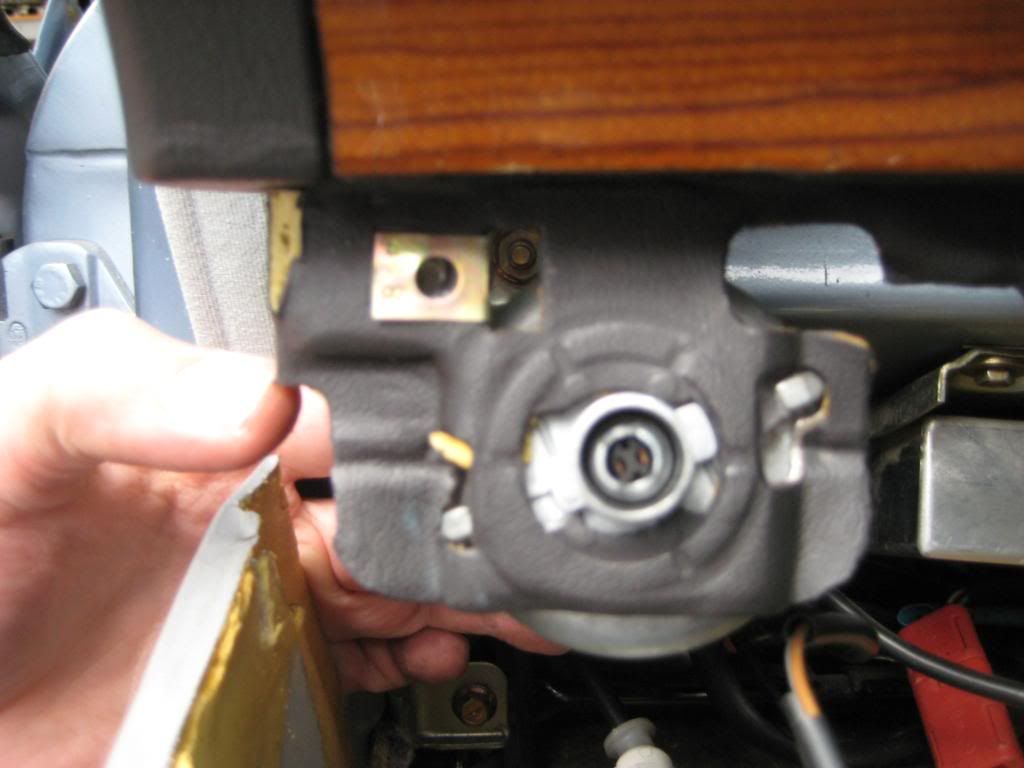 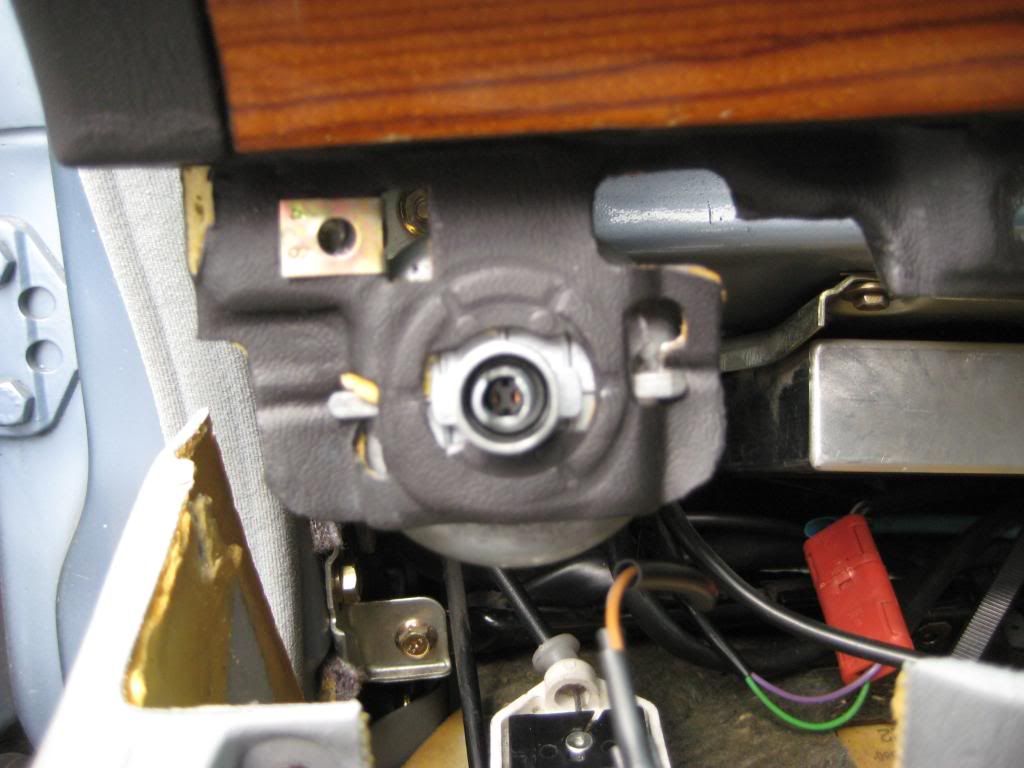 3) I left the driver side bottom cover dangling so I just had to lift it back into place. I pulled toward the driver seat to ensure the outside edge didn't snag in the J-shaped clip. Once at the right height, I guided the outside edge forward ensuring the slot in the dash engaged the J-shaped clip. Sorry, no pictures of this step but here's a reminder of the J-shaped clip - 4) 5 screws that take an 8mm socket hold the lower cover to the dash; 3 by the headlight switch, 2 by the key switch. The screw on the upper right of the key switch has a smaller washer. The other 4 look the same. I can't find pictures of this stage other than this one of the key switch area - 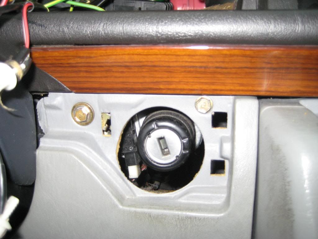 5) Fit the trim plate around the key switch. My trim plate has missing tabs so it's pretty much held on by the rubber curtain that surroungs the key switch cylinder. Slip the narrow end between the steering column housing and dash then push the wide end into place - 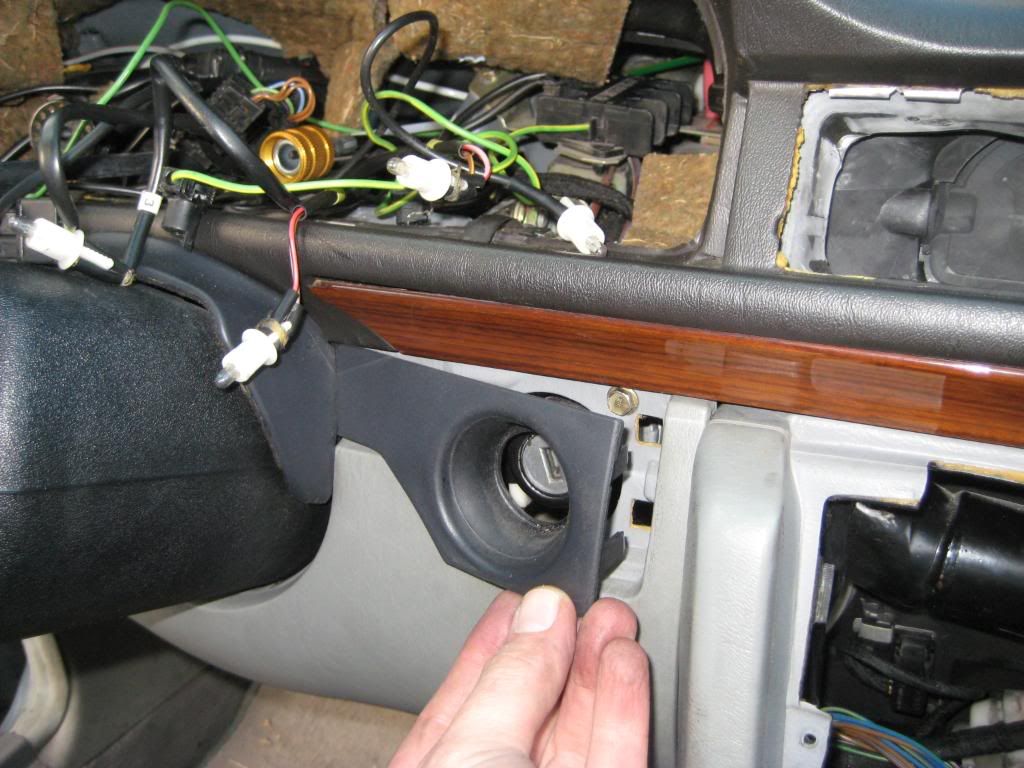 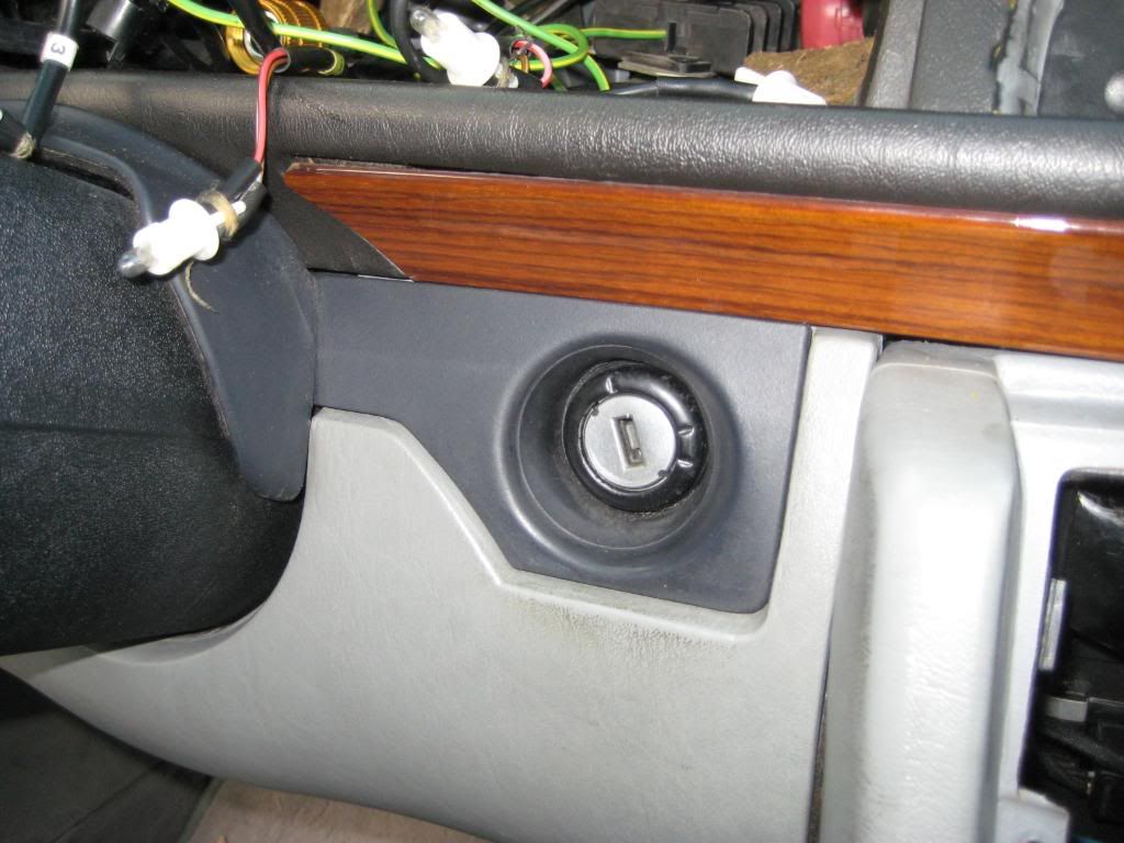 6) Fit the headlight switch illumination bulb into the square socket on the trim plate. My trim plate has missing tabs so it's pretty much held on by the nut that goes over the headlight switch. Slip the narrow end between the steering column housing and dash then push the wide end into place. Hand thread the nut over the headlight switch. I use a 24mm socket and 6" extension as a screwdriver to tighten the nut. Press the headlight knob into place. The Euro headlight adjustment thumbwheel is just for show for now - 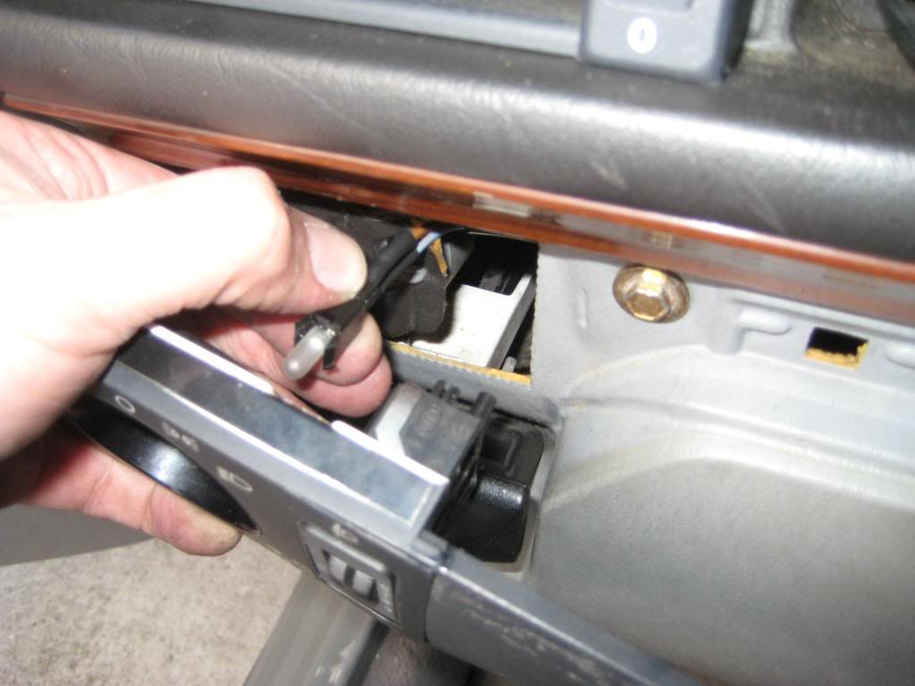 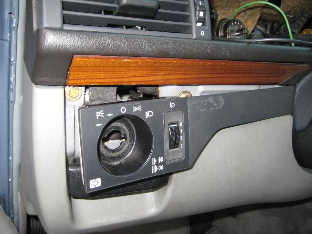 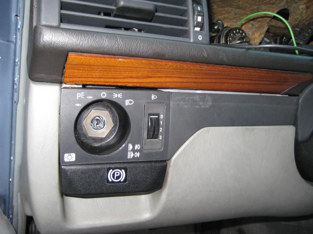 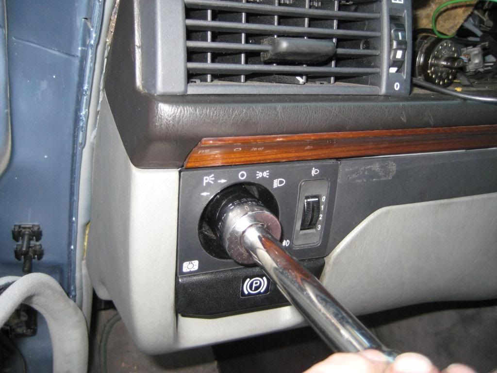 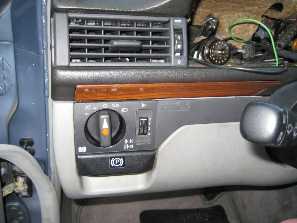 7) Next is the gauge cluster. I start from the passenger side with the wires behind the tach and speedo except for the speedo cable then work from the driver side starting with the speedo cable then the small square connector and big round connector. Note that the flat edge of the center pin of the big round connector faces down. Make sure all the wires and whatnot are in the cubby and not dangling on the dash surface. The glow indicator bulb is on an unusually long lead. Push the gauge cluster into place. The first picture shows the jumble from the passenger side. The second picture shows the jumble mostly attached behind the speedo and tach. The third picture shows the driver side with the speedo cable attached. The fourth and fifth pictures shows the driver side almost in place. The sixth picture shows the gauge cluster in place - 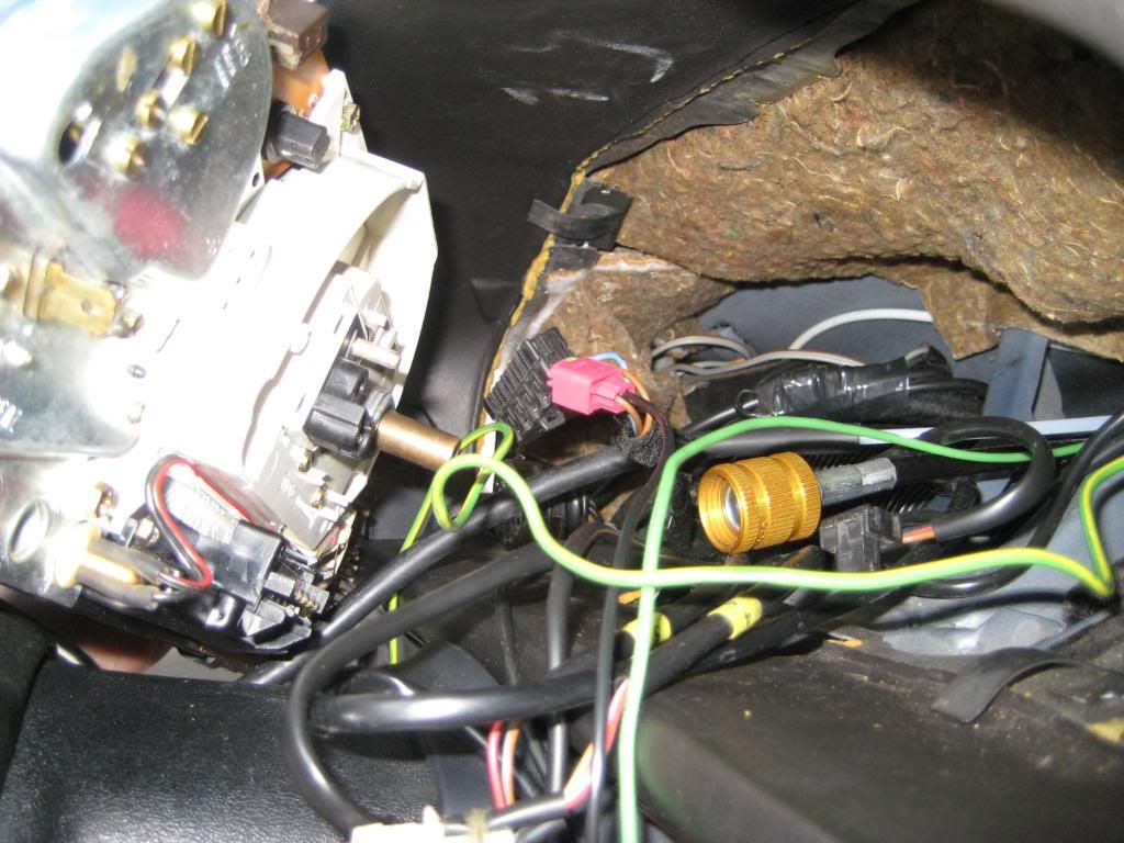 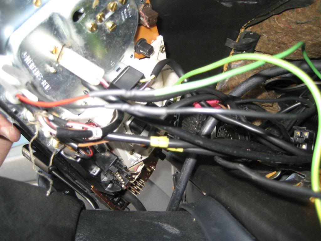 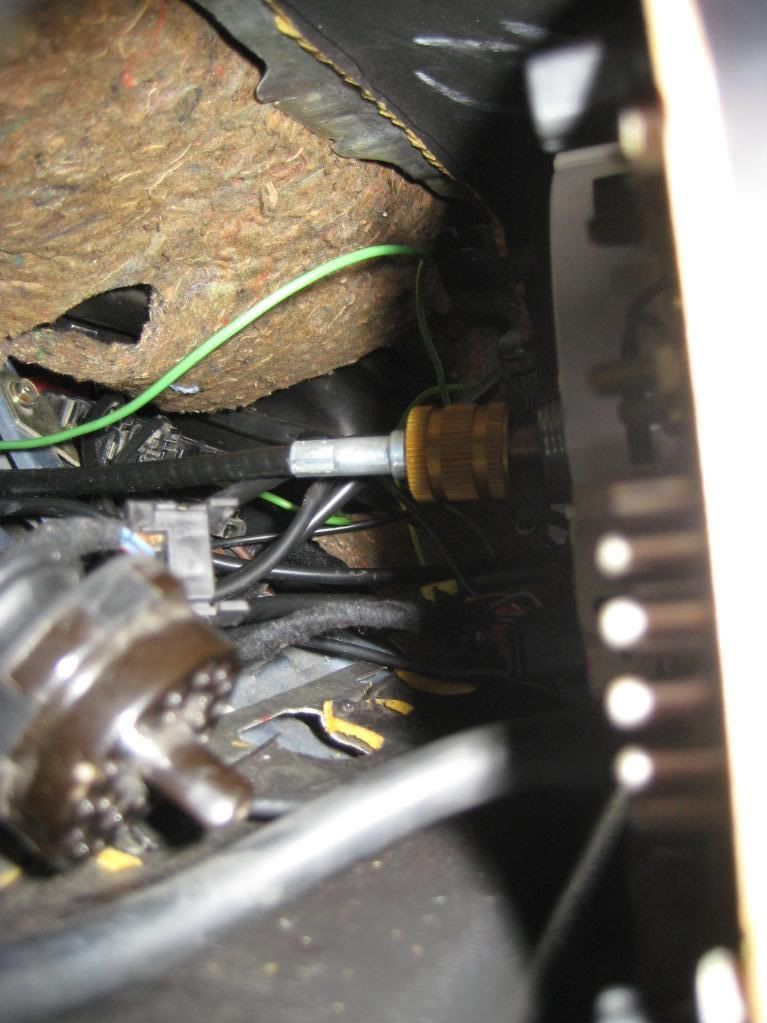 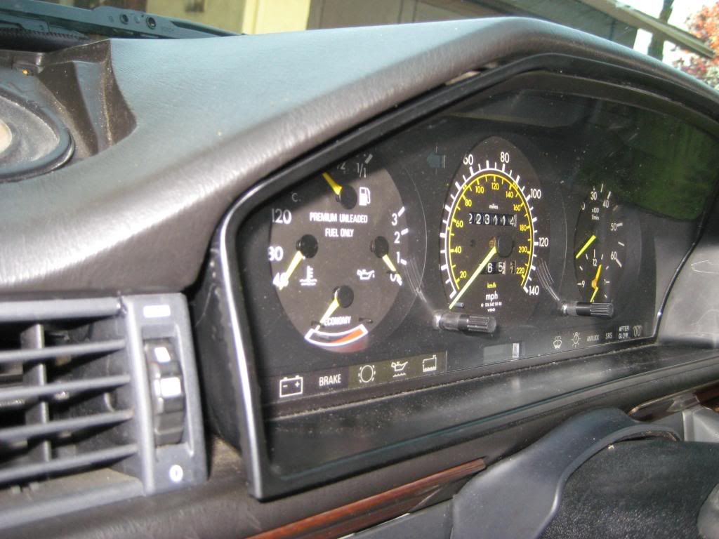 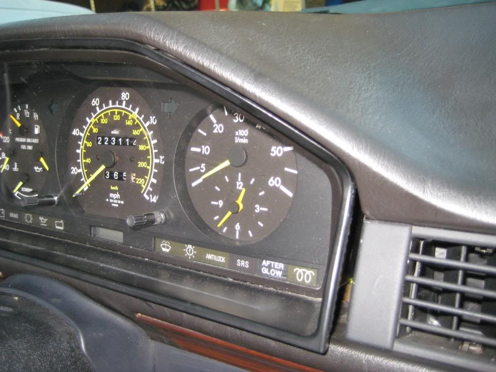 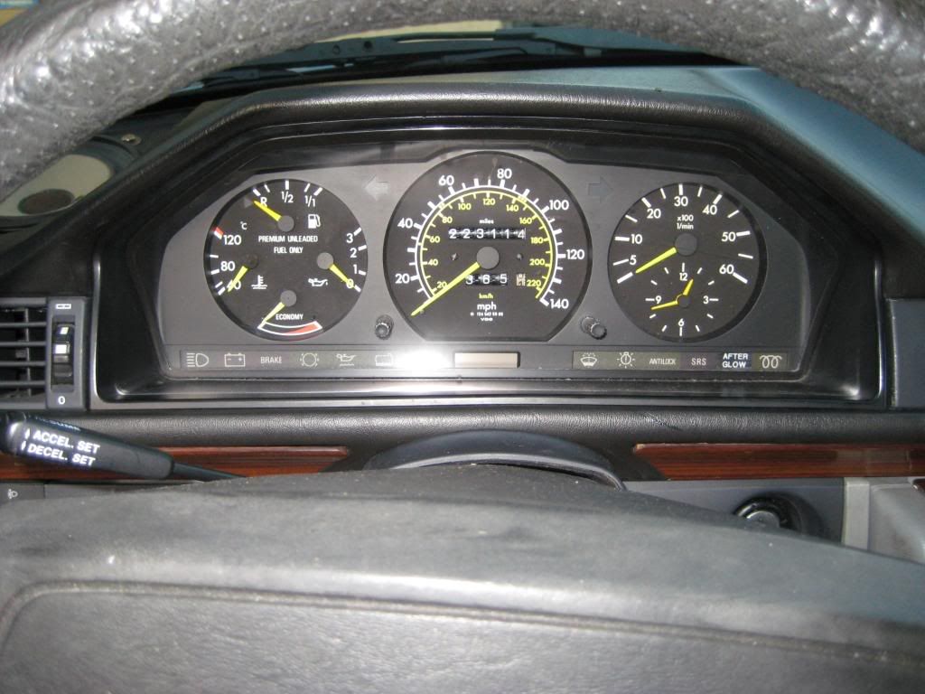 8) Put the driver side vent illumination bulb into the square hole behind the thumbwheel. Align the vent with the duct and push the vent into place - 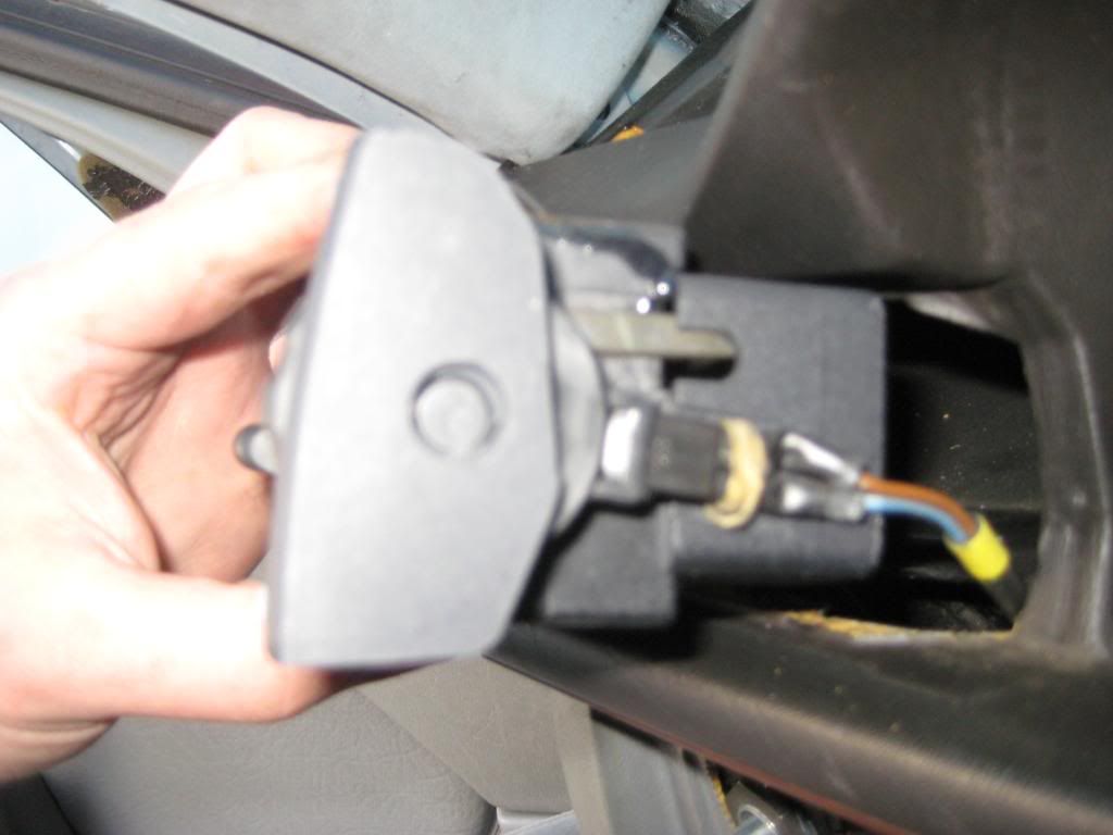 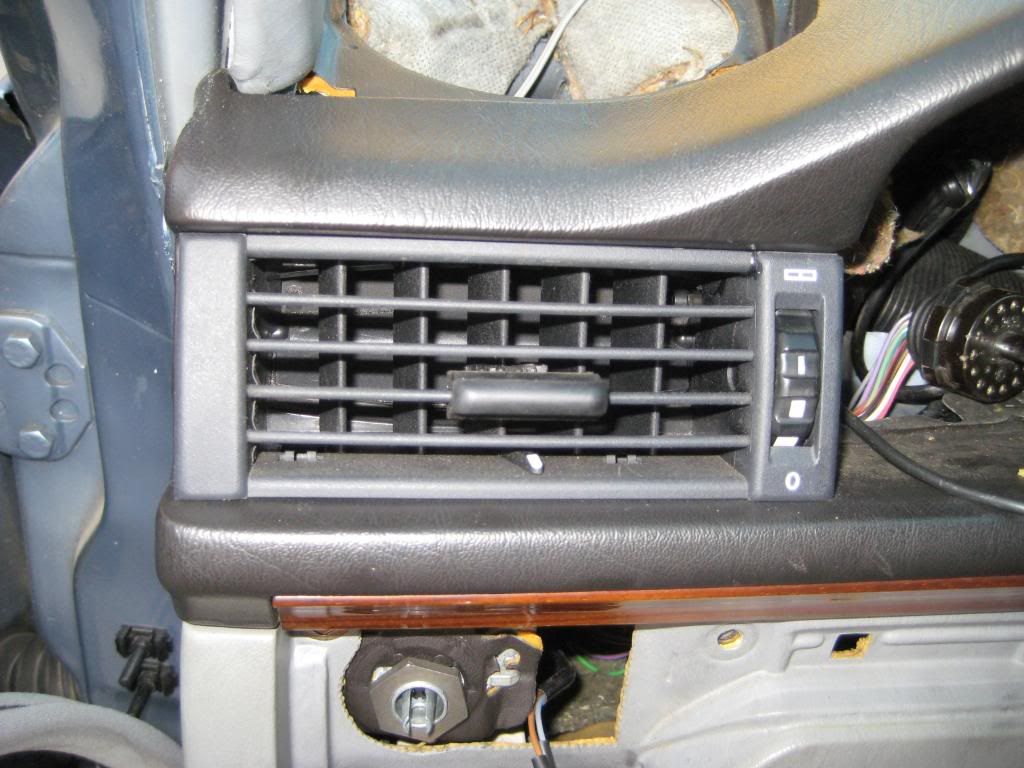 Sixto 87 300D Last edited by sixto; 03-10-2009 at 03:15 AM.
|
|
#3
03-10-2009, 02:52 AM
|
||||
|
||||
|
The dash is solidly mounted to the car. What next? How about the center console area?
1) Note the screw that extends from the unseen side of the center vent assembly. This screw has to engage a plastic receiver attached to a bellcrank that operates the center vent flap in response to the thumbwheel between the center vents. It can't be a coincidence that there is a pilot hole below the screw and a corresponding pilot hole below the threaded hole in the plastic receiver. I did what I could to align the screw and receiver but each is free to move. Whatever. I set the center vent in place. I don't have a picture of the bulb that illuminates the center vent thumbwheel but make sure you thread that through and snap it into the square hole behind the thumbwheel. I don't have a picture of the wire routing but I'm pretty sure there was a slot in the lip that engages the center vent with the duct. As I pushed the center vent into place, I sent a hat pin through the pilot hole under the screw and the pilot hole under the plastic receiver. Like magic both aligned! The screw takes a 4mm hex bit. I didn't feel a natural end to turning the screw so I experimented. At some point the thumbwheel doesn't stay in the fully open position. I backed off until it did. There's a flat top Philips head screws that goes in from the passenger side. None on the driver side. Follow along in pictures - 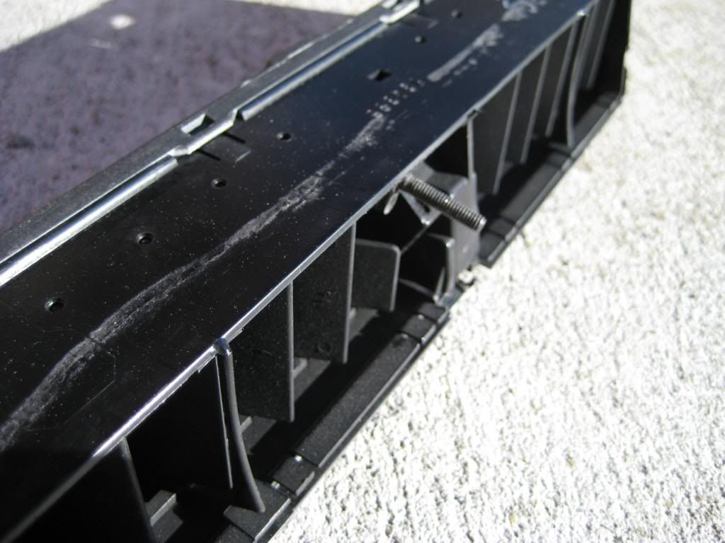 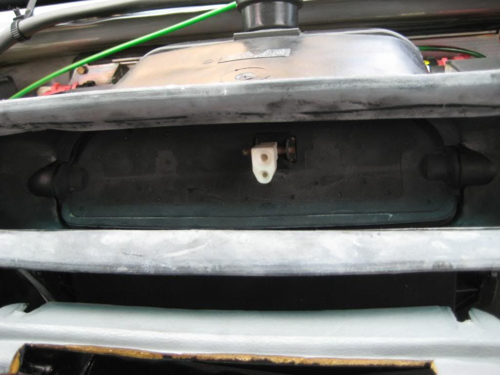 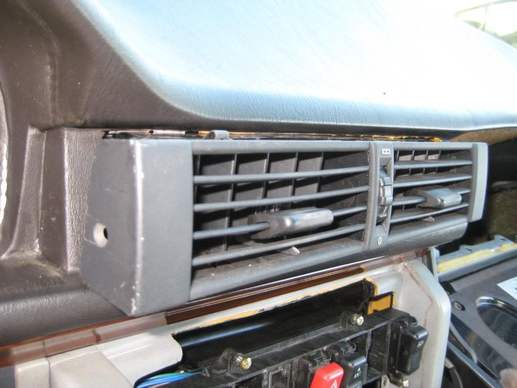  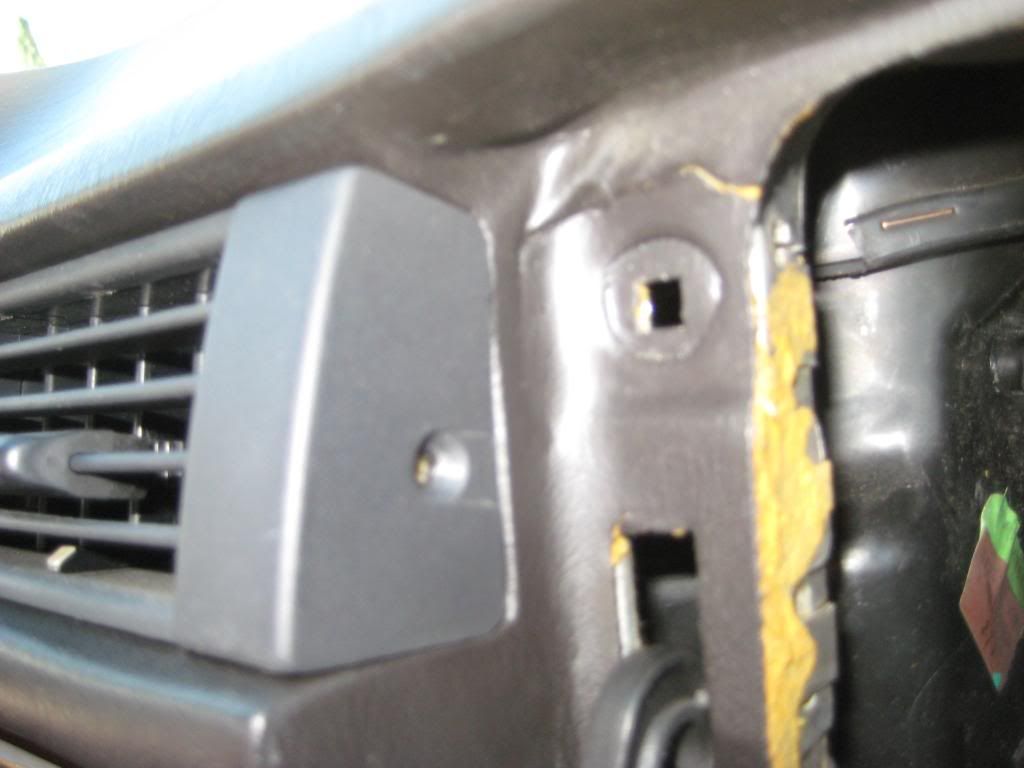 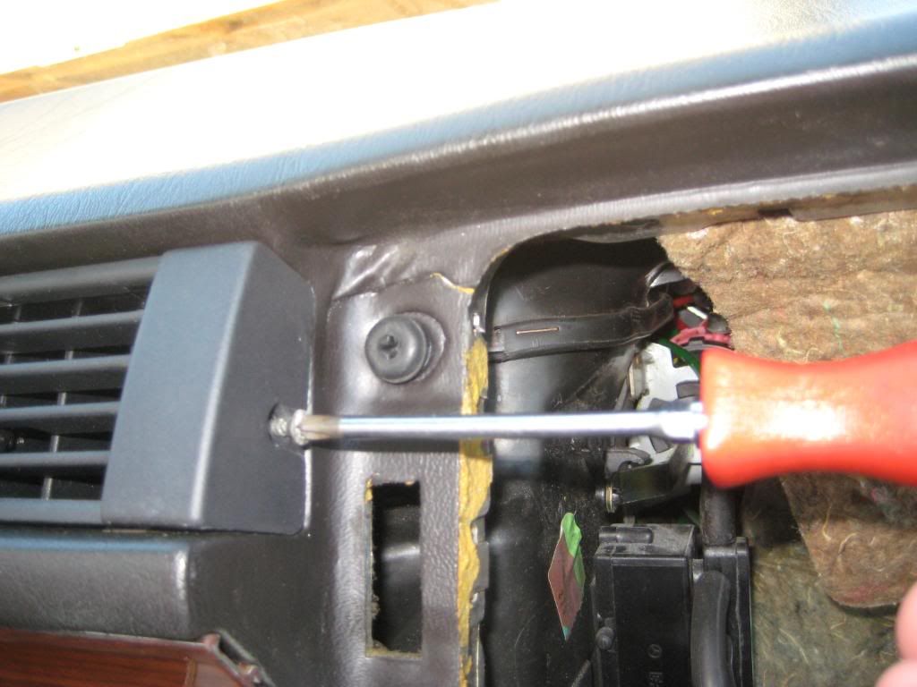 2) I completely botched this step so I'll document it but find another method. Removing the center console switch panel was an absolute PITA. I bent the panel more than I thought was reasonable and it somehow didn't break. I couldn't bend it back into place though. Neither the ears on the sides of the panel nor the tabs in the console are beveled. I set the driver side ear on the driver side tab then used a putty knife as a ramp to get the passenger side ear on the passenger side tab. The passenger side ear broke off! Oh well. The first picture shows the driver side ear. The second picture shows the driver side tab. The third picture shows where there used to be a passenger side ear - 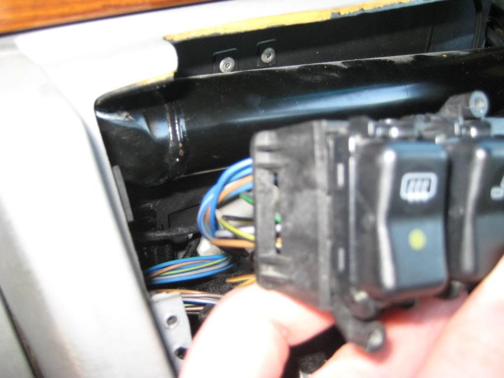 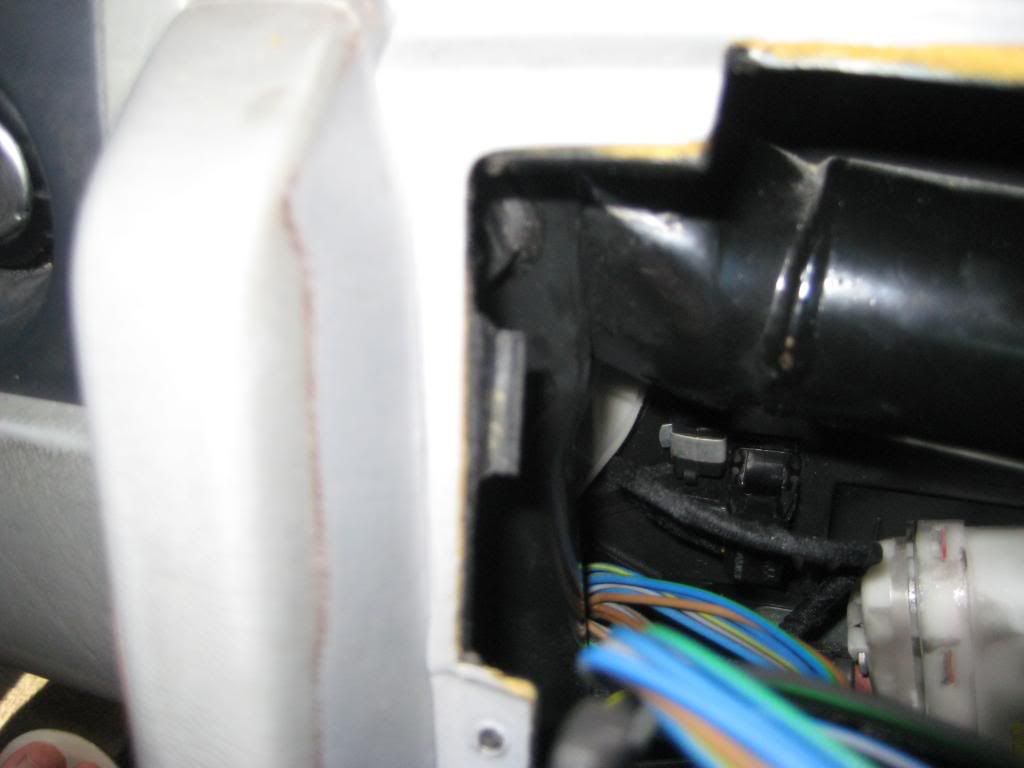 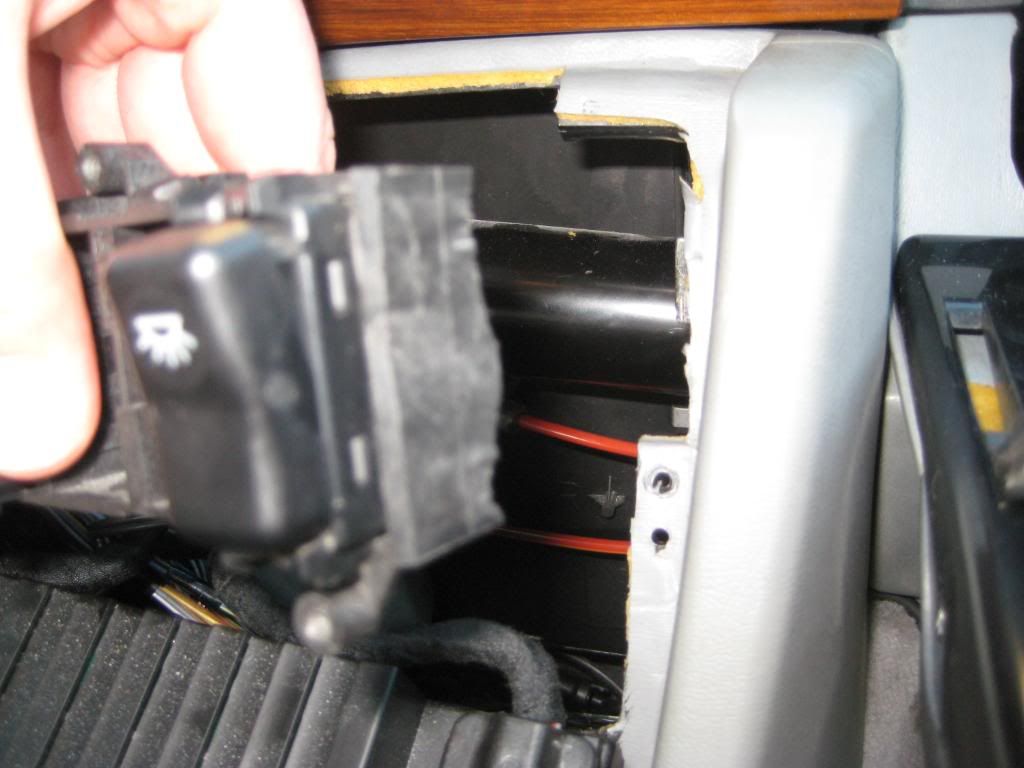 3) Fortunately the switch panel is well secured to the ACC control panel so all is not lost. The first picture shows the 2 electrical connectors for the ACC control panel. The second picture shows the connectors going on the control panel. The third and fourth pictures show the connectors on the driver and passenger side of the control panel. The fifth picture shows the control panel and switch panel in place. The sixth picture shows the 6 Philips head screws in place. 2 bigger screws towards the bottom hold the control panel to the console, the remaining 4 screws hold the switch panel to the ACC control panel (yes, I had to undo most of this work to refit the recirc switch) - 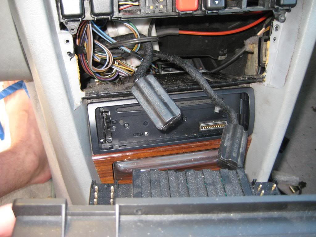 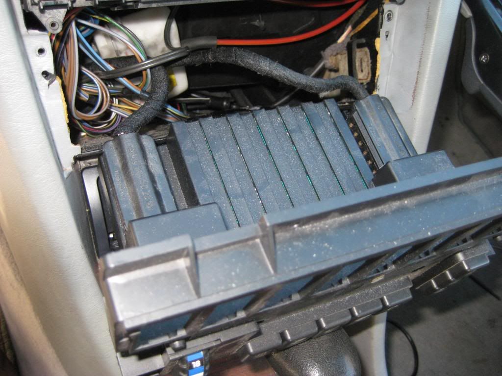 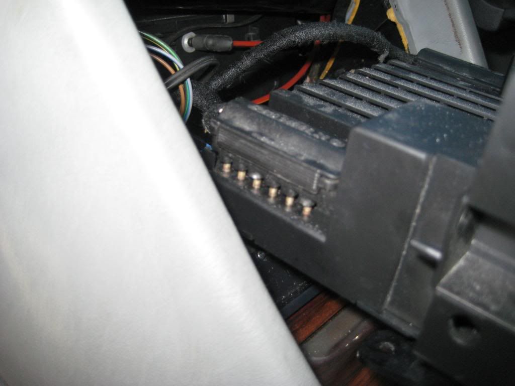 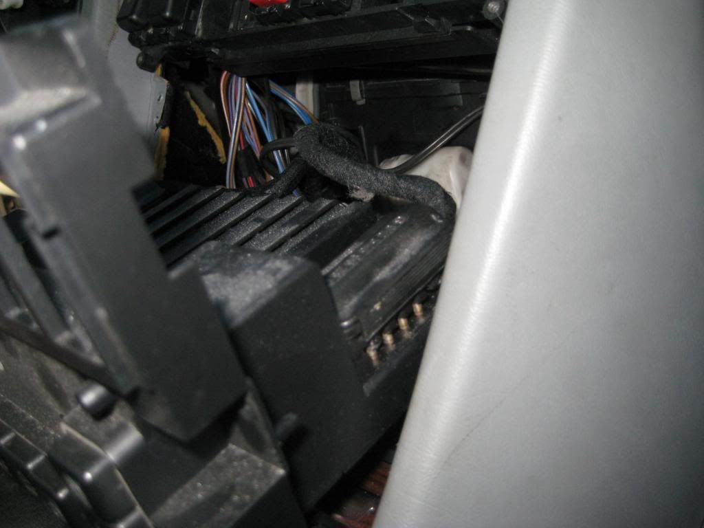 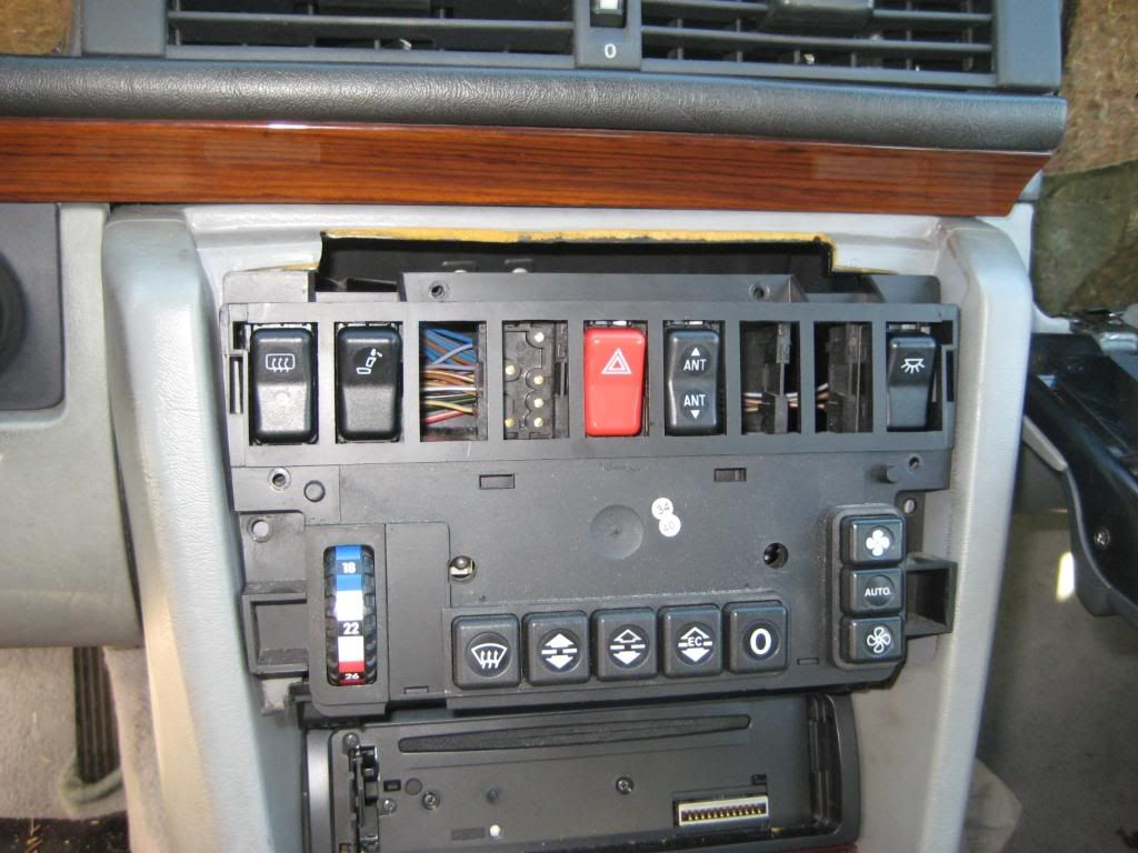 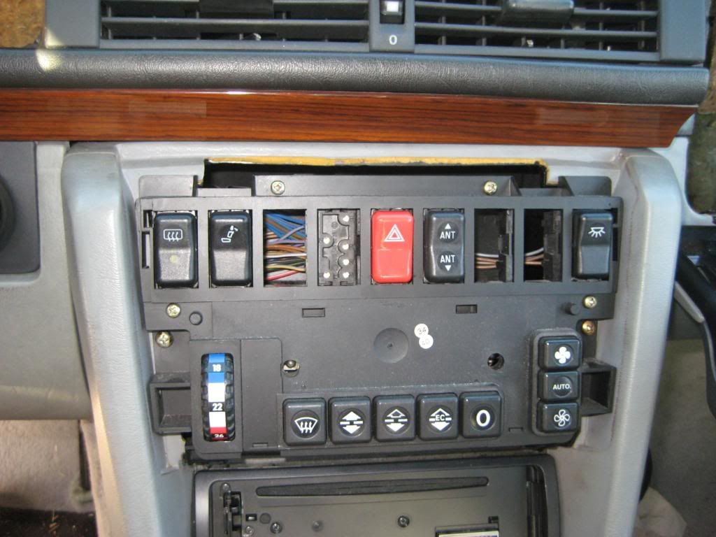 4) Then the wood trim panel goes on. The first picture shows the hinge tabs along the top of the trim panel and the slots in the console into which they... uhh... slot. The second picture shows the trim panel swinging down into place. The third picture shows two screw holes along the bottom of the trim panel above the radio. The fourth and fifth pictures show the Philips screws going into place. The sixth picture shows the radio faceplate in place  - -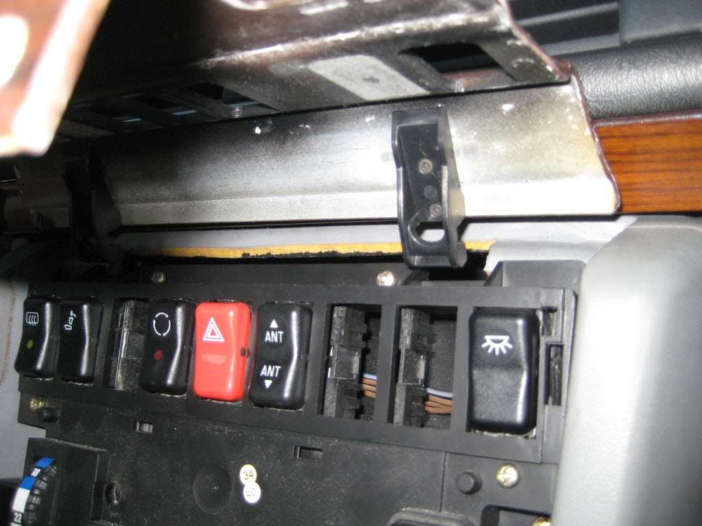 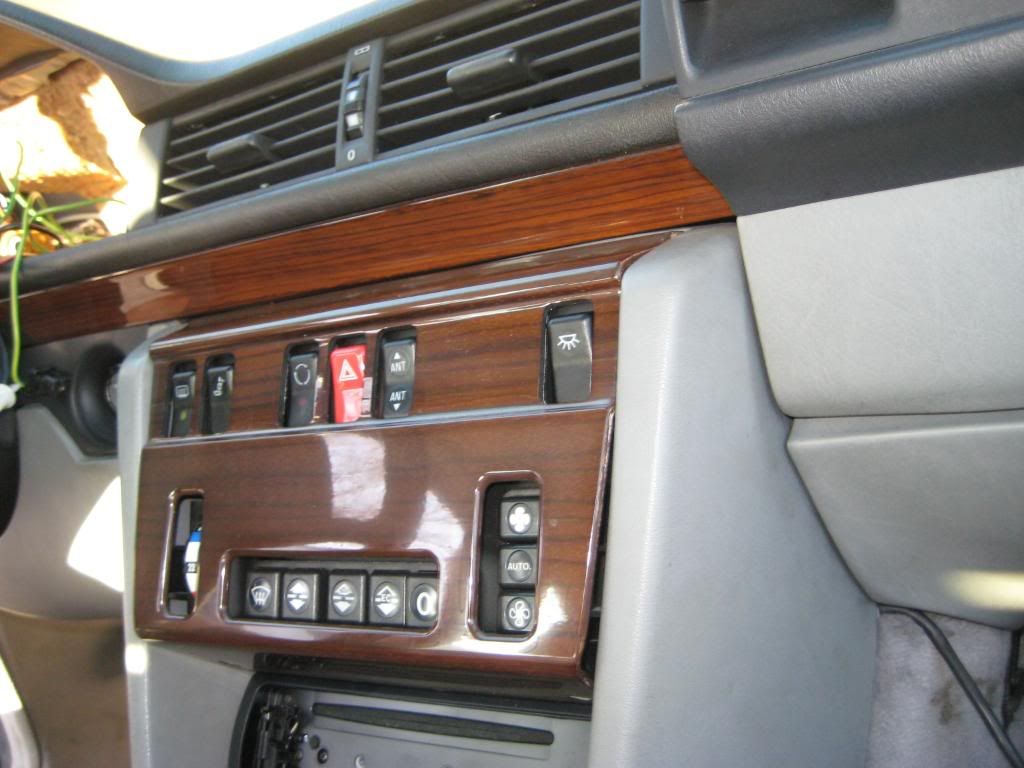 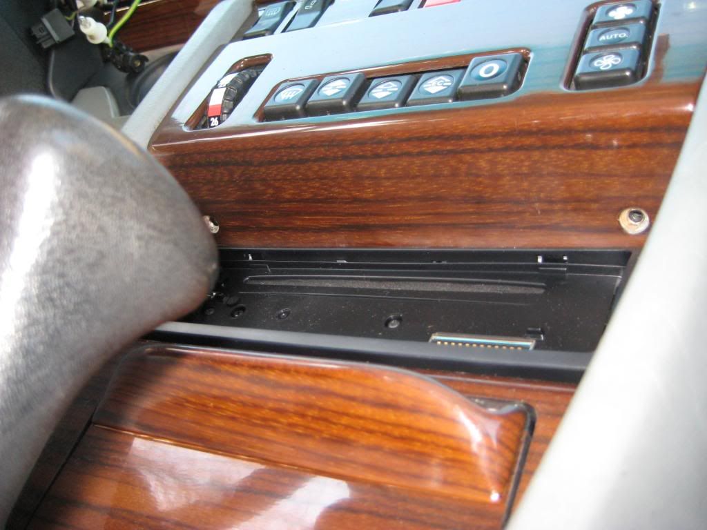 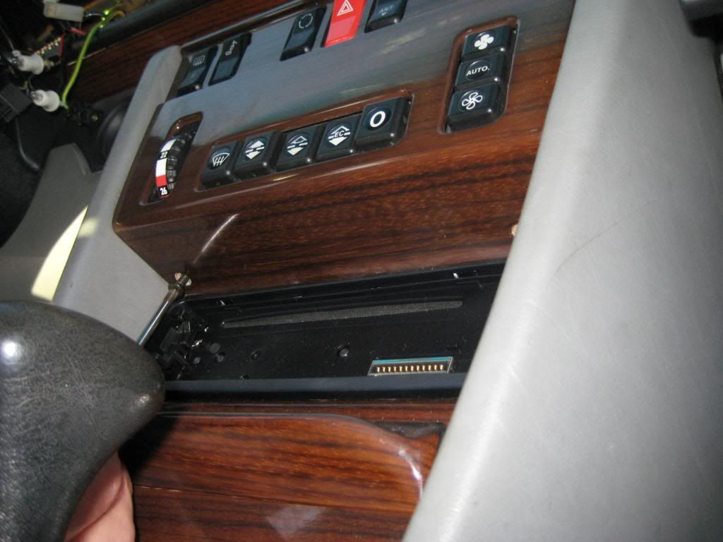 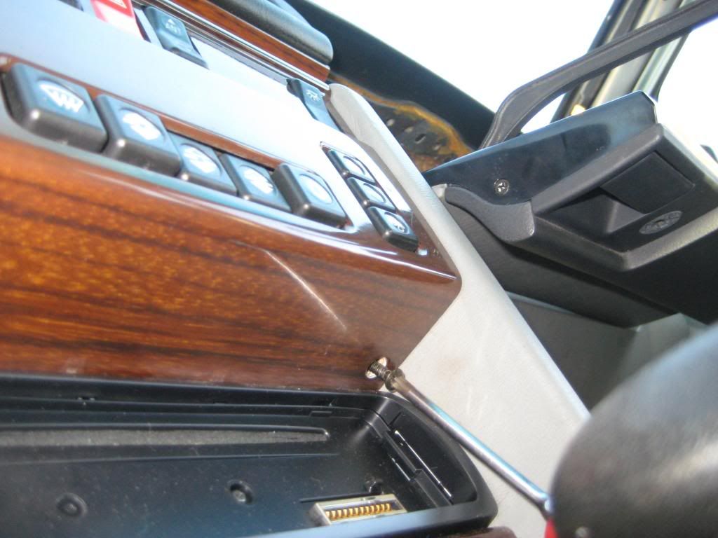 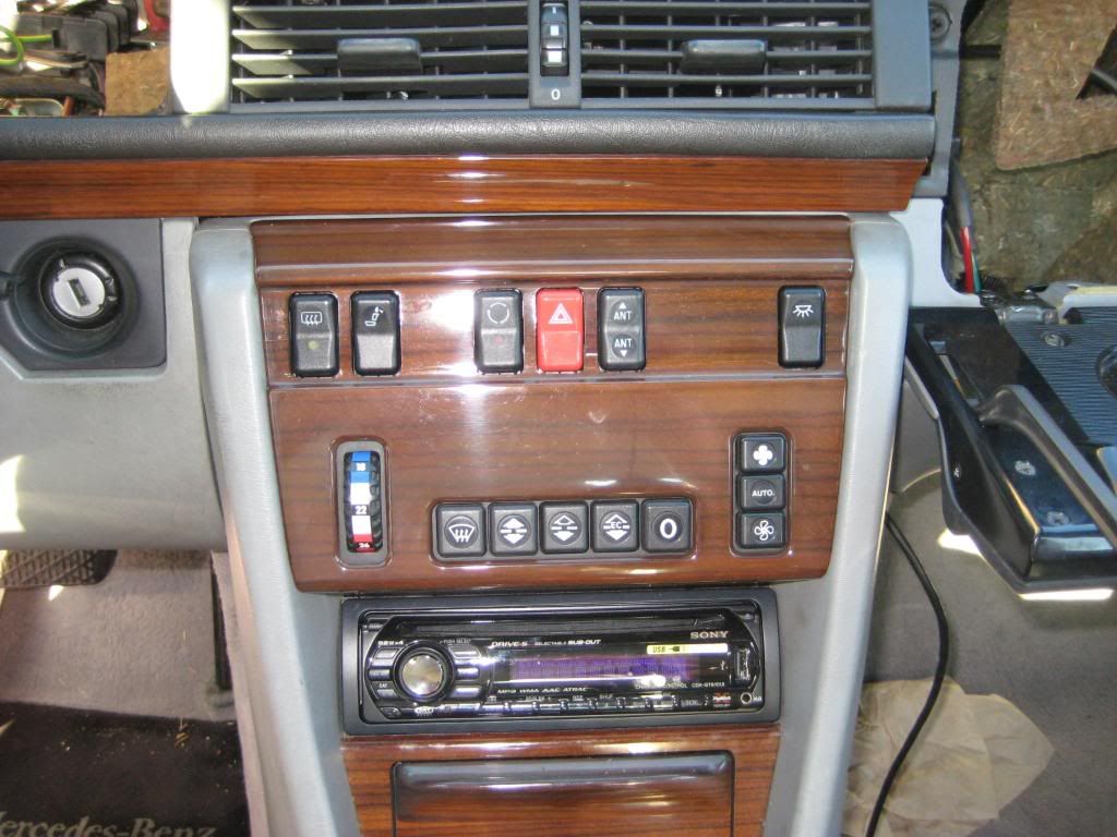 Sixto 87 300D Last edited by sixto; 03-10-2009 at 03:22 AM.
|
|
#4
03-10-2009, 02:55 AM
|
||||
|
||||
|
Now to button up the passenger side.
1) I released the lower dash panel from the dash and let it rest on the floor. Unlike the driver side that kind of stays in place, the passenger side is held to the bulkhead by a couple of plastic tabs. I set the tabs in the corresponding slots and lifted the panel to hook the trailing edge on the glovebox hinge ledge. The first picture shows the trailing section of the lower panel clipped to the leading section of the lower panel. The leading section has tabs that engage the bulkhead and vertical panel that somehow attaches to the side of the center console. There's a screw from below that keeps these sections attached. I had loosened the screw during disassebly so I had to reattach the panels. The second picture shows the aspirator blower and the clip that holds it to the lower panel. There might not be enough slack in the rubber hose to attach the aspirator blower to the panel until the panel is lifted off the floor. There's lots of room to put the aspirator blower in place through the glove box cavity once the lower panel is in place. Just don't forget to do it! The third picture shows the lower panel sections engaged (I put a proper black screw in place of that silver screw). The tabs that engage the bulkhead are not engaged. The fourth picture shows how the left tab engages the bulkhead. The fifth picture shows both tabs engaged. The sixth and seventh pictures show the 2 holes in the lower panel that align with brackets that hang down from the dash. Gold colored screws with captive washers that take an 8mm socket are used here. The eighth picture shows two gold colored Philips head screws with captive washers that go down just below the lower edge of the passenger side dash vent cavity into the lower panel - 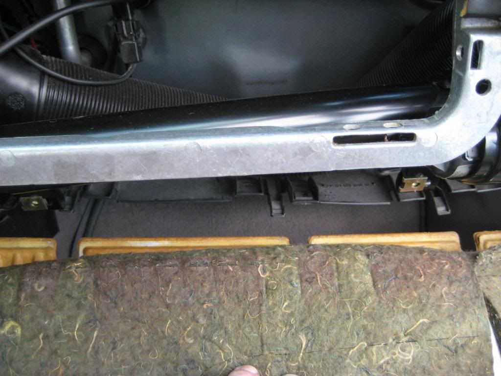 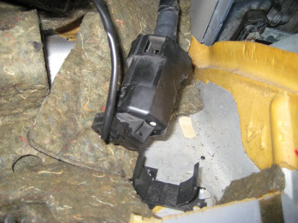 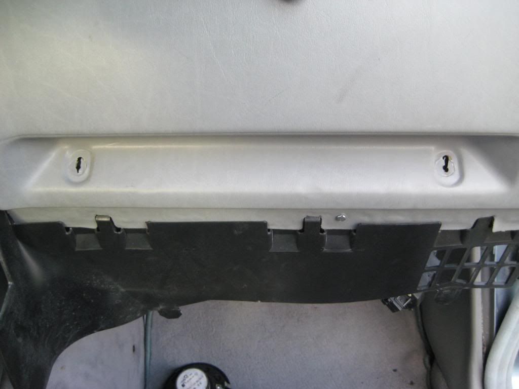 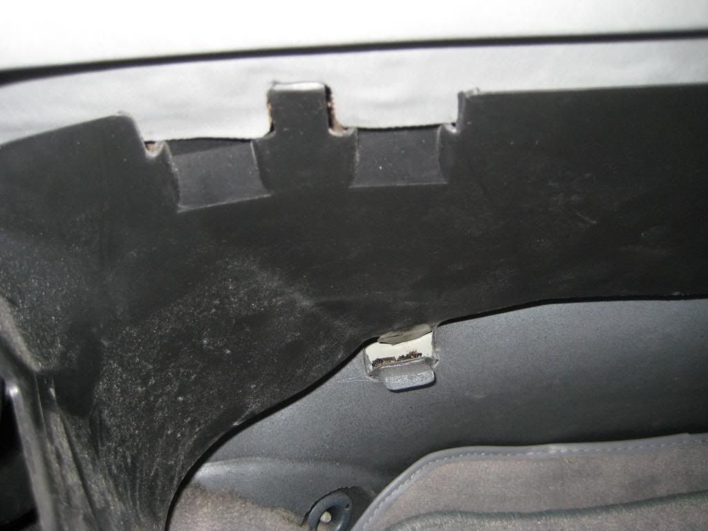 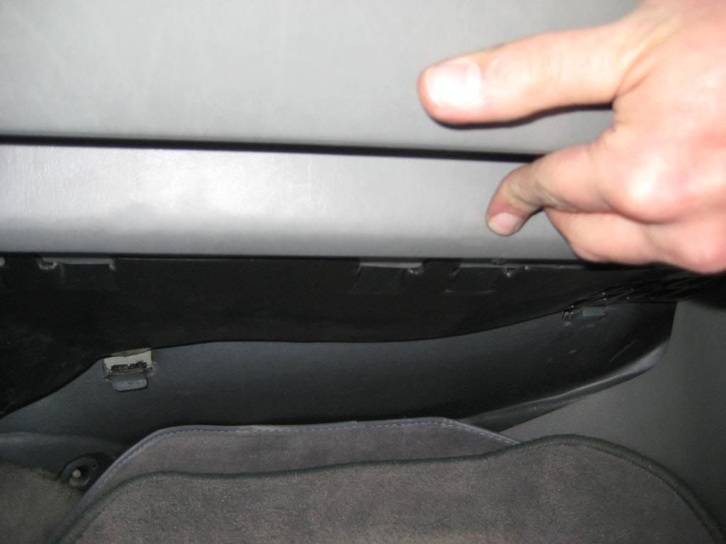 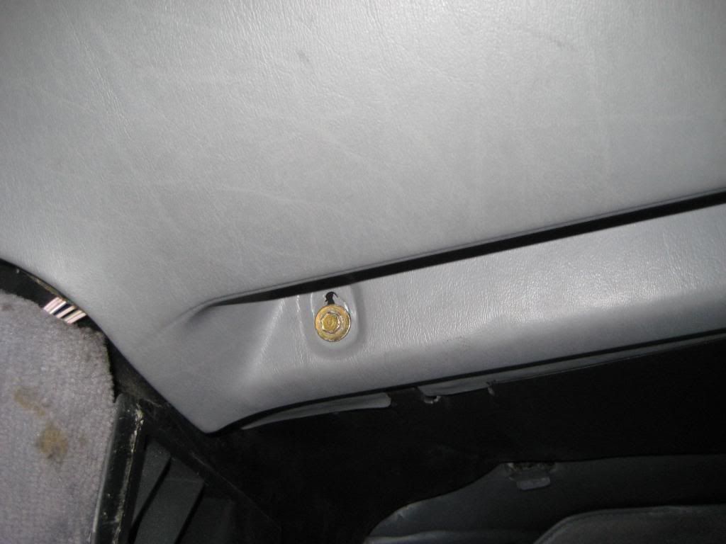 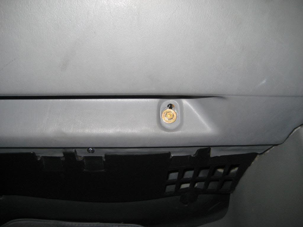 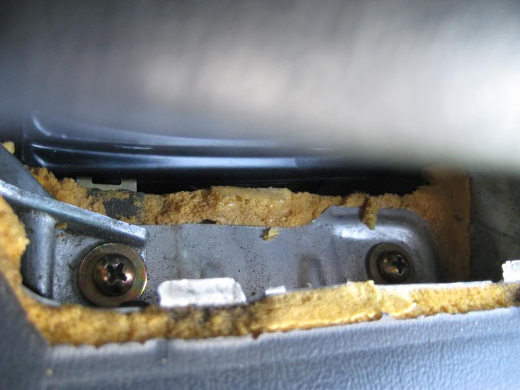 2) There is a double layer of padding in the lower panel under the glove box. I had to peel back one layer from the trailing edge where the lower panel meets the glovebox hinge ledge of the dash so the glove box hinge holes would align. The first picture shows a nut clip going over the hinge ledge. the hinge ledge is actually 2 ledges. The clip goes over the lower ledge. The first picture also shows a black Philips head screw going horizontally towards the passenger side, just above and to the passenger side of the hinge. The second picture shows the clip in place. The third picture shows a glovebox hinge set over the ledge. The fourth picture shows two black Philips head screws set loosely in place to waiting for adjustment of the glovebox door. The same procedure is used on the other hinge. The fifth picture shows a screw going horizontally towards the driver side on the driver side edge of the glove box cavity - 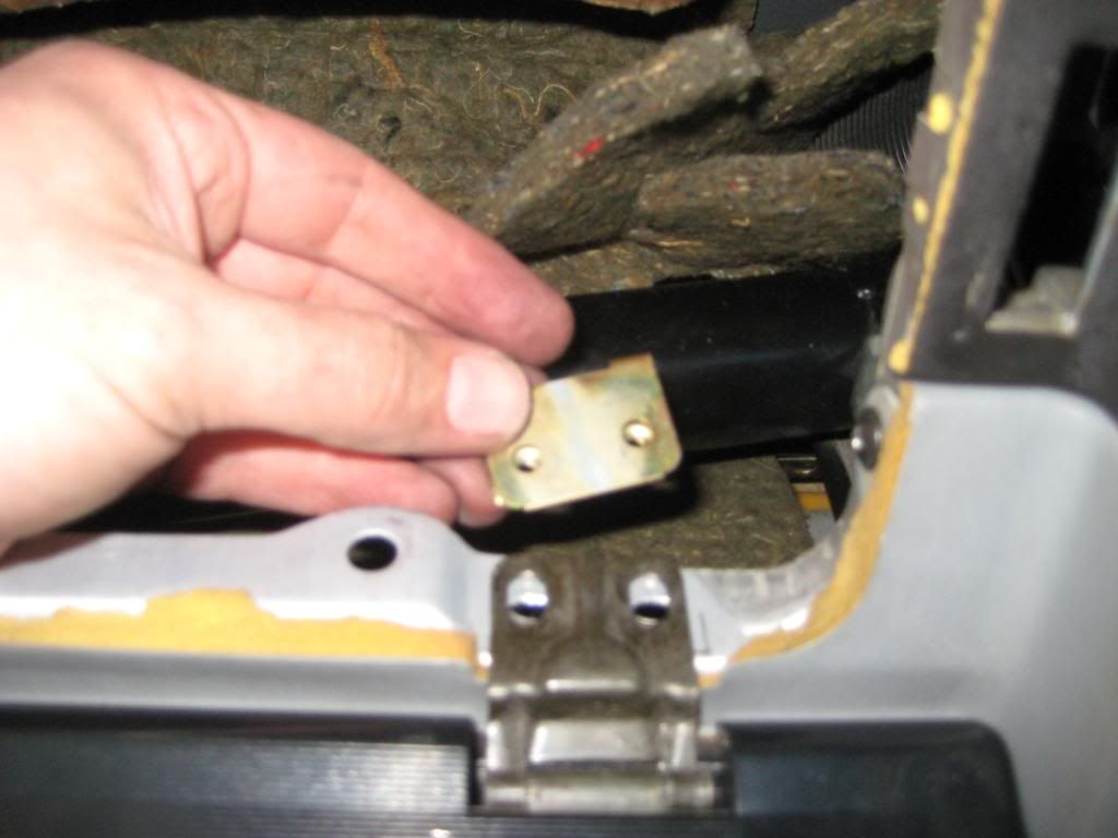 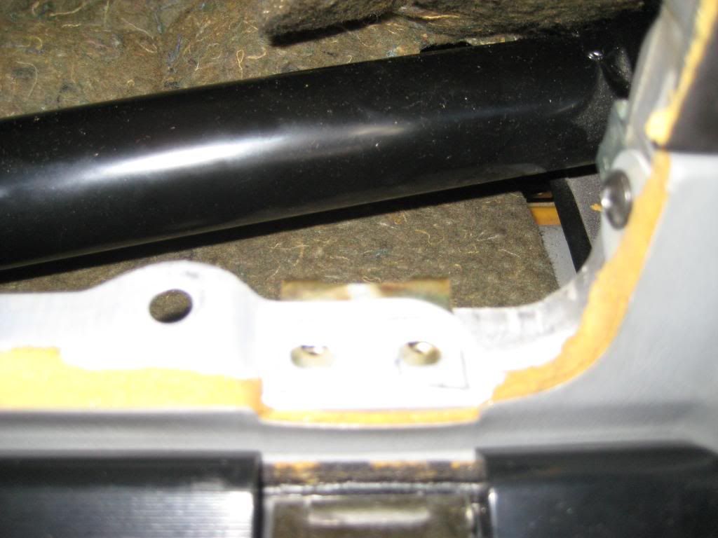 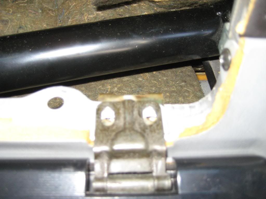 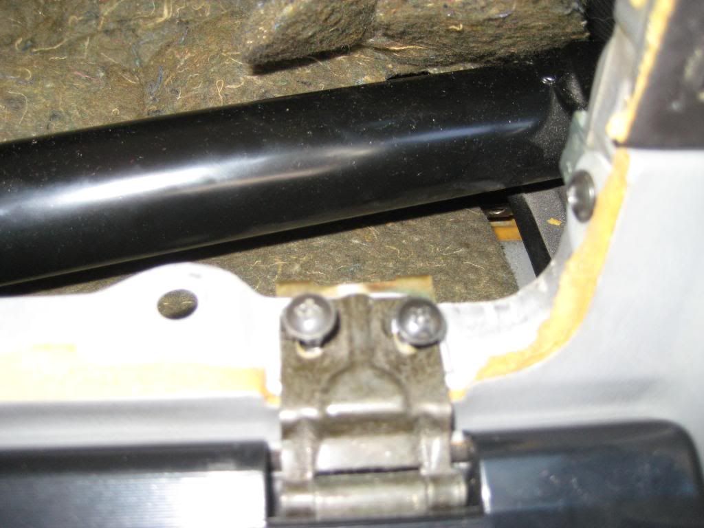 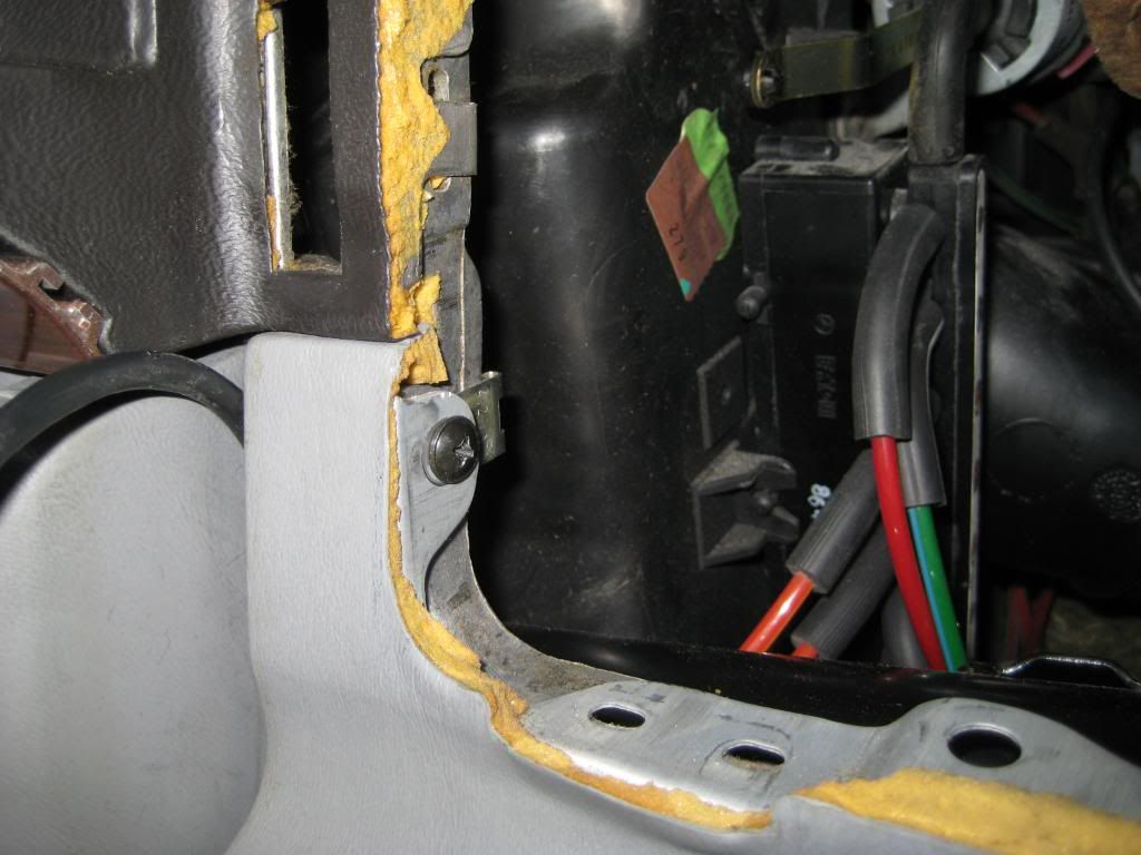 3) I pushed the passenger side duct through the opening a little bit to ensure good engagement with the vent. Then I set the vent thumbwheel illumination bulb in place in the square hole. Then I engaged the vent in the duct and pushed the vent into place - 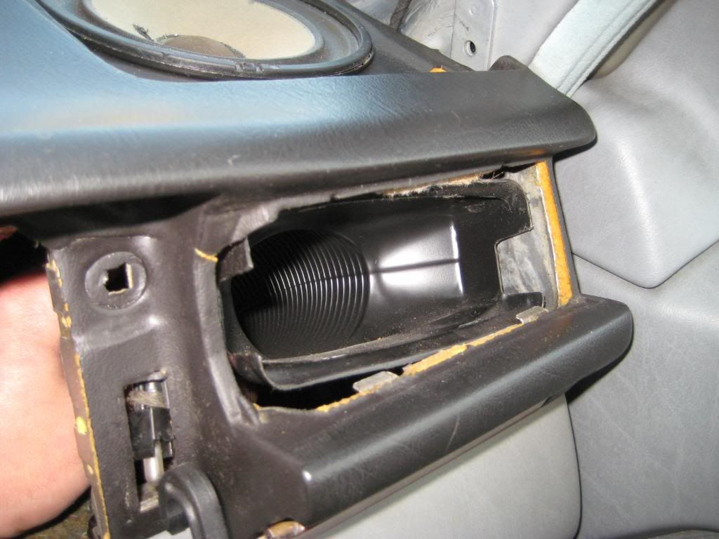 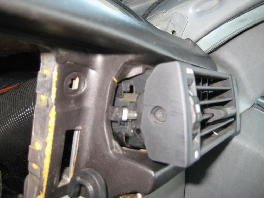 4) The glovebox door stops fit into the square holes above the limit arm slots. The guides come off by unscrewing the center pin which is a plastic Philips head screw then prying out the plastic nut with tabs that fit into the square holes in the dash. It works out to be a toggle bolt arrangement but, sorry, I don't have pictures of the removal process. I do have pictures of the installation process. Final adjustment is done before the glovebox liner goes into place. Turn the plastic screws in or out so the glovebox door is even with the surrounding dash. The slots in the hinges suggest another dimension of adjustment but in my car the hinges would not would slide into a preferred position as the screws were tightened. The first picture shows the pair of toggle bolt glovebox door stops. The second through fourth pictures show a plastic nut going into the square hole in the drivers side. The fifth and sixth pictures show a plastic nut going into the passenger side. The seventh and eighth pictures show the driver side plastic screw going into the nut. The ninth and tenth pictures show the passenger side screw going into the nut - 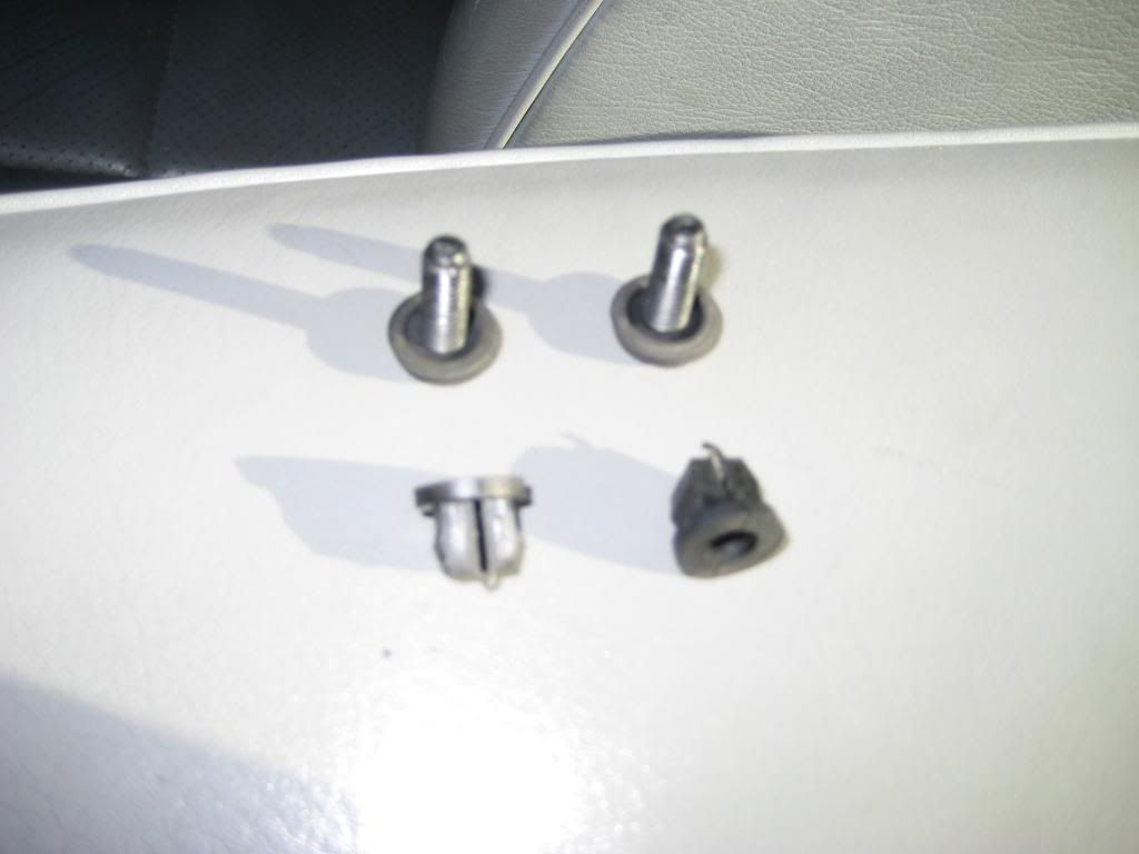 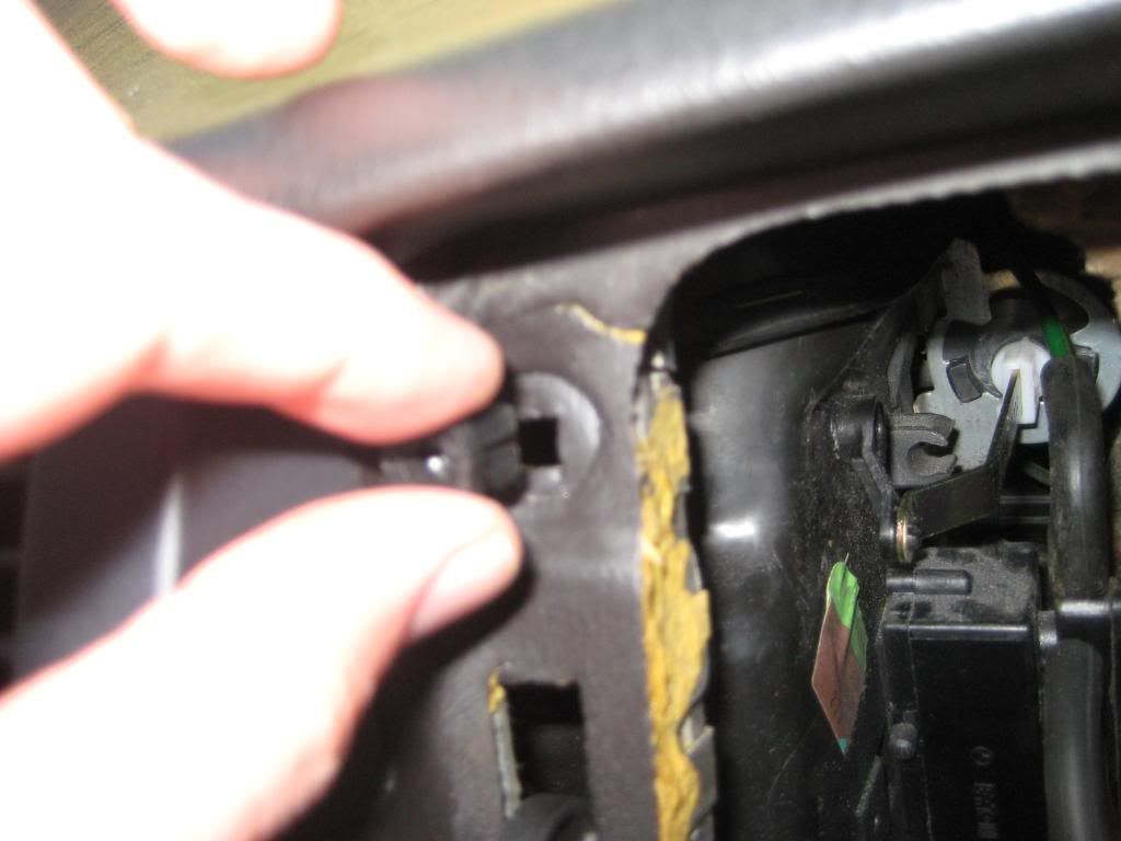 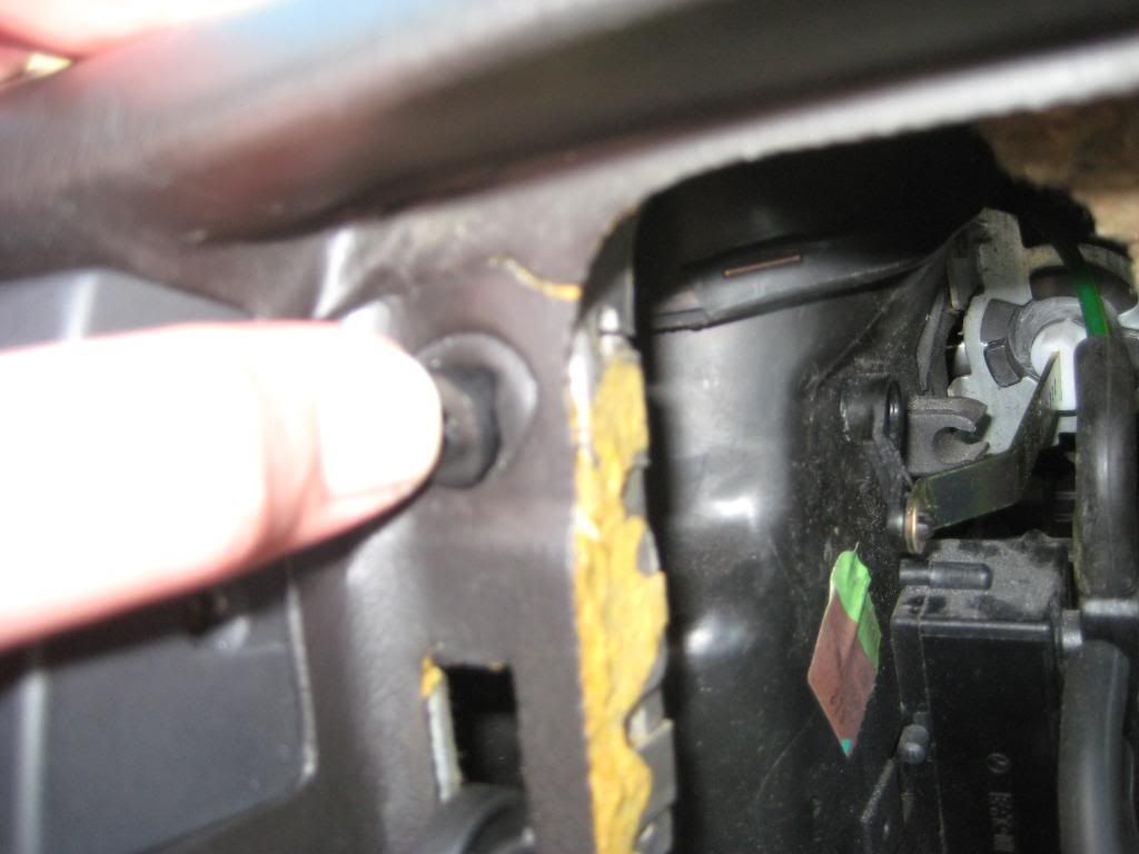 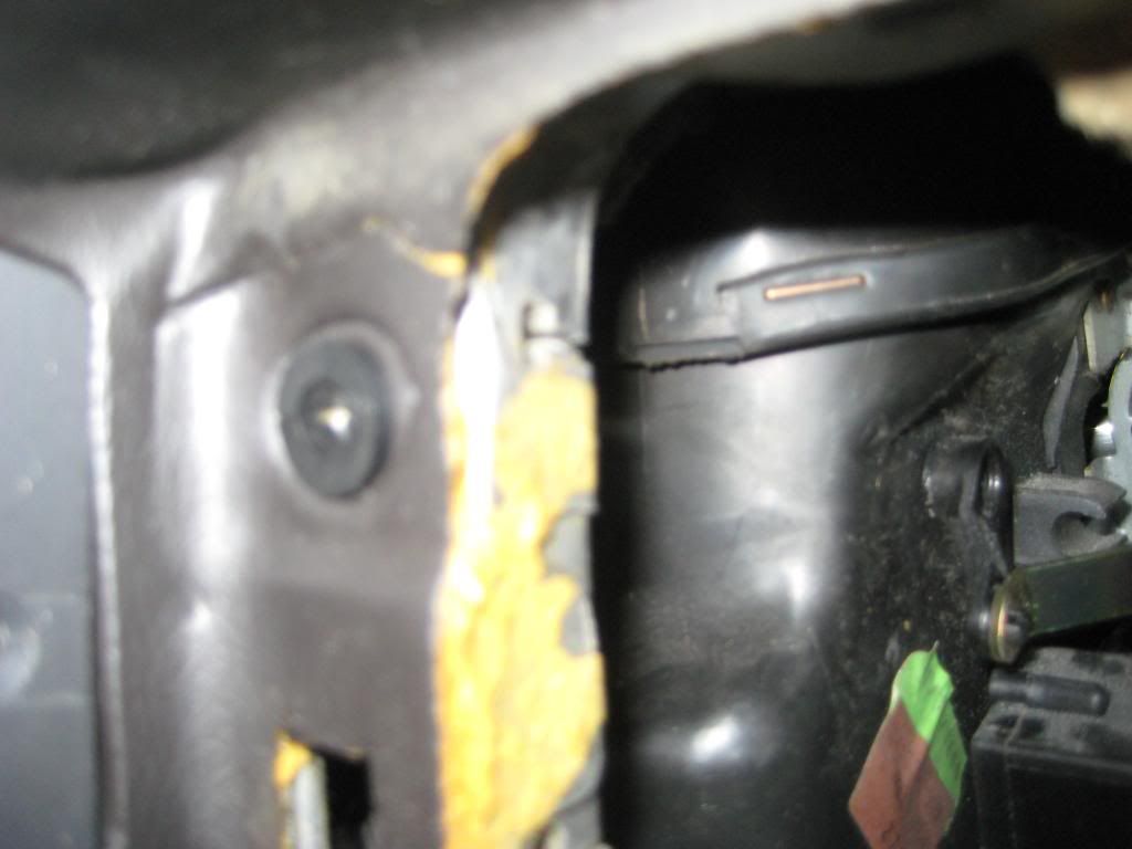 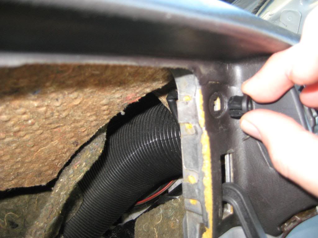 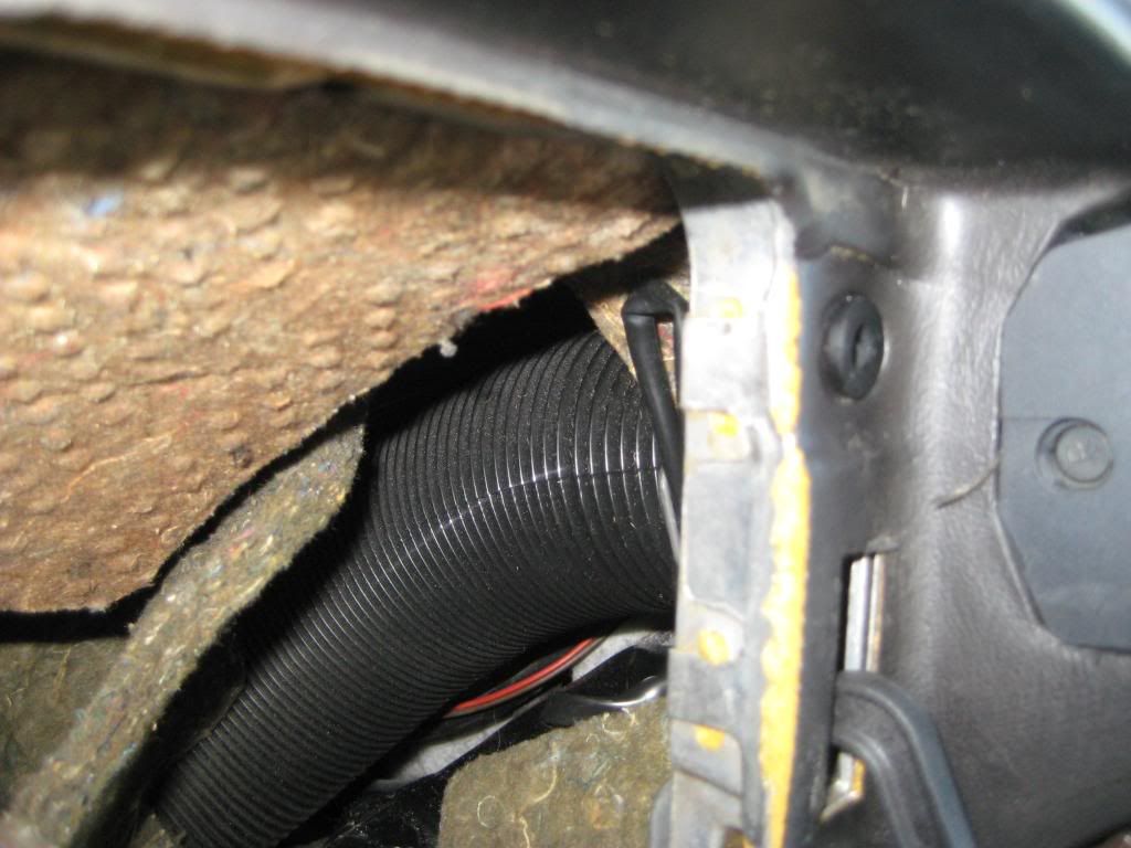 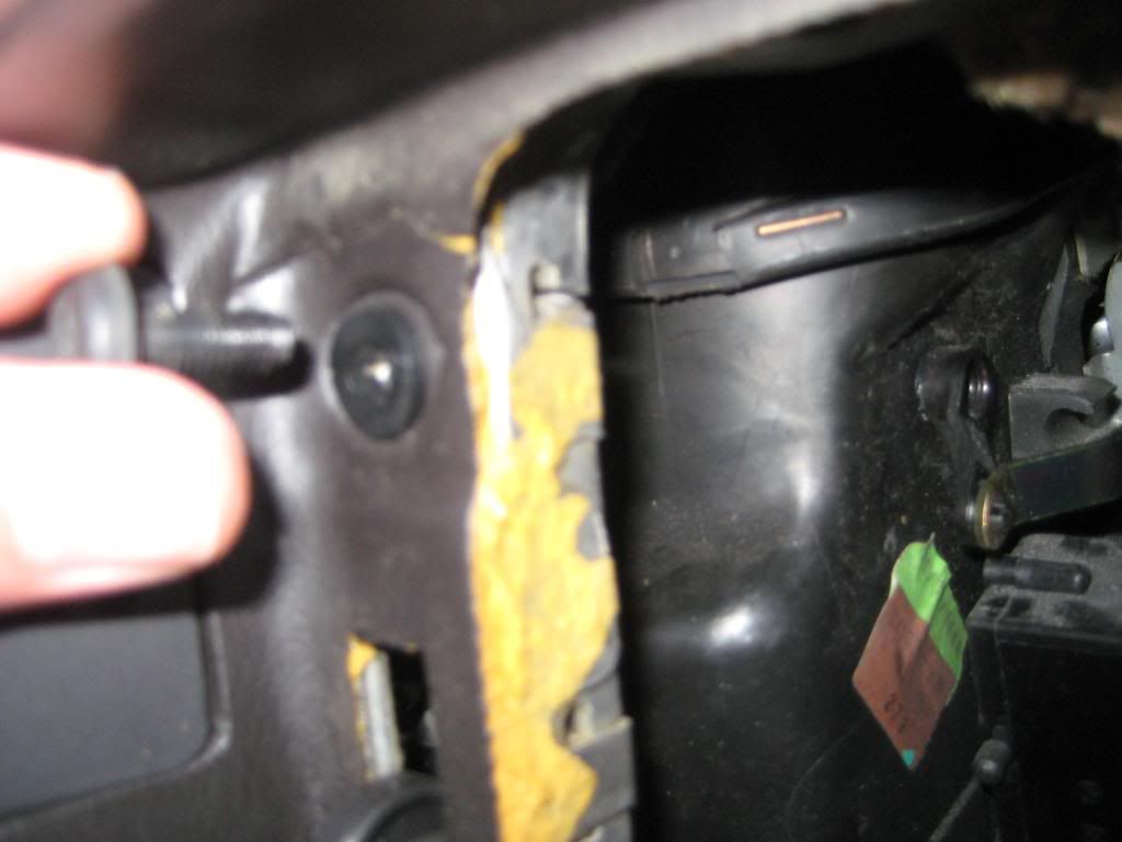 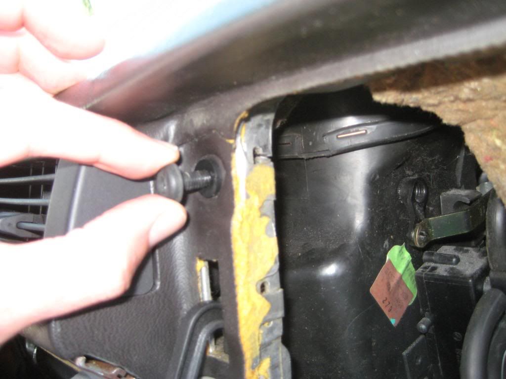 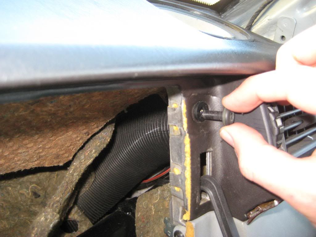 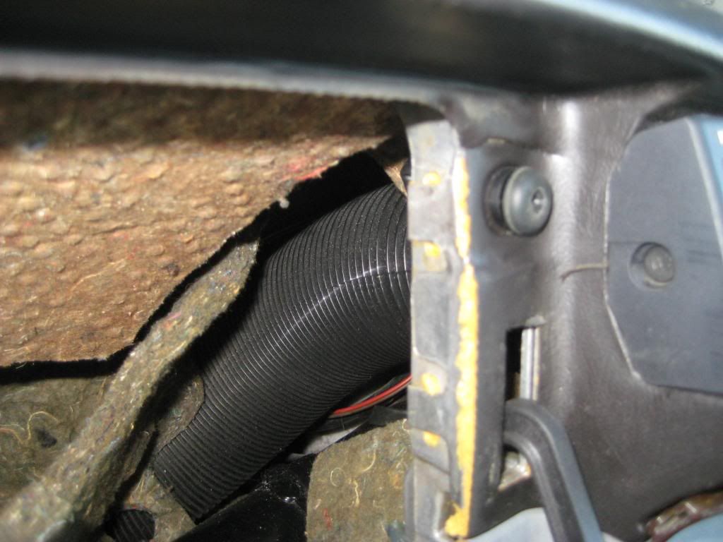 Sixto 87 300D Last edited by sixto; 03-10-2009 at 03:31 AM.
|
|
#5
03-10-2009, 02:57 AM
|
||||
|
||||
|
5) If you try to close the glove box door at this stage, you'll note the driver side limit arm catches the ACC airbox. Don't worry, there are guides to prevent that contact. In retrospect, the glovebox door striker is installed after the glovebox liner is in place so there's no way to adjust the hinges much later than this step.
The first picture shows the guides. The second picture shows the driver side guide going into place. Note the thicker end of the guide as viewed from the cabin goes towards the top. I noticed one side of the guide has a small tab and the tab side was on the dash side while the side without a tab was on the cabin side. At least that's how it was in my car. I don't think it matters where the tabs end up as long as the guides function. The second through sixth pictures show the left guide going into place. I used small screwdriver to gently guide the guide into place then to restore the guide to shape. The seventh through ninth pictures show the passenger side guide going into place (yes, I inadvertently started the driver side guide with the tab side towards the cabin) - 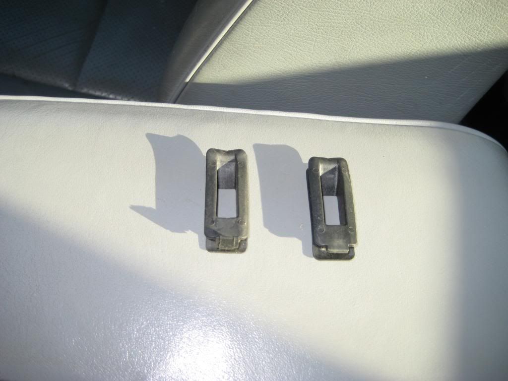 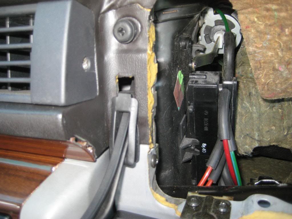 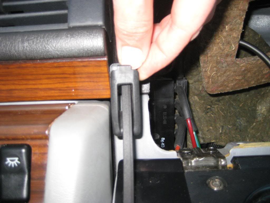 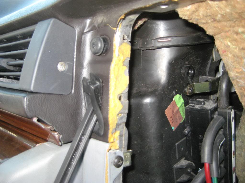 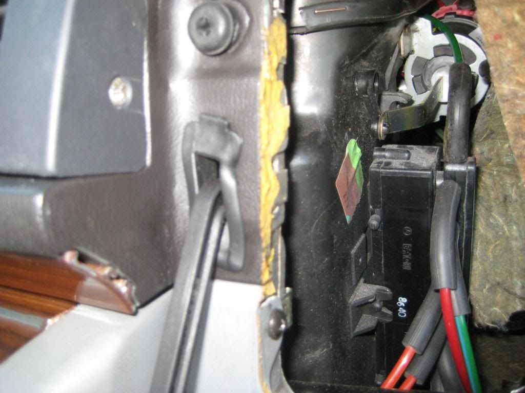 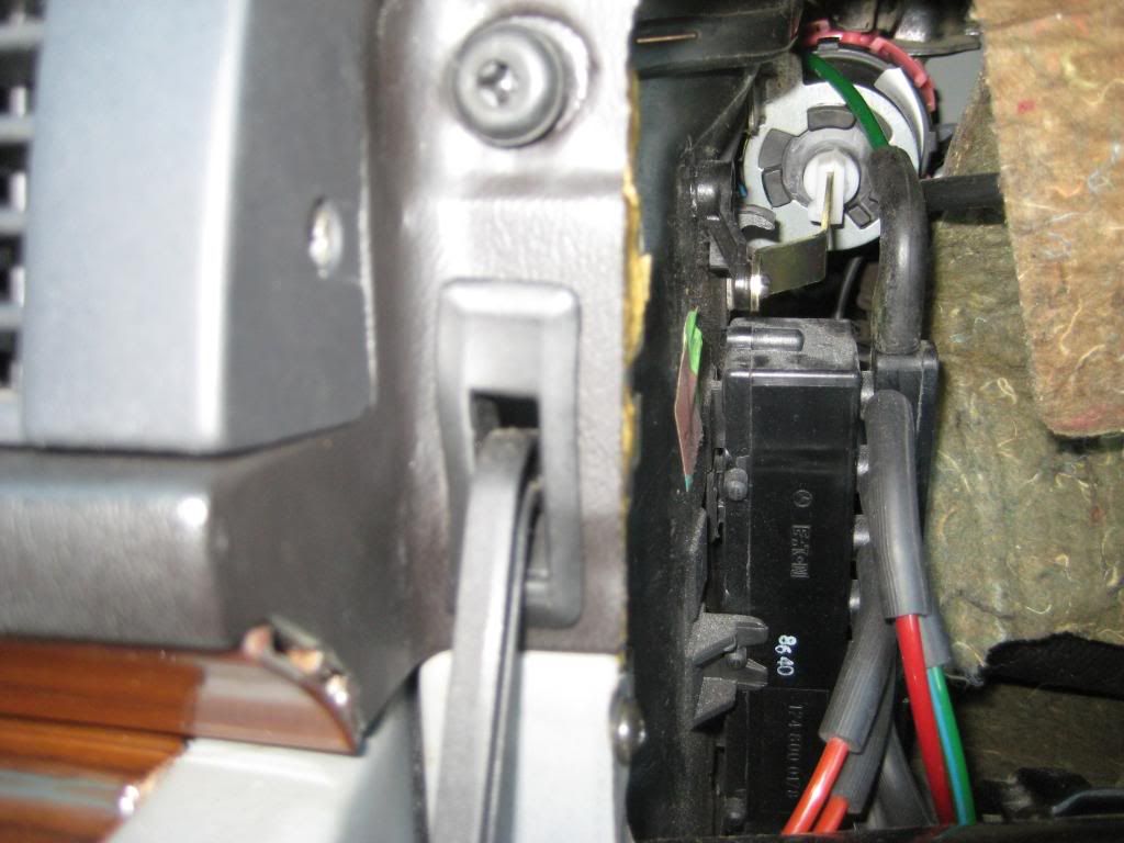 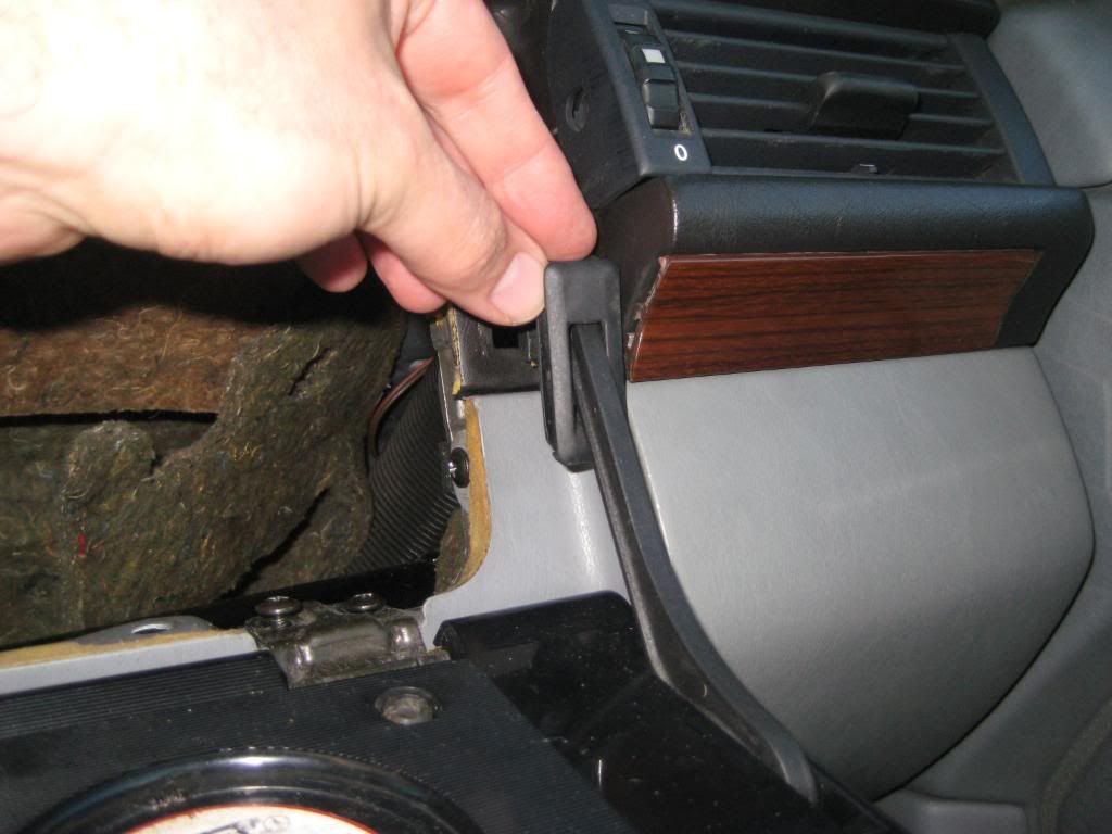 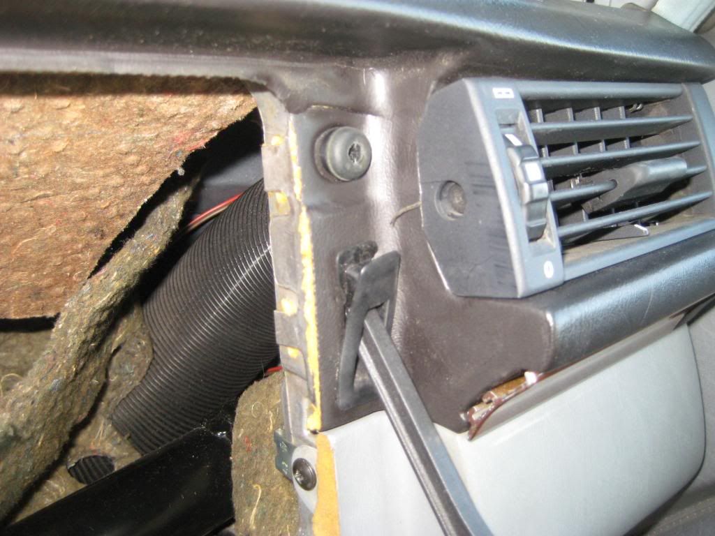 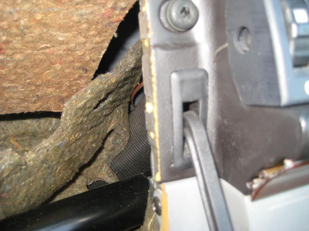 6) The first picture shows a nutclip that slides onto the upper ledge of the glovebox frame in the dash. The second picture shows the nutclip going into place. The third picture shows the nutclip in place - 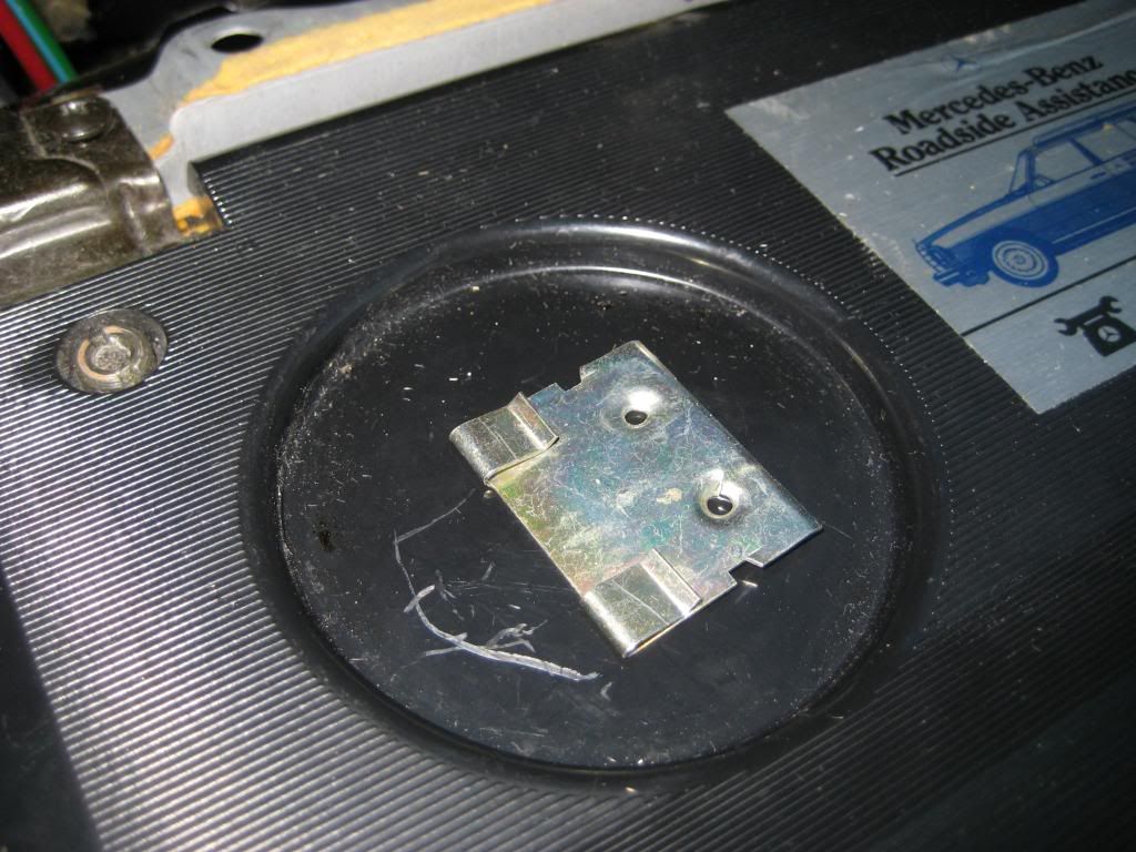 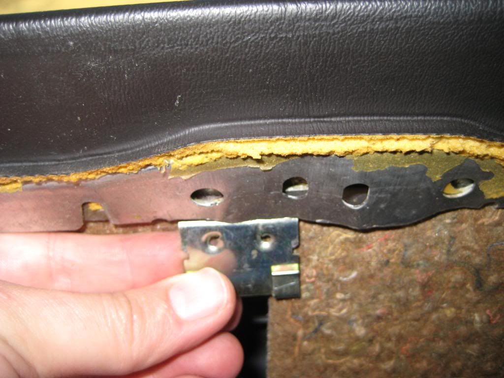 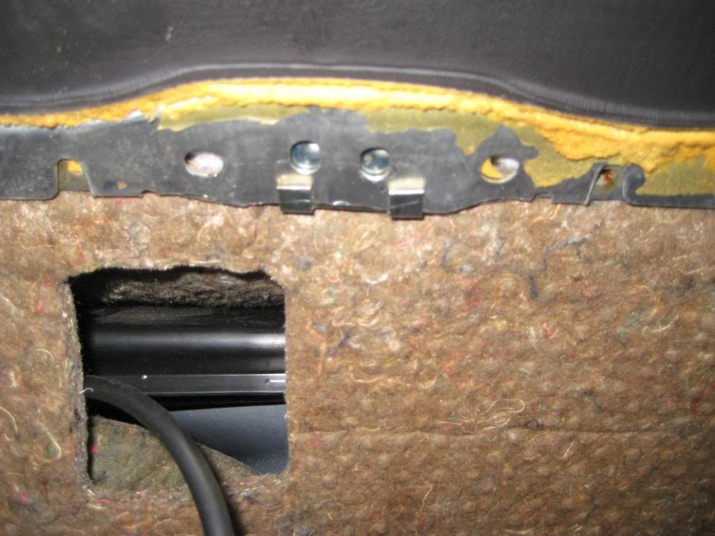 7) I released the electrical connector of the glovebox light fixture and removed the light fixture from the glovebox liner. You only have to do one when removing the glovebox liner - you can release the electrical connector as you pull out the glovebox liner, or release the light fixture from the glovebox liner and leave it attached to the dash harness. The first picture shows the electrical connector fished through the light fixture opening. The second picture shows the light fixture attached to the connector. The second through fifth pictures show the light fixture going into place - 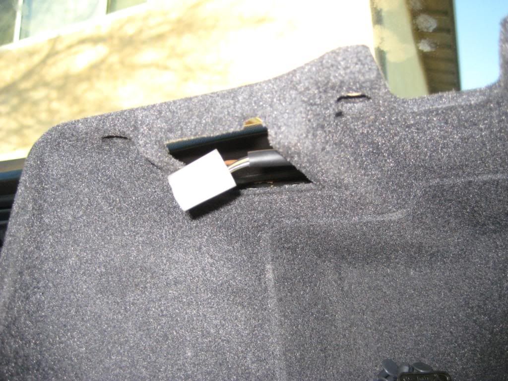 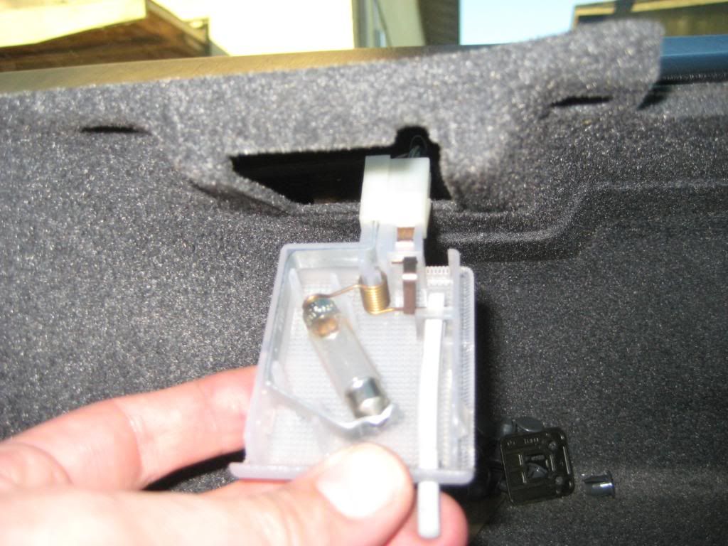 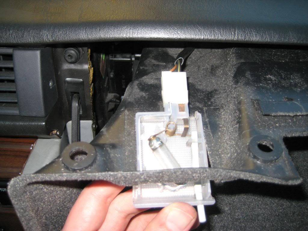 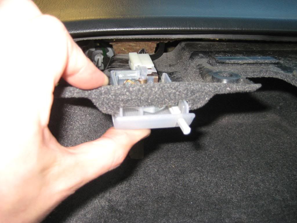 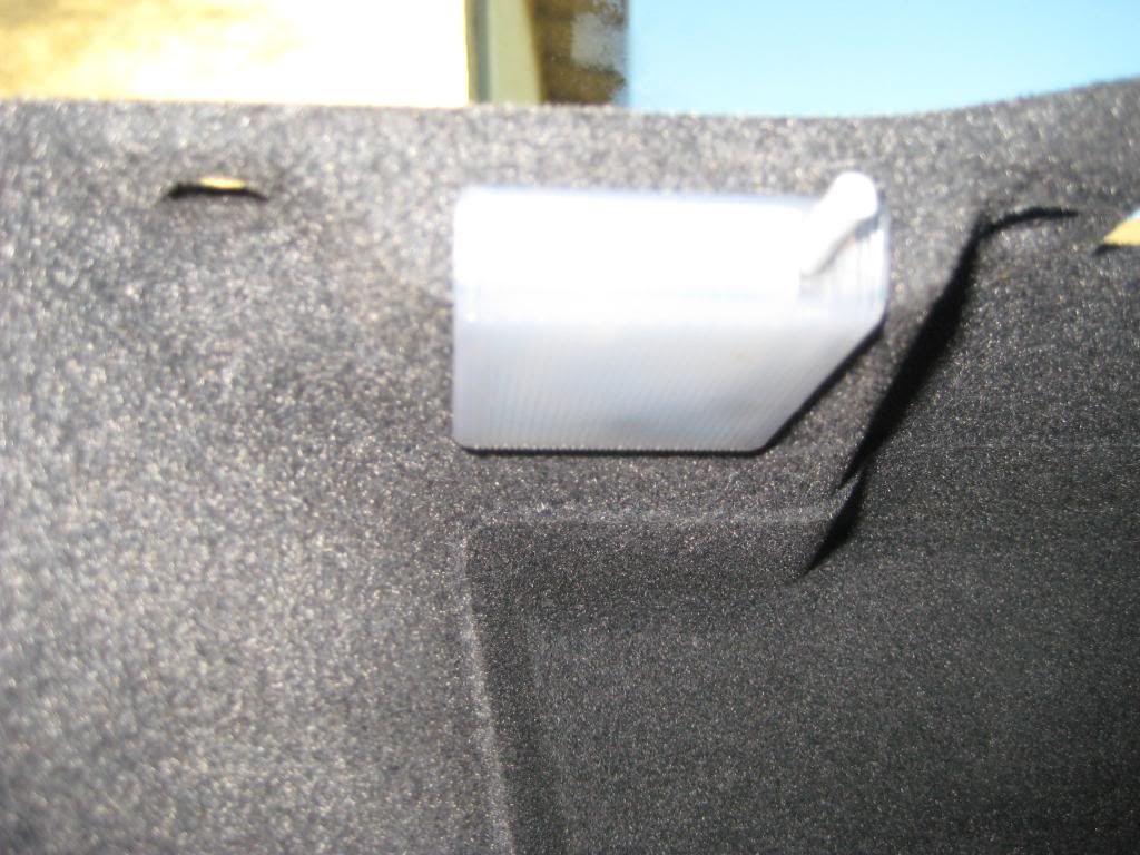 8) The glovebox liner is ready to go into place. Before that, do what you can to get the lower panel padding and upper dash padding back the way it was. I winged it since I didn't note how things were as the dash came off. I set everything neatly with no bunching or strange angles. The glovebox liner is held to the dash by 7 expanding plugs. There are 3 along the bottom and 4 along the top. The first picture shows the glovebox liner just about in place. Press it evenly until the opening edges snap into place. The second picture shows where the glovebox door striker attaches. The third picture shows the glove box door striker held by a single proper black Philips head screw and a makeshift second screw (it would be days before I find the second screw). The fourth picture shows 1 of 7 expanding plugs that hold the glovebox liner to the dash. The fifth picture shows the plug pressed into place. The sixth through eighth pictures show the pin going into the plug. The ninth through eleventh pictures show the expanding plugs and pins in place. The twelfth picture shows the striker in place after adjusting the glovebox door (yes, a screw is still missing) - 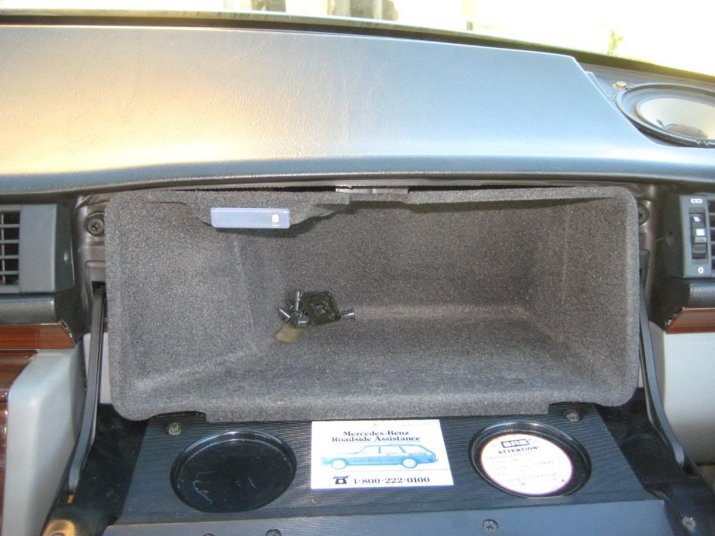 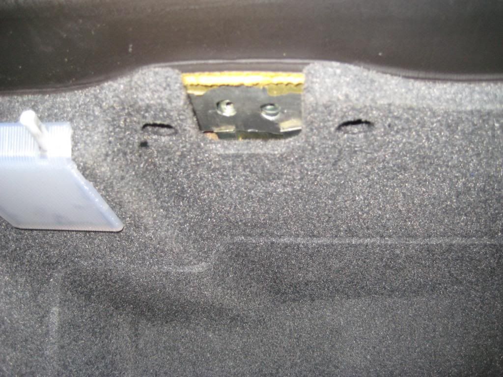 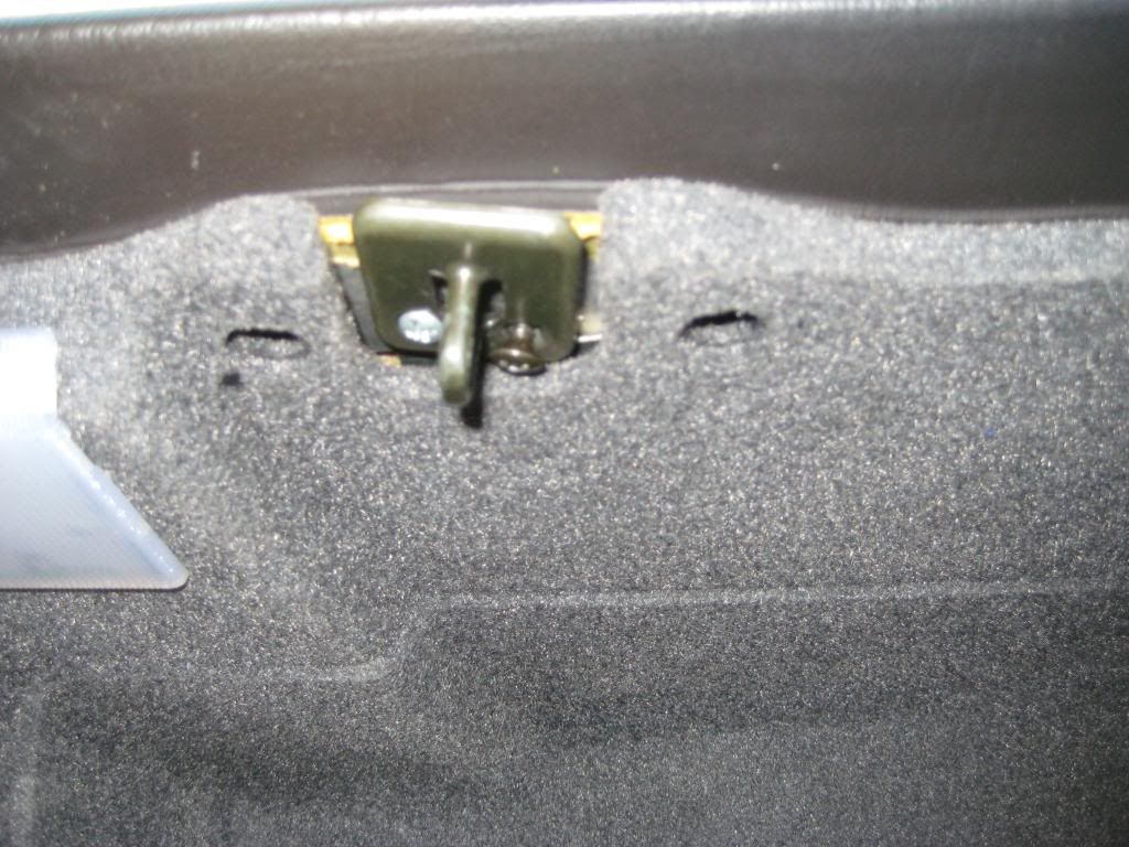 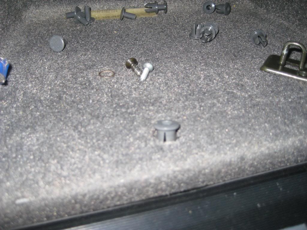 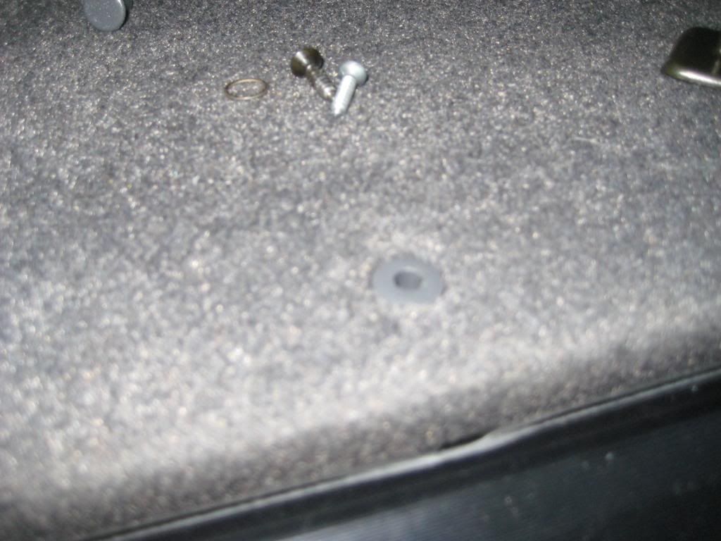 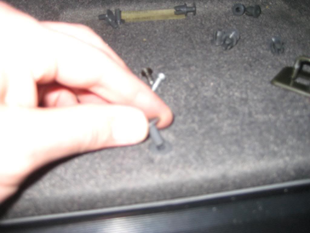 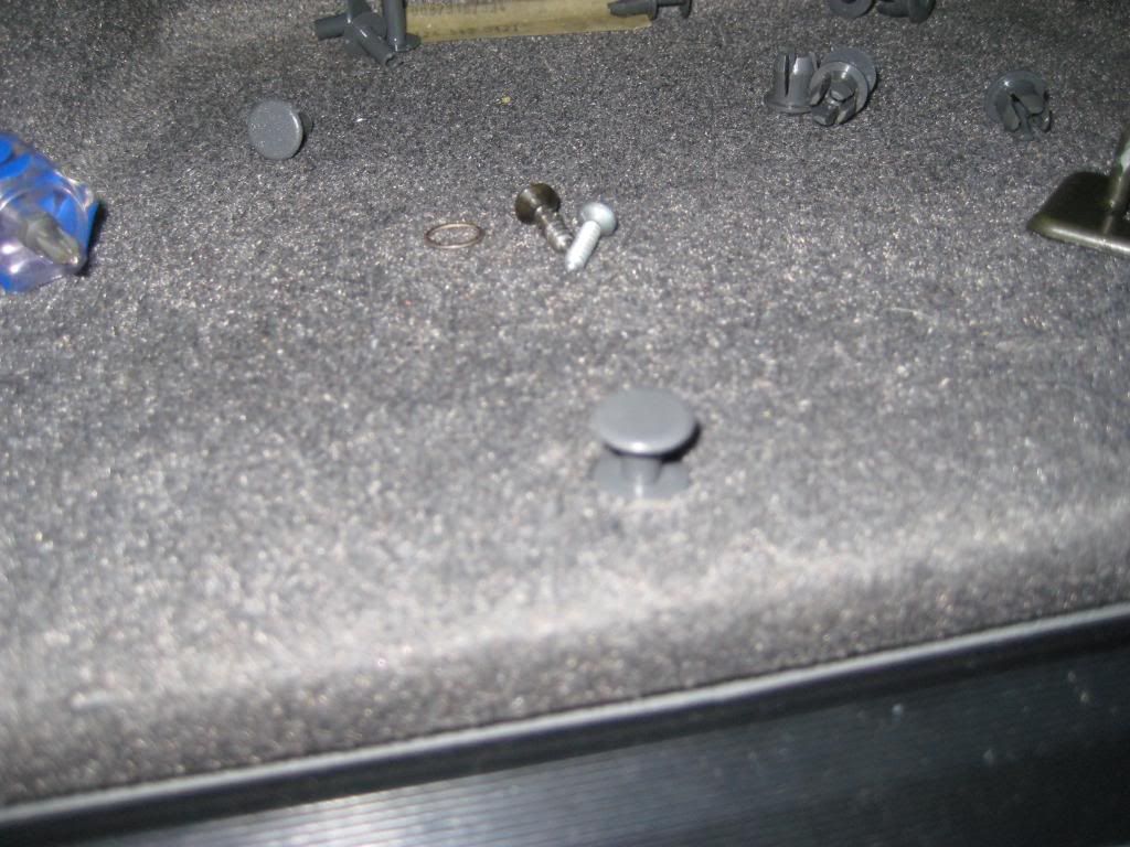 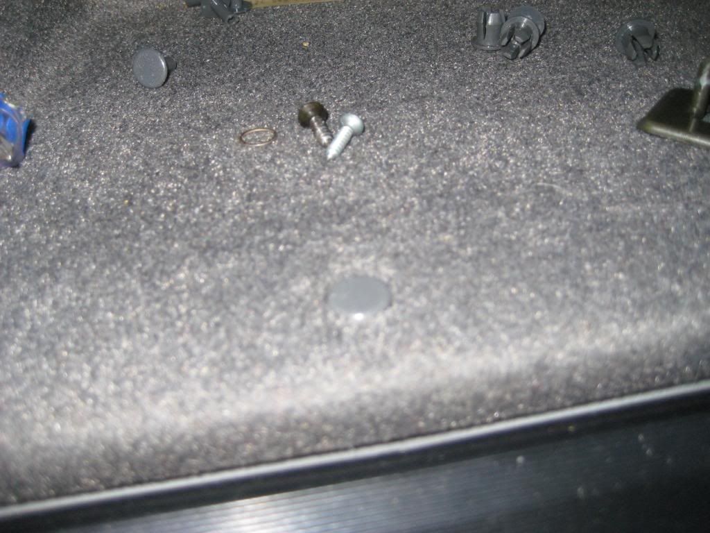 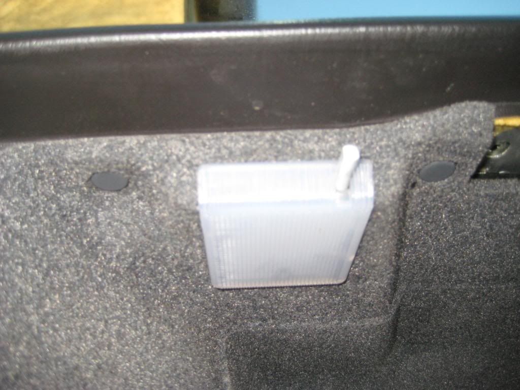 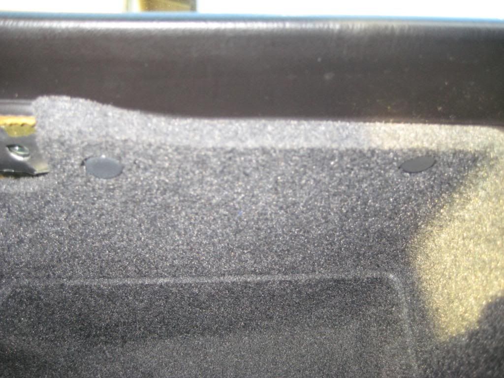 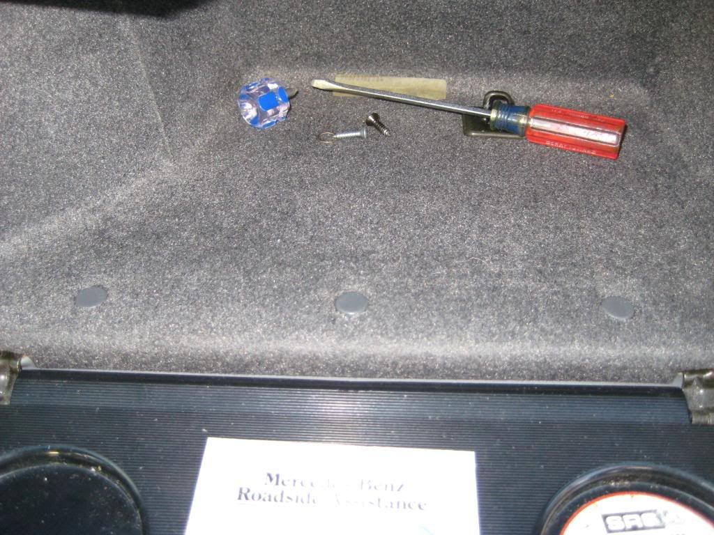 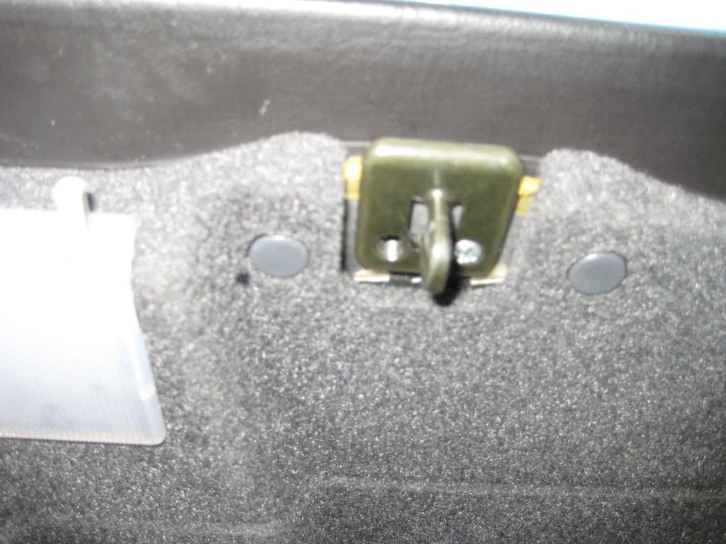 Sixto 87 300D Last edited by sixto; 03-10-2009 at 03:44 AM.
|
|
#6
03-10-2009, 02:58 AM
|
||||
|
||||
|
9) Looks done, doesn't it? If you attached a different glovebox door as I did, you'll have to transfer your original glovebox latch and lock so the lock matches your key. Set both latches to the unlock position so the latch you're keeping goes into place the way it should. I had to futz with the key a couple of times with the latch out but on the third try the latch worked properly.
The first picture shows the glovebox door open and a preview of what I keep in the glovebox. The second picture shows the latch and lock coming off and which 3 Philips head screws to remove to release the latch from the glovebox door. Note the 4 cog pinion on the locking mechanism that engages the rack. What rack? Why the rack in the third picture. This is a fully exposed rack because the glovebox door in this picture is fully apart. With only the latch removed, only about the left quarter of the rack is visible. The fourth picture shows the glovebox door fully in place (yes, I will go back and fit a glovebox door with wood) - 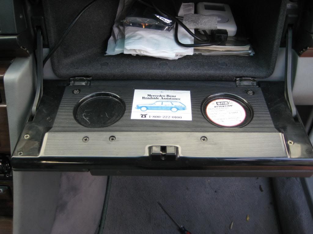 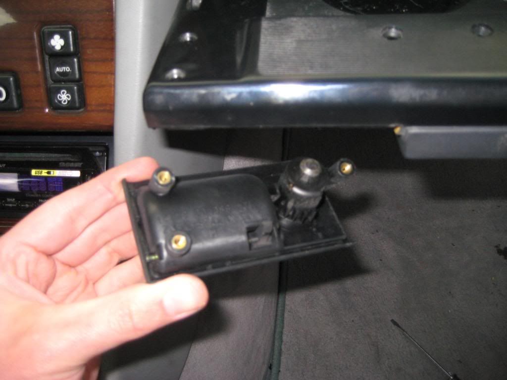 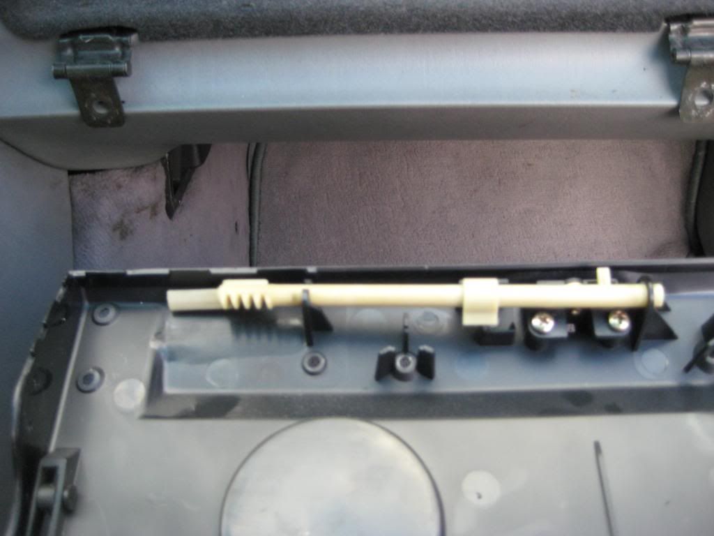 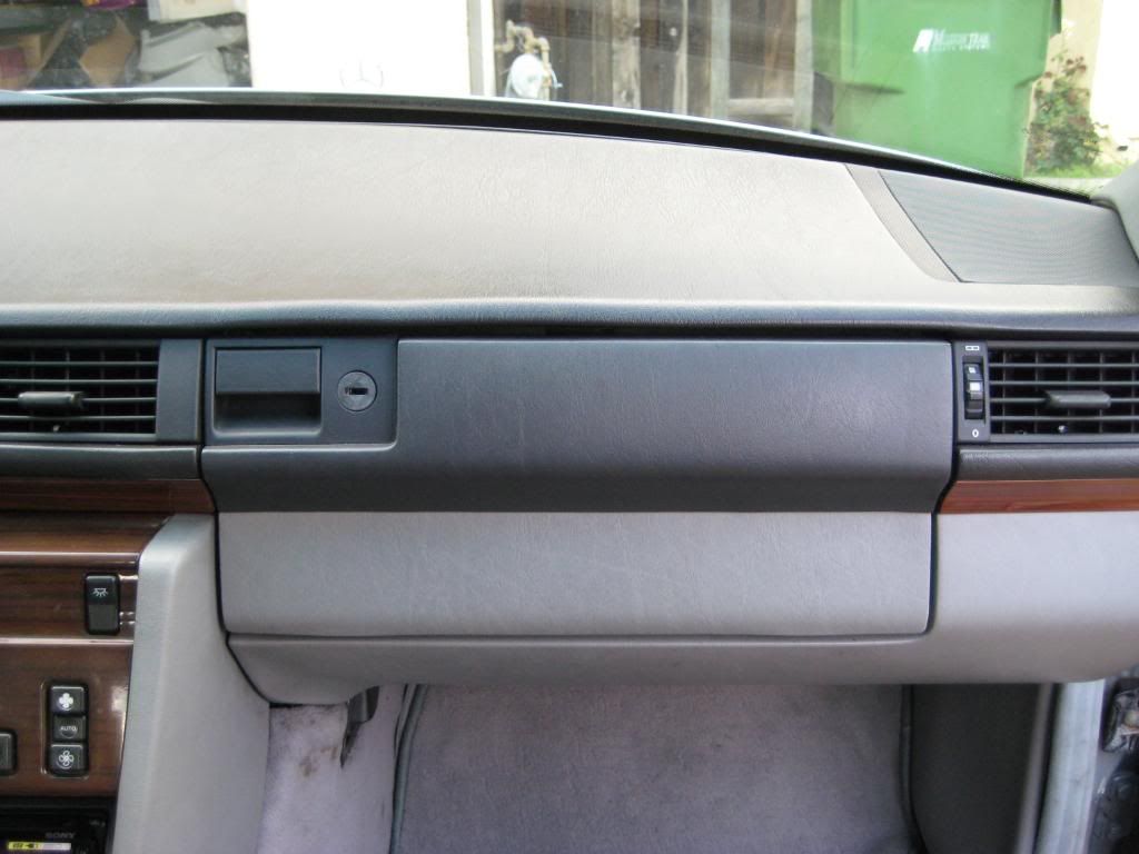 Actually I transferred more than just latch since I wanted to keep the original airbag date reminder. I can walk you through taking the glovebox door apart. Just ask. Sixto 87 300D Last edited by sixto; 03-10-2009 at 03:46 AM.
|
|
#7
03-10-2009, 02:58 AM
|
||||
|
||||
|
Now to finish the topside trim. I describe the passenger side of each step. The driver side is the same.
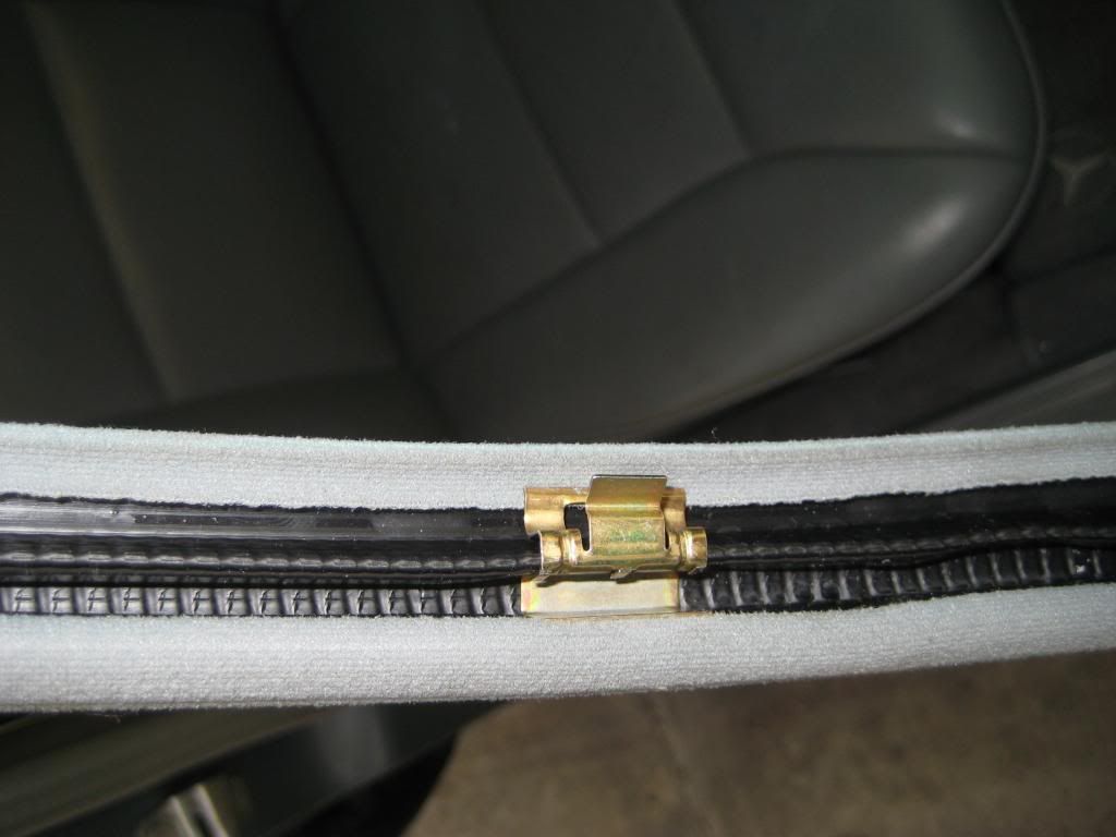
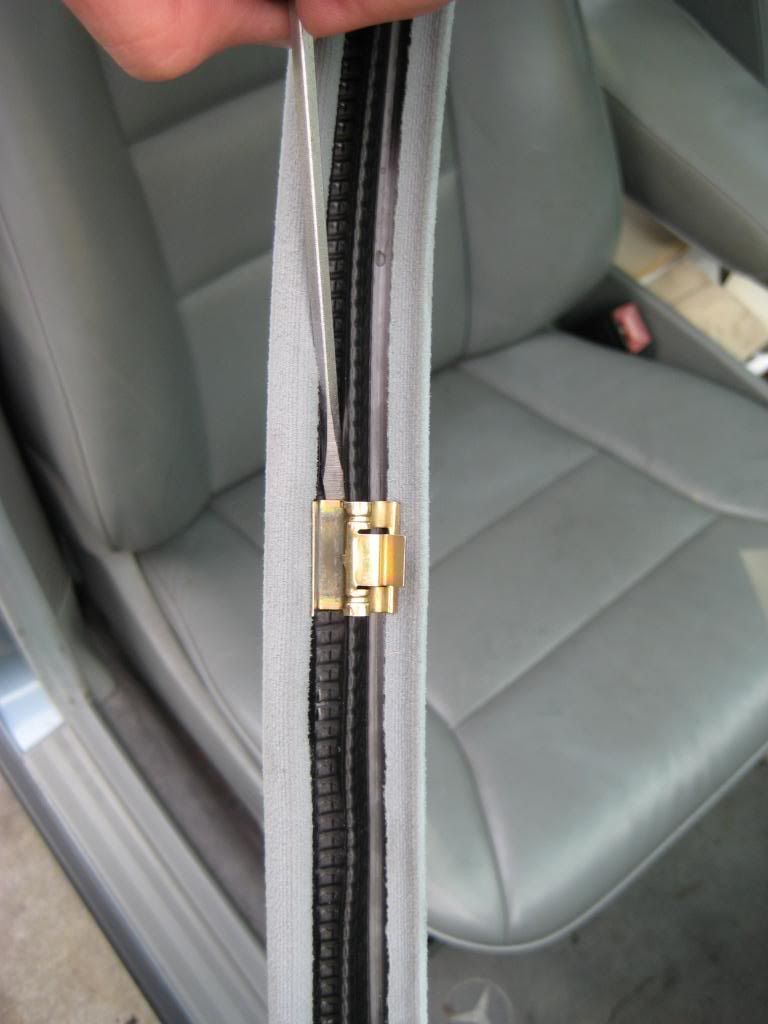
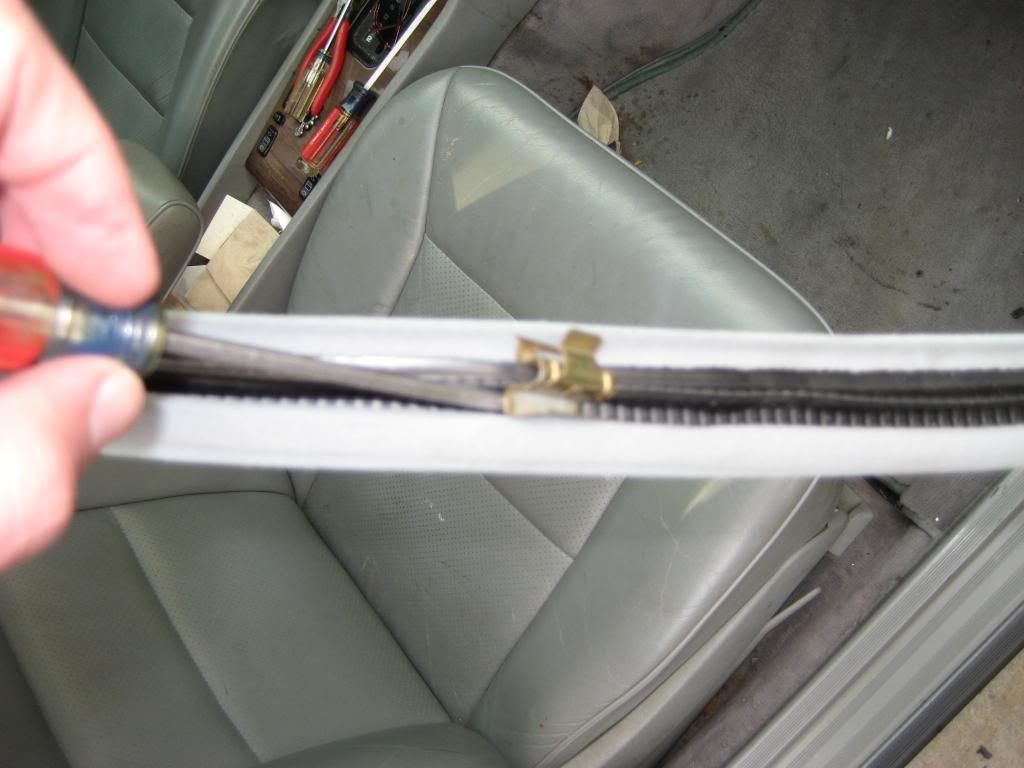
1) I've removed and installed the speaker grills with the A-pillar trim pieces in place. It's easier to do with the A-pillar trim pieces off so I installed the speaker grills first. The speaker grills have hinge tabs that engage slots in the outer edges of the dash. Engage the hinge clips in the slots in the dash then set the inside edge of the speaker grill onto the dash. There is a long Philips head screw that goes diagonally towards the windshield and one that goes downward into the trailing edge of the dash. The cover trim piece goes on only one way. One end has a horizontal tab that slots into the windshield edge of the grill . Starting at the windshield edge, work towards the trailing edge pressing the trim piece into place every inch or so until the trim piece is fully set into place - 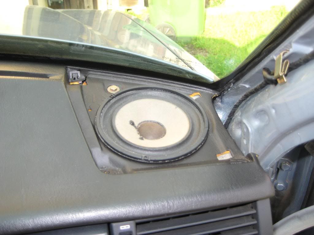 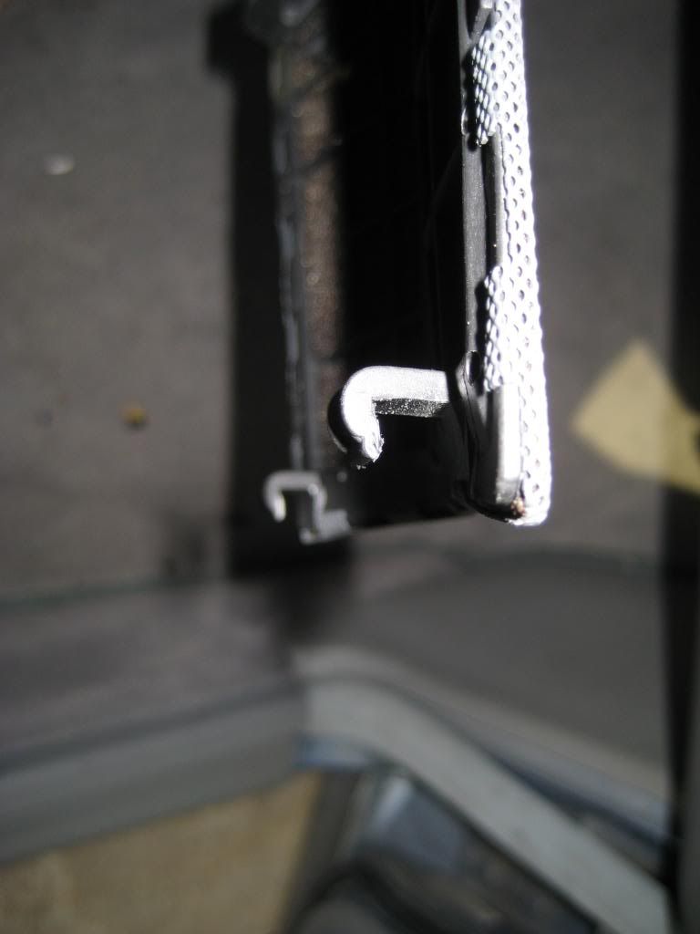 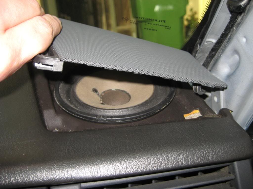 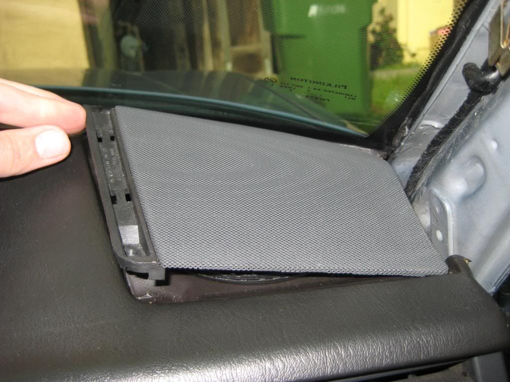 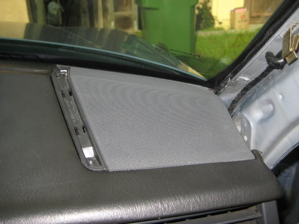 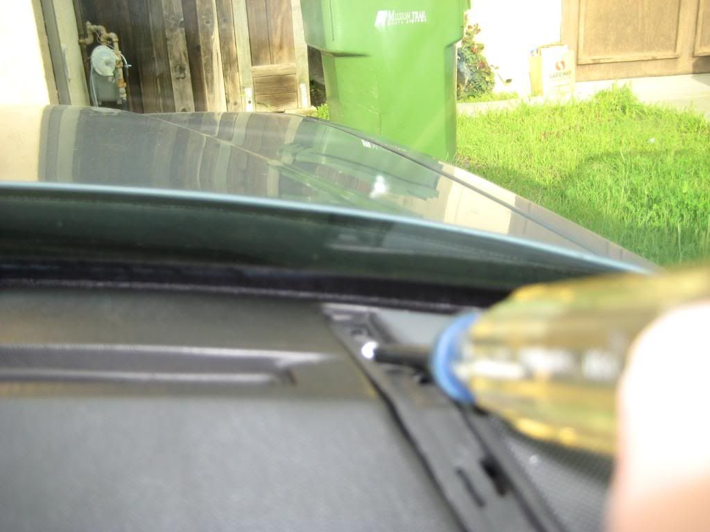 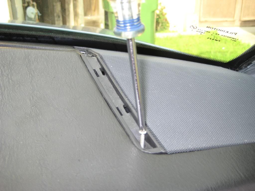 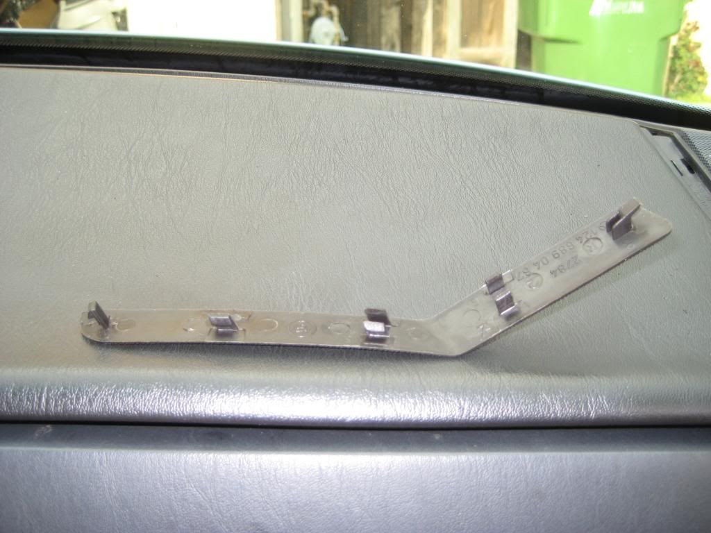 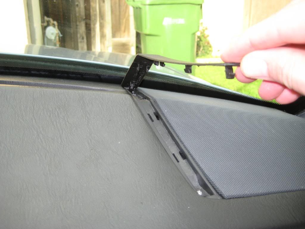 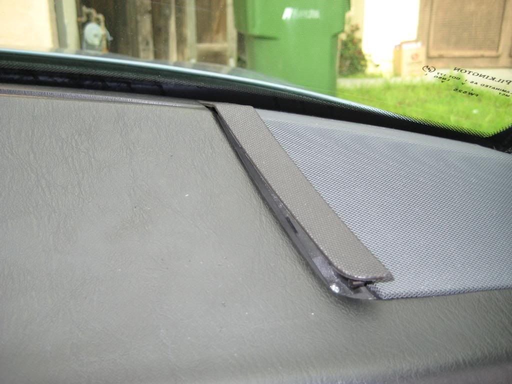 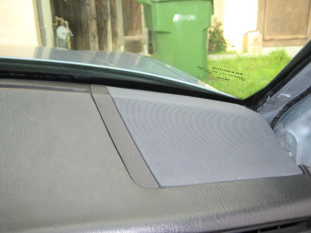 2) The clips that hold the A-pillar trim to the A-pillar tend to stay on the A-pillar. I had no luck getting the A-pillar trim pieces to slot into the clips so I removed the clips and fit them first to the A-pillar trim pieces. It takes a lot of prying to get them out. Keep the doors and windows closed and wear eye protection. Also watch how you're prying so if the tool slips it doesn't damage the windshield. The clip is gnarly. If they made fish hooks like this there wouldn't be stories of the one that got away. It certainly wouldn't get away with its mouth intact. I pried the top edge then the bottom edge then the top edge then the bottom edge to rock the clips off the A-pillar. Note how the clips are set in the A-pillar so you know how the attach to the A-pillar trim pieces. Set the clips in the slots in the A-pillar trim piece. Engage the trim piece in the headliner. It goes between the upholstered headliner trim and the gold colored metal piece. Swing the lower end of the trim piece over the speaker grill and just about into place. Peek between the pillar and trim piece to align the clips with the pockets they attach to. Press the trim piece right where the clips are to get it into place. 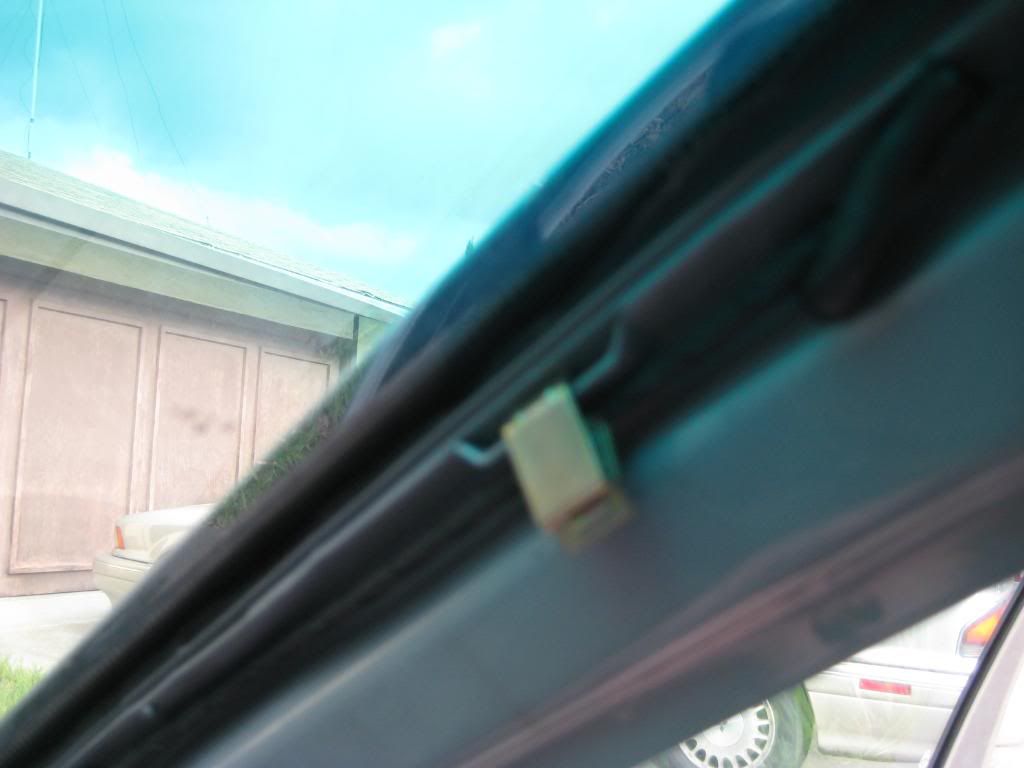 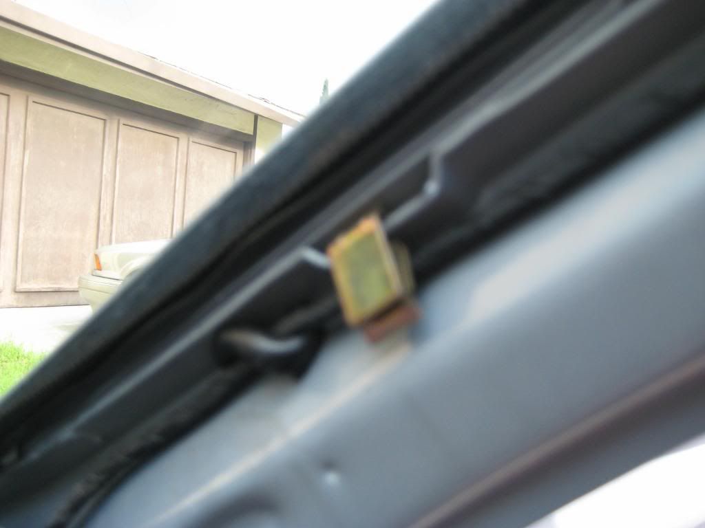 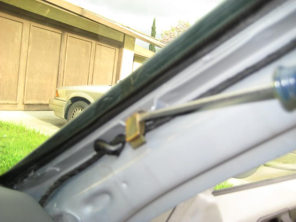 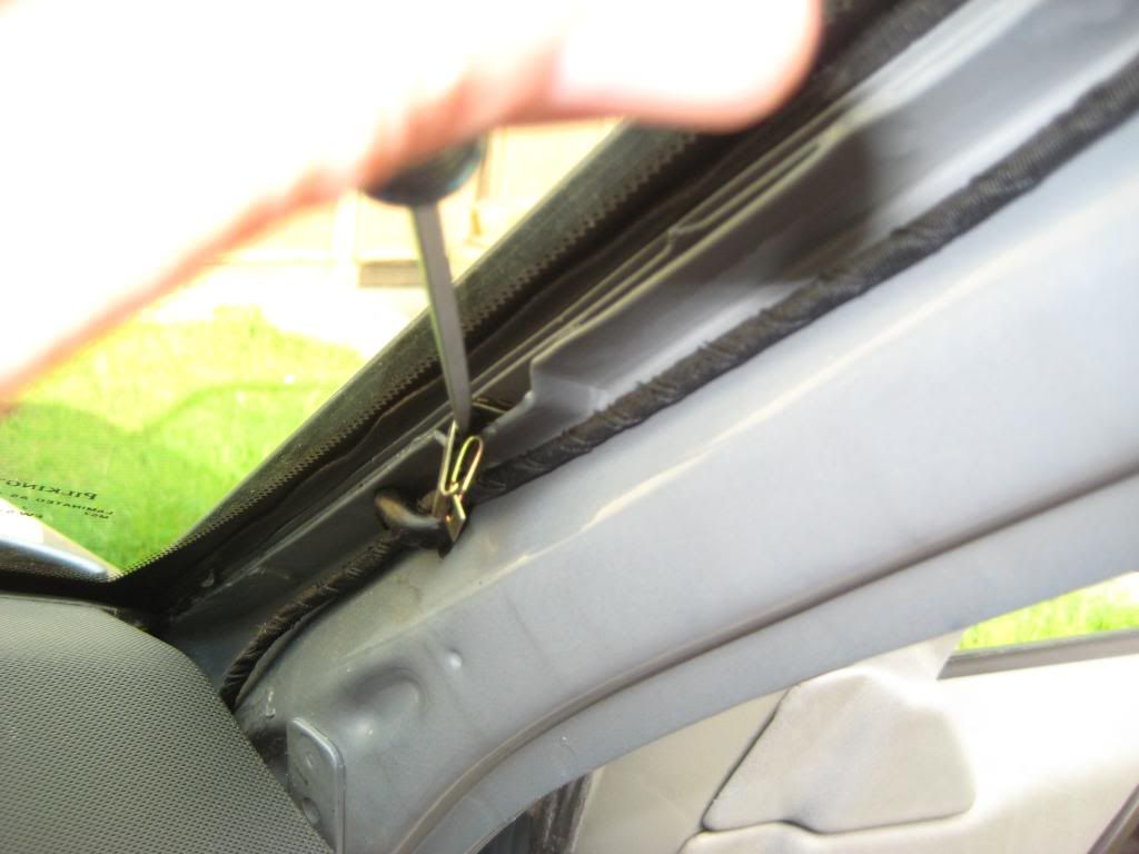 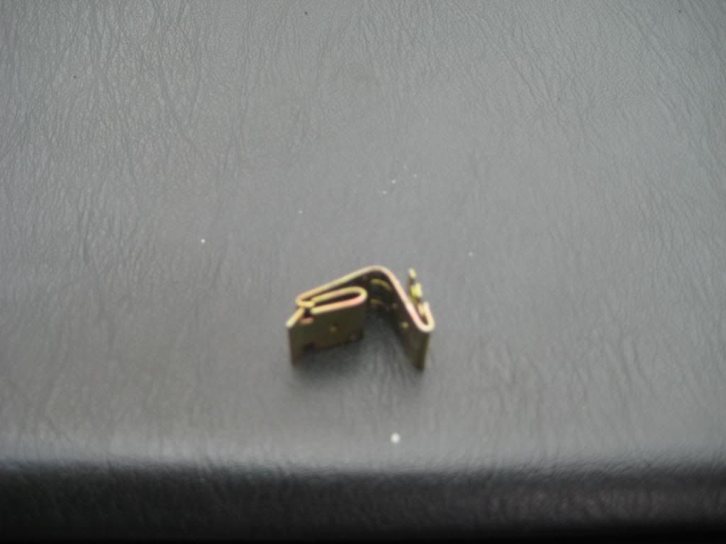 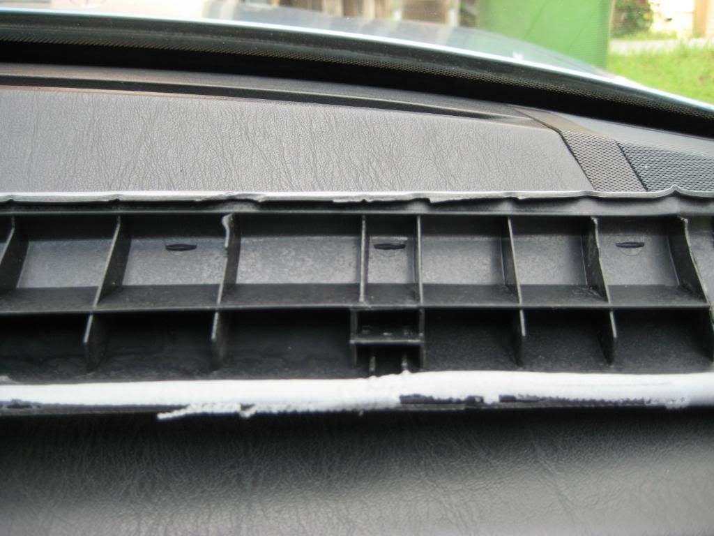 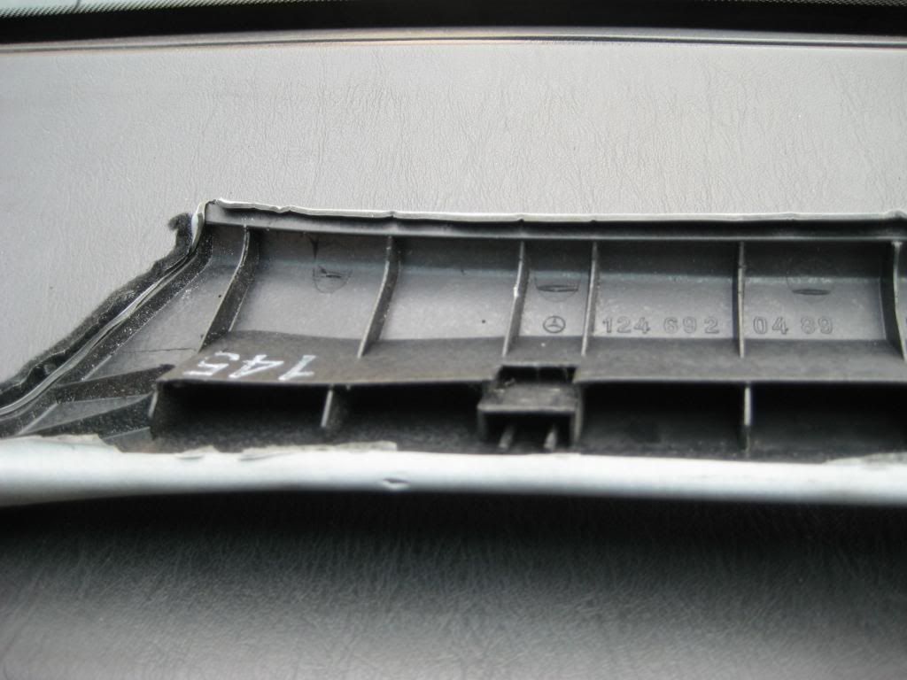 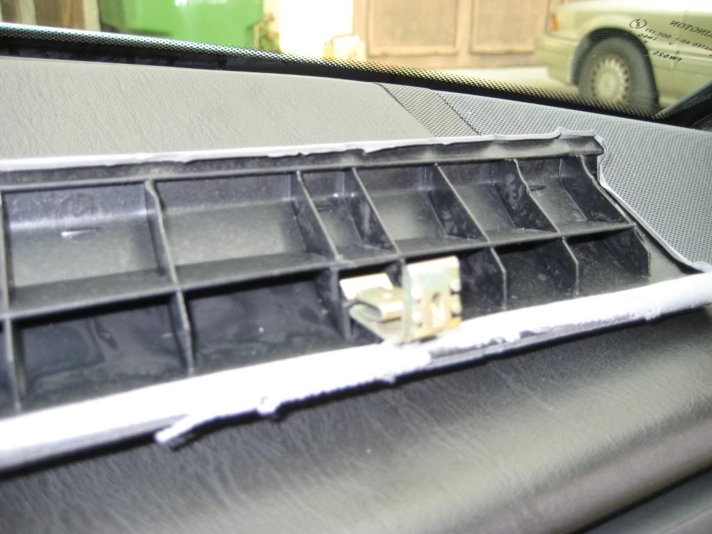 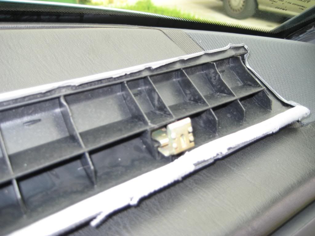 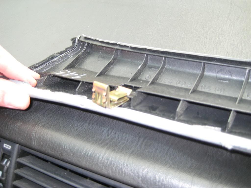 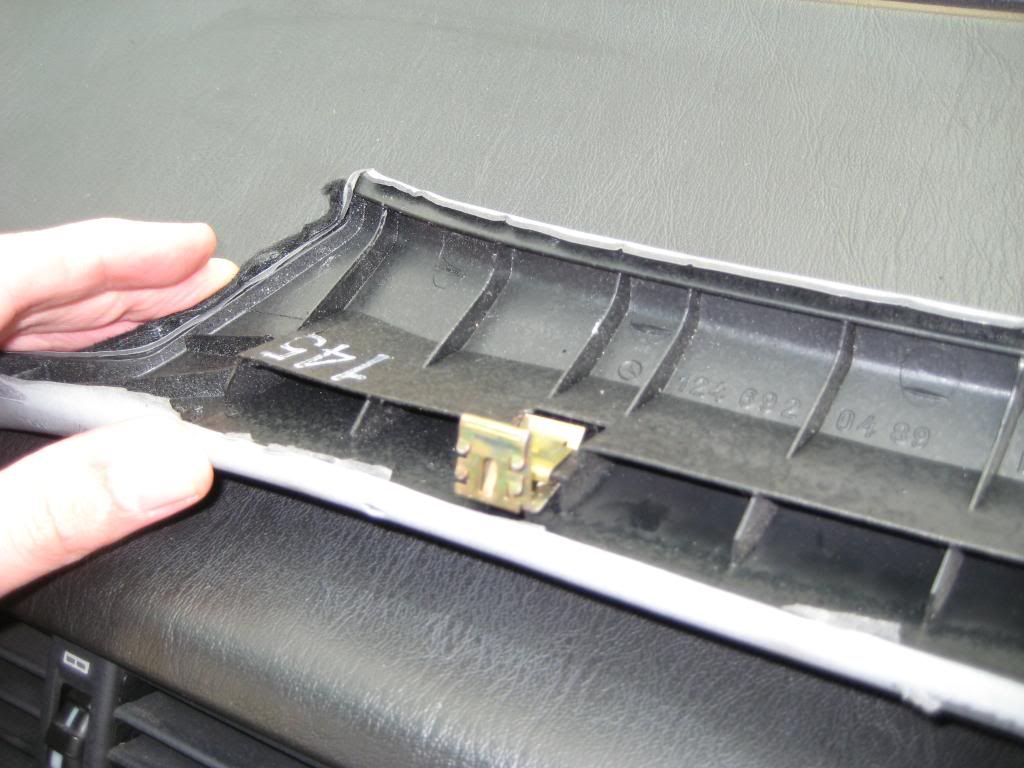 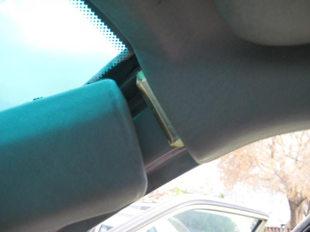 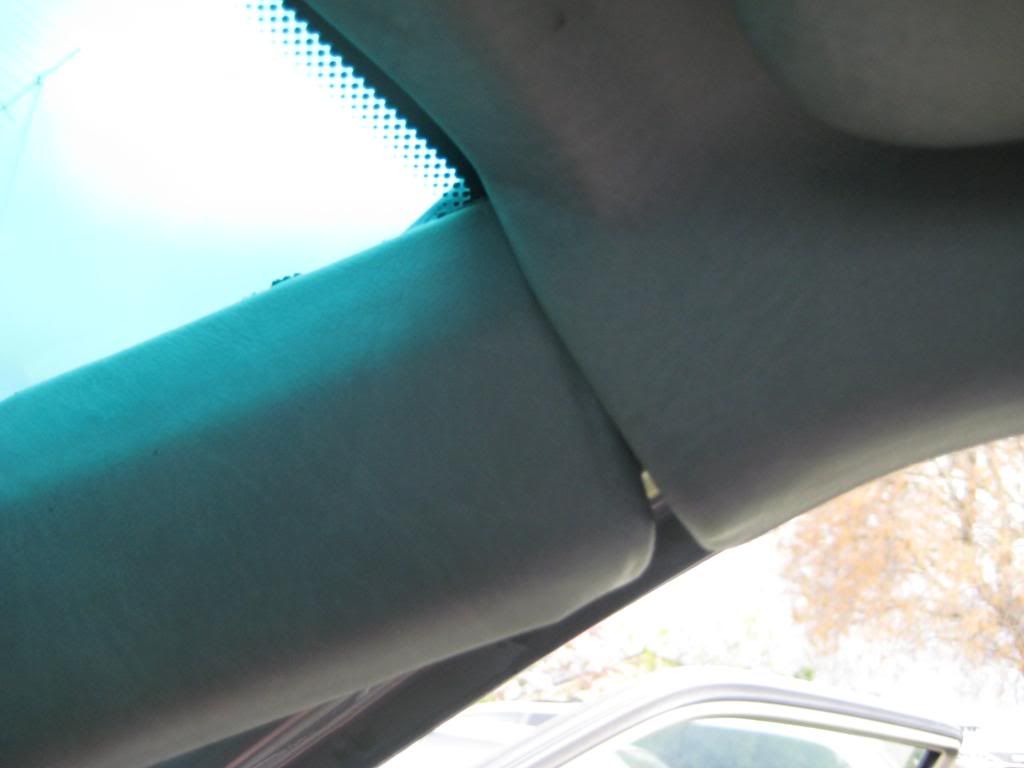 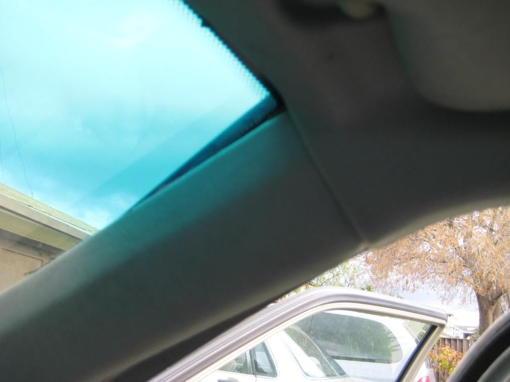 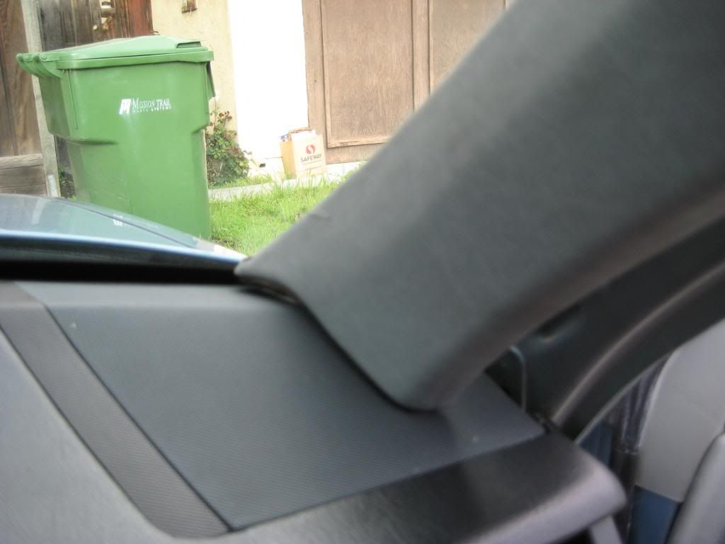  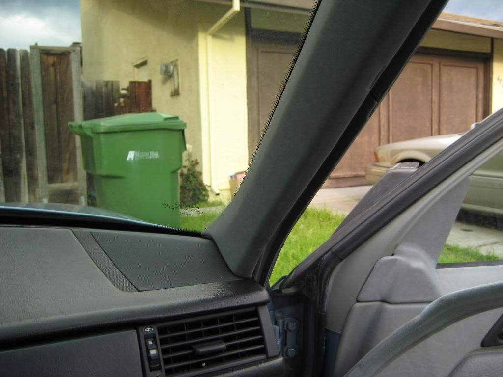 Sixto 87 300D Last edited by sixto; 03-10-2009 at 03:48 AM.
|
|
#8
03-10-2009, 02:59 AM
|
||||
|
||||
|
3) There's a gold colored clip along the windlace that holds the A-pillar trim piece in place about halfway up. I pried the clip off the windlace to determine how it engages the trim piece. The small tab tucks between the trim piece and pillar and the wide tab goes over the trim piece. My trim pieces had a mark indicating where the clip's wide tab made contact. I set the clip in the pillar then pressed the windlace into place -
        Sixto 87 300D
|
 |
| Bookmarks |
|
|


 Linear Mode


