

|
|
|
|
|
|
#31
 05-26-2014, 03:57 PM
|
||||
|
||||
|
Hi John,
The job is pretty straight forward. The 2 lines that are coming out of the back are the 2 you want to take off (smaller ones). The large ends closest to the valve are tightened into the body of the valve. The smaller male ends are the ones that you want to loosen that go into the larger. The larger ones won't turn, but allow you to get leverage if needed. The catch is that if there is any pressure in the lines, it will be released when you loosen those nuts holding the metal lines in place. So, have a large container, or oil drain pan, handy or you will be cleaning the fluid off the garage floor. If the car is on ramps or the ground, it will level all the way down, so make sure you have clearance and it doesn't come down on you!!! If it is on a lift or jack stands, then it won't get any lower as the weight is not on the suspension and the fluid loss will be minimal. I did not use any PB, I just grabbed a wrench and cracked them loose. I did not run into any problems with that, but I may have been lucky, but nonetheless they came loose with normal pressure for something that has been under a car for 30 years. After that I removed the adjustment arm and then the 2 bolts/nuts that secured the valve to the bracket and it was in hand at that point. The other two bolts/nut hold the halves together and can be removed on the bench. I hope that helps. You came to the right place for questions, ask as many as you have before tackling the job if this isn't something you are accustom to. If you are mechanically minded as a whole, this is not a tough job.
__________________
1980 300TD, SOLD 1984 300TD, 275K  1999 C230 K Black & Tan 2013 C250 Black 1974 CJ5 Red You might faint from the fight, but you're gonna find it. Every challenge could have paradise behind it. -John Popper- 
|
|
#32
05-26-2014, 05:34 PM
|
|||
|
|||
|
Thanks FirstDiesel.
Its on ramps right now but I will put some jacks underneath to be safe. To confirm, is it counterclockwise to loosen all the lines? If they are stuck, don't want to go the wrong way and make it worse. Thanks. -John
|
|
#33
05-26-2014, 07:49 PM
|
|||
|
|||
|
Yes, ccw...
Definitely set the car frame on jack stands!!! Make sure it's high enough you can get out from under it easily. Just sayin'...
and Yes, turn the fittings counter clockwise to loosen. Clockwise to tighten. Quote:
__________________
Dedicated to the preservation of antique Mercedes Benz's, one rusty ol' bucket of bolts at a time!
|
|
#34
05-27-2014, 11:13 AM
|
||||
|
||||
|
Quote:
Agreed, no reverse threading on any of this project. Remember, this is one of those "the car can crush you" projects. Be safe.
__________________
1980 300TD, SOLD 1984 300TD, 275K 1999 C230 K Black & Tan 2013 C250 Black 1974 CJ5 Red You might faint from the fight, but you're gonna find it. Every challenge could have paradise behind it. -John Popper-
|
|
#36
05-28-2014, 03:17 PM
|
|||
|
|||
|
Quote:
|
|
#37
05-29-2014, 04:19 PM
|
|||
|
|||
|
I know I'm slow at this, I got the valve off after about two hours. Two things I am thinking about whether or not it would help, but it may be a good idea to loosen the 10mm nut first, as well as starting to loosen the other two bolts that hold the two valve halves together.
My reason for this is that I took off the lines, and then the two bolts holding the valves in place, and then had a tough time taking off the 10mm nut since the valve would move freely when trying to do so. And currently I have the valve free, and since I don't have a vise to hold it in place, having a helluva time loosening the two bolts that hold the valve together. Sorry, this is from the noob perspective, not sure if there are other tricks to do. -John
|
|
#38
05-29-2014, 10:30 PM
|
||||
|
||||
|
Here's another trick.
In my case, I could remove the hydraulic lines without a problem, but it was getting the bolts holding the valve to the bracket that wouldn't budge. You can go straight up into the bracket and undo 4 screws/bolts to remove the valve and bracket. You just need a socket extension or two.
__________________
85' 300D No inspection, No registration fees, Cheap insurance  "If my calculations are correct, when this baby hits 88 miles per hour, you're going to see some serious %$&^."
|
|
#39
05-30-2014, 01:36 AM
|
|||
|
|||
|
Ok.. so I think I am very close to being done. Here's some pics I took.
I wanted to shoot this picture to see if you guys could confirm that everything is in the correct position as in the black and white picture in post #2 showing the position of the cam during the reinstall process. 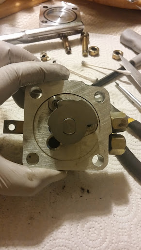 One of my big oops was not indexing the rod and the lever arm. Correct me if I am wrong, but in the picture above, I should be ok if lever is in the 9 o clock position, the notch on the other side is in the 3 o clock position? The below is just showing the notch in the rod is 180 degrees from the long end of the lever.  A couple of questions I had. 1) I'm not sure exactly what the locking rod that came with the kit does. Is it to be used during the reinstall process to just keep the lever from moving? And is to be used as in this picture?  2) I didn't get a clear look of inside the chamber in the valve where the piston goes into, but does it matter which side the large ball is on when reinstalling the piston back in? I didn't know if once you put the piston back in, whether or not the spring kept the large ball only on one side or not. And if so, which position the ball should be in. Thanks, John
|
|
#40
05-30-2014, 08:24 PM
|
||||
|
||||
|
The ball needs to be on the bottom, in the smaller part of the chamber, which is where I think I might have messed up mine. An easy fix now that I've taken this all apart once, but I am on the bottom of the dipstick on fluid. Fluid is on the way and I want to try that first before the reassembly. I think I did it right with the ball, but I'm 60/40 sure.
Edit: Oh, and your first picture above looks exactly how I did mine, for what that's worth.
__________________
85' 300D No inspection, No registration fees, Cheap insurance "If my calculations are correct, when this baby hits 88 miles per hour, you're going to see some serious %$&^."
|
|
#42
06-01-2014, 12:50 AM
|
|||
|
|||
|
I'm going to assume its to the center since Andrew's black and white pic here looks that way.
 I think I am on the home stretch. Got everything except for the top two accumulator lines. For the life of me, they will not go in. I try to start them by hand until I feel a little resistence and then I try to slightly pull the line out to see if it actually caught any threads but the line pops back out every time. Renntag mentioned to try to start all the lines before bolting the valve in place. I tried that route but I do not see how that is possible for the accumulator lines, it would only work for the supply and return lines. The reason being is that the upper left bolt is underneath the accumulator lines. I spent over an hour trying to get the lines in but no luck and it got dark. I knew it was time to call it a day when I saw a black widow in the undercarriage.
|
|
#43
06-02-2014, 07:18 AM
|
||||
|
||||
|
Yes on the large ball position placement.
My fluid arrived. I need to remove the valve and check the position of the ball. 
__________________
85' 300D No inspection, No registration fees, Cheap insurance "If my calculations are correct, when this baby hits 88 miles per hour, you're going to see some serious %$&^."
|
|
#44
06-02-2014, 09:42 AM
|
|||
|
|||
|
Quote:
|
|
#45
09-16-2014, 10:24 PM
|
||||
|
||||
|
I sent the OP a message about buying a kit, but I haven't heard anything in a few days... Just a pestering bump.
|
 |
| Bookmarks |
|
|


 Linear Mode


