

|
|
|
|
|
|
#1
 08-07-2011, 09:37 AM
|
|||
|
|||
|
Megasquirt on my M110
Finally found the time to buckle down and get to work on the M110.
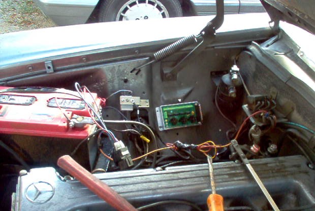 Decided on mounting the relay box on the right fenderwell. I didn't care for this spot because the exhaust is on this side. There isn't enough room on the firewall, mounting it in my preferred location (left front fenderwell) is counter productive due to the length of the controller cable required.  A better view without all the wiring mess in the way. Mounting it this close to the shock tower has it's drawbacks but the pluses out weigh them. The front two holes have to be drilled through a doubled metal area. A fact I discovered at the cost of an expensive drill bit. It has to mounted far enough forward to allow access to the DB37 connection with a screwdriver to tighten the locking screws. A fact which was discovered the hard way as once the cable is in place you can't access the rear hold down bolts to tighten them.  This also worked out well on my '74 as it gave me easy access to the needed power. The sensors will also be on this side (coolant, O2 and intake temp) so it shortened up my wiring runs. This also worked out well on my '74 as it gave me easy access to the needed power. The sensors will also be on this side (coolant, O2 and intake temp) so it shortened up my wiring runs.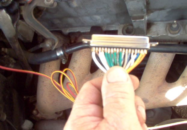 I would suggest BUYING the relay cable pre-made. Unless you are adept at fine wire soldering and have a solder pencil it is a real pain. You need to remove one of the DB37 housings to feed it through the hole in the firewall. The image is purposely fuzzy to not show my nasty-arsed soldering job.  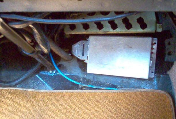 Where the controller unit is located. It will be hidden by the under dash knee cover. When you mount it take care to leave enough room for cable access to BOTH ends of the unit. The DB37 will be attached on the side closest to the hole in the firewall and the DB9 tuning cable has to have enough room for easy connections. Oh yes, once again, the box needs to be mounted BEFORE you install the DB37 cable. Frick! 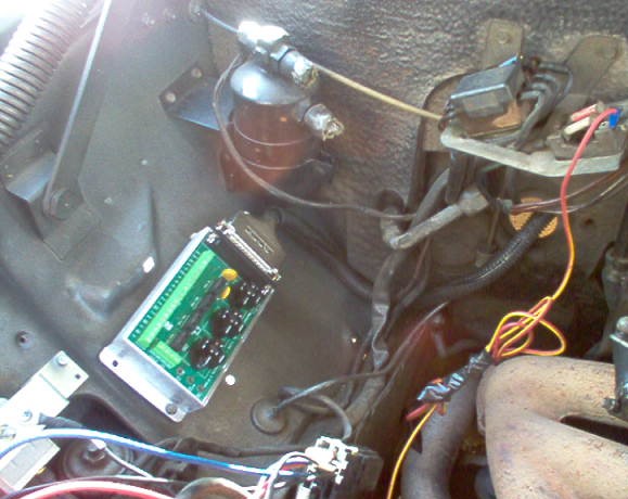 Rough mounted showing the cable running through the firewall. It was at THIS point I discovered the whole screwdriver/mounting problem. 
|
|
#2
08-07-2011, 10:10 AM
|
|||
|
|||
|
Final mount of the relay box with some wires I attached for testing the unit's operation. Just a couple of sensor wires and tach input which will not be in the haphazard way they are now.
I picked up the power at the terminal strip already mounted on the firewall. Both 12V battery and 12V ignition which made my wiring run short and fairly neat. You can't see it in this picture but the ground for the board is routed to main engine ground strap.  It's alive! The reason for my sloppy sensor wiring. I wanted to get the electrical connections verified before I went further. Nothing like an overlooked connection problem to really frustrate you later on down the process. The injector pulse reading is in the red because there are no injectors installed for the ECU to get feed back. 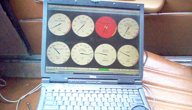 The wiring is good and we have power so it's time to move on to the next phase. The TBI unit. I get to cheat because I just happen to have an M110 engine sitting on a cart in my work shop. Carb, linkage, most hoses and lines removed for ease of access and display purposes. You won't have to strip your car down this far.  The next two pics are of the Holley adapter plate (Holley part #17-41). I did have to re-cut the two rear mounting holes and using a dremel tool with a carbide bit recess a socket for the use of allen head cap screws to get the clearance I needed for the TBI. I'll show them in the next series of pictures.   I also drilled and helicoiled the three TBI mounting holes for metric threads. Not really needed but I figured I'd be consistent instead of using a mix of standard and metric bolts.
|
|
#3
08-07-2011, 10:59 AM
|
|||
|
|||
|
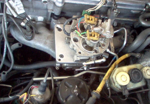
Time to begin fitting the TBI unit.
Used an old gasket to make the template for the adapter holes. 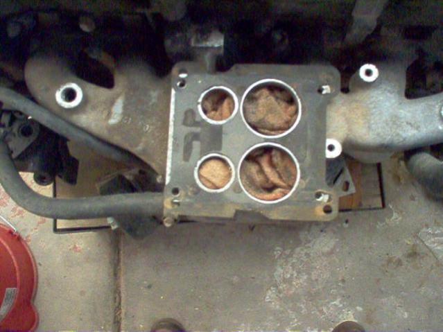 The next two are rough fitting the adapter. They are not the best of shots but you can see where I had to cut the recesses for the rear allen cap screws.   One thing which needs to be dealt with is the IAC on the GM TBI unit. It originally had a thick plastic "surround" into which the wiring plugs. That wasn't going to work as it hit the cam housing. Two ways to deal with it. Plug the hole and use a remote IAC or remove the surround and use some right angle connections. I went with the connectors. The surround is easy to remove as it is a brittle plastic. I gave it a quick buzz with a cutting wheel mounted in my dremel and it snapped right off.  Rough mounted showing the proximity of the IAC and the cam housing. It's not as close as it looks and once the connections are on there will be no interference. 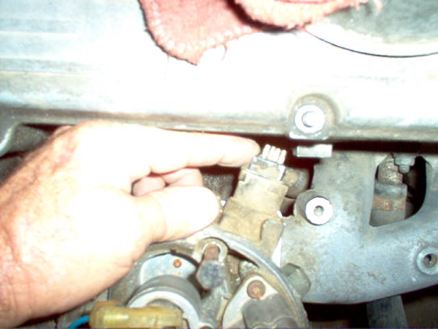
|
|
#4
08-07-2011, 11:30 PM
|
|||
|
|||
|
Here's how you take care of that pesky IAC problem. The pins are hollow so a quick bit of soldering, some heat shrink, and we're in business.
 Pre-wiring the TBI unit because it's a lot easier doing it on the bench than leaning over the car laying my forearm on that hot soldering iron I keep forgetting is right where I left it!  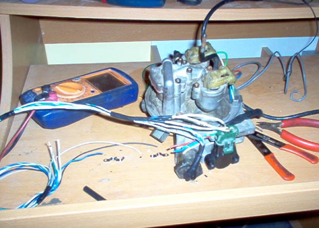 A view of how the IAC wiring looks when completed. Plenty of clearance!  A rough view of how the wiring will be run. It will be in a split loom and will run under the stock air cleaner. You'll only see it at the relay board connection. Neat, clean and out of the way. 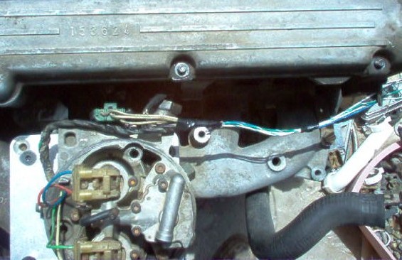 The air horn which goes on top. Same size as the original Solex's air aperture so the stock cleaner slips right on it. I might have to shorten the riser just a tad. Probably the thickness of the adapter plate. It's hard to tell with the loose engine. 
|
|
#5
08-08-2011, 12:36 AM
|
|||
|
|||
|
Nice work. I'm interested to see how the TBI setup works out. I would suggest building an aluminum heat shield between your relay board and exhaust manifold. Which version of MS are you using?
__________________
CENSORED due to not family friendly words 
|
|
#6
08-12-2011, 02:25 PM
|
|||
|
|||
|
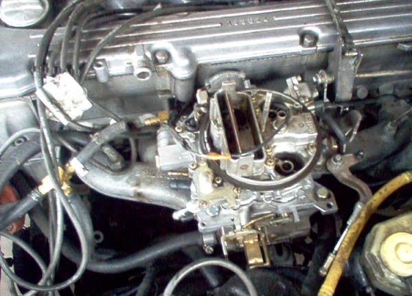
The old Holley carb set-up. Works fine but I want fuel injection with computer control and the ability to go to a complete managed system, fuel and ignition.
 One of the few modifications I had to make to the actual original set up. I had to grind 1/4" off these two throttle bracket mounting holes. It would be easy to undo this if I wanted to go back to a carb for any reason. Just a couple of flat washers and this never happened. I had to grind these to allow the throttle bracket to sit below the surface of the adapter plate. I could probably have removed the needed amount from the plate but this was much easier.  Rough fitting the TBI unit with the first version of linkage installed. I did have to remove most of the ridiculously cumbersome throttle bracket plate on the TBI unit itself and elongate the mounting hole for the linkage. Dremel tool to the rescue! Those are some standard cable ends available at just about any auto parts store with a short bit of all-thread.  Another alteration I had to make to the original set up. I drilled two 3/16" holes in the original feed arm and riveted an upright bracket piece. I didn't hurt the structural integrity of the arm and in fact the pivot ball for the original carb linkage is still in place. Simply drill out the two rivets, remove the bracket and you're back to stock. A small bit of the TBI external bracing rib needs to be ground away to allow the original feed to go all the way forward. You could probably get away with just adjusting the actual "throw" of the accelerator linkage (small rod mounted by the firewall) but I had the TBI unit off and it was one less thing to be changed on the original.  TBI unit mounted and the first fuel line in place (supply). It was a little tricky but using a coat hanger as a template I got it figured out. The first bend coming from the TBI unit is tough to do. It needs to go up just a bit to give adequate clearance for the linkage. I'd suggest using a spring style of tubing bender for this first bend and then using a standard bender for the rest. I'll be re-working this line because I am not 100% thrilled with the way it looks. Works fine but I want it to look a bit better. It's not too bad. $14 for the line. Could be worse, we wont mention the $50 IAC I screwed up. 
|
|
#7
08-12-2011, 04:29 PM
|
|||
|
|||
|
The return line formed and in place This is a lot more complicated than it really needs to be. You could actually just install a 2-3 inch stub and then attach a rubber line to it. There's no pressure on it. I went ahead and bent it all the way out because I was in the mood. There will be a bracket holding the lines to the intake. The return line is 5/16" and can use standard fuel line. The supply line is 3/8" and you should use fuel line clamps. There's not a lot of pressure (10-15 lbs.) used on TBI but better safe than sorry.
 Oh THIS looks familiar! I went through this on my M115. Looks like a psychedelic spaghetti convention! Initial wiring just to check it out.  Here's the cause of a full wasted day. You wouldn't think BOTH of the injectors I pulled from a Pic 'N 'Pull yard off an 1987 GM product and let set around for over two years collecting dust and grime would be bad, now would you? Yup. They worked at first then quit. Spent a few hours troubleshooting my wiring, relay board and ECU before I realized they weren't "clicking" when I ran the MS in "injector test mode". Replaced them and all was well.  Here's the wiring cleaned up, bundled and routed in the firewall brackets. Just a little better don't you think? I left extra on the relay board end because I know I'll be re-routing it just because of one reason or the other. 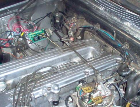 The O2 wiring routed along the firewall. It runs under the heat shield back past the transmission. Since this is a 2 BBL TBI I needed to either install 2 O2's (one in each pipe) or install the O2 into where the pipes merged. I went with the single. Since it was so far back in the exhaust system I went with a 4 wire Bosch unit. This is a heated unit so it won't lose the temperature during idle or low cruise. A three wire (no return to the ECU, just a signal, heat power and heat ground) could be used with the same results. I used the 4 and ran a return to the ECU because I had some flaky problems with my M117 conversion regarding a consistent O2 signal and I figured I'd try to eliminate it. My M115 uses a single wire because it is a single injector TBI and it's mounted within 6 inches of the exhaust manifold so no need for a heated unit. 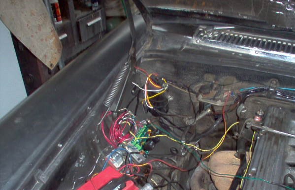 The fuel pump and filter mounting will be the same as I did on my M115 which is shown in the other thread. I haven't done them yet because of course, I just filled the tank up before I started this project and I'm going to wait until it's below a 1/4 of a tank to pull the lines. I've been driving it around and I must say I'm impressed with the smoothness of the car. I've got a slight "stick" in the linkage coming off idle. Gotta smooth that out but otherwise it just zooms along. A lot more even power curve than the carb ever was and it was a darned good carb. Getting the tuning done now and learning a lot about the Tuner Studios software. Next step, converting to a Ford EDIS wasted spark ignition. I should do it first on the M115 but I'll probably do it on the M110 since I have the loose engine sitting there which makes it a lot easier to fabricate parts.
|
|
#8
08-12-2011, 06:38 PM
|
|||
|
|||
|
Quote:
|
|
#9
08-12-2011, 09:49 PM
|
|||
|
|||
|
Looks like a relatively painless installation. I've been using MS2 extra firmware with a lot of success. They've incorporated 16x16 ve tables and a lot of MS3 features into this firmware. Currently on V3.1.2. Good luck.
__________________
CENSORED due to not family friendly words
|
|
#10
08-12-2011, 10:50 PM
|
|||
|
|||
|
Yeah, there's a long, painful, complicated story I have regarding the MSII-Extra code. I'd truly love to have the 16X tables but it was a 2 week ordeal upgrading to the 2.905 or whichever version it is I actually have. It involves Linux, Tuner Studio, Easy-therm, Windows XP, 2000, Vista and MegaSquirt's "easy to update" firmware
Bring a barrel over and I'll give you the story. 
|
|
#11
08-13-2011, 05:49 AM
|
|||
|
|||
|
I've had my fair share of gripes with MS2 extra mostly around the idle control setup. Fortunately enough people complained that somebody came up with a rival version of the firmware that resolved those issues. MSextra gets rid of easytherm all together. CLT calibration is a drop down menu with about a dozen examples already stored. I have a GM air temp sensor and MB CLT using VW L jet calibration.
__________________
CENSORED due to not family friendly words
|
|
#12
08-22-2011, 02:25 PM
|
|||
|
|||
|
fuel economy?
|
|
#13
08-22-2011, 09:05 PM
|
|||
|
|||
|
At the moment it's hard to gauge the economy. I was busy playing around with the tuning of the ECU when I did something stupid. I was concerned with the noisy tach signal I was getting from my Crane XR700 so I decided to convert over to spark control mode run by the MS controller.
Don't do it! The Crane opto receptor can not handle the straight +5V voltage put out by the ECU. It goes, "poof" and doesn't work any longer. I've got a "Hot Spark" ignition unit, essentially a Pertronix system, ordered and hope to have it installed and back to running this weekend. My initial impression is the mileage is considerably better than what I was getting with my Holley conversion carb. It might just be me being optimistic and I really haven't given it a good long test but I drove the snot out of it for a week and used only a quarter of a tank. The set back gave me time to mount the fuel pump at the rear of the car where it belongs so something good came of it. Last edited by Mike D; 08-23-2011 at 10:21 AM.
|
|
#14
11-22-2011, 07:29 PM
|
|||
|
|||
|
injector size
First off, thanks for documenting your conversion so well. I am planning to do the same thing and I have a couple of questions.
On the GM TBI unit I found 2 different sizes. One for a 2.8L engine and than one for the 4.0/5.7 Liter V8 engines. Which one did you choose? Since you are covering 2 of the wholes in the intake, do you feel the engine starving for air at high rpms? What is the injector size/ part nr did you installed? What is the PWM value at idle, cruise and WTO? Do you feel that it is the right size? And last question: Reliability Do you feel like this could be a daily driver? Thanks so much for you feedback
|
|
#15
11-29-2011, 10:39 AM
|
|||
|
|||
|
There are actually three different sizes. One for the 2.8L, one for the "performance engines" and one for everything else.
The 2.8L's one is rare. I would have used it if I could find one but I had to settle for the "everything else" one. The only difference is in the venturi size between the "performance" and regular one. One is 13/16" inch and the the other is 7/8". The one I used is the same as used on every GM engine from the 3.8L to the 7.0L so I know I have enough airflow, in fact I feel I have too much at idle but certain trade offs must be made. I used the standard injectors for the TBI unit. I believe it is for a late '80's early '90s Chevrolet with the 3.8L. Those injector number all cross reference to the same replacement injector anyway. The GM dealer is the only one who pays any attention to different injectors. The holes aren't "covered". Both the front and rear apertures open into the same chamber so the fuel mix is the same under engine demand. I keep changing the PWM 'cause I am not smart enough to leave well enough alone. Of course, being able to tune on the fly is half the fun.I am using it as my "daily driver" as well as the M115 and the M117's I've converted. The M115 (250C) is dead rock steady and has been for three years. The M117 ('85 W126) has been the "family sedan" for a year now and I drive the M110 (280C) every day, so, I'd say "yes" on the reliability factor. I'll be posting some updated pictures on the latest on the M110 later today.
|
 |
| Bookmarks |
|
|


 Linear Mode


