

|
|
|
|
|
|
#1
 02-24-2019, 05:02 PM
|
||||
|
||||
|
DIY: M110 Crankshaft Seal R&R
Like all seals in vehicles that are 20 years or older, the engine Front Main Seal is prone to failure. The rotary seal mounts in a housing and surrounds a turning shaft. The lip always faces the fluid it seals in, and the garter spring provides gentle pressure between the lip and the shaft. With age or mileage, or a combination of both, the seal will lose that ability. The seal may harden due to heat, it may lose its original tolerances through wear due to the constant rotation of the shaft, or the seal may loosen from the casing in which it is installed. If signs of leaking oil are present, it is probably time to replace the seal.
To use an old cliché, There is more than one way to skin a cat! Many methods have been used to R&R the Front Main Seal, with varying degrees of success. The MB FSM (Factory Service Manual) shows Special Tools which are utilized for the job. Some of these tools are cost prohibitive for the average weekend wrencher, who will only undertake this repair once. Very understandable! Thus, some ingenuity and creativity may come into play when replacing the Front Main Seal. Less expensive generic tools can be used, and some may be available from the local parts suppliers on a rental basis. I wont get into all the various methods, but will focus on what I have used. In this article, I will show the Crankshaft Seal R&R utilizing the Special Tools per the FSM, which I am fortunate to have access to. I must say, using these tools, there was little struggle. The Special Tools did perform as designed and simplified the whole job. Some preliminary phases of the job (IE Fan removal, Radiator removal, Belt Removal, etc.) are not described here, as they have been covered in other articles, and are Engine 110/ Chassis-model specific. The MB parts numbers listed are for my particular application, Chassis W123.053, and Engine M110.984. They may or may not be applicable to your particular Chassis/Engine. Its difficult to put a time on this job. I worked slowly. In addition to the Front Main Seal, I chose to install a new Spacer Ring (which the Seal rides on), a Water Pump, the illusive Water Pump Hose, Hardware, Belts, and a few more odds & ends. The car is a Concours car, so cleaning up and detailing the front of the engine was in the plan. The Fan, Counterweight, and Vibration Absorber were cleaned and painted. Much time was spent beyond the basic Seal repair. Without the Special Tools, the job would have taken me much longer, without a doubt. OK, time to get dirty. Lets begin. VEHICLE: Mercedes-Benz 1978 280CE. Chassis - W123.053. Engine Class - M110.984 SYMPTOMS: Oil leak emanating from Crankshaft Front Seal and signs of oil behind Crankshaft Counterweight and front of Oil Pan. OBJECTIVE: Remove and Replace Front Main Crankshaft Seal. Remove and Replace other Optional Components. PARTS: * Seal & Associated Parts Seal Ring (0039970347) Spacer Ring (1100310051) Dowel Pin X 2 (000007008244) Disc Spring X 4 (1279930026) Screw (308676018001) Screw X 6 (000912008210) Washer X 6 (000433008406) * Optional Water Pump & Associated Parts Water Pump (1102001720) Water Pump Gasket (6162010080) Screw X 5 (914141006300) Breather Line (1102000258) Hollow Screw X 2 (915036005100) Seal Ring X 2 (007603-008100) * Optional Hose Hose Thermostat Housing to Water Pump 45 mm (900271042012) Hose Clamp X 2 (0069972690) Gasket Thermostat Housing (1102030280) Screw X 3 (000912008067) Spring Washer X 3 (000137008204) * Optional Drive Belts Belt Alternator/ Water Pump - 9.5 X 960 (006 997 18 92) Belt Refrigerant Compressor - 12.5 X 1285 (005 997 98 92) Belt Power Steering - 12.5 X 825 (0069973692) Belt Air Pump - 9.5 X 825 (0029975792) SUPPLIES: Permatex High Temp Sleeve Retainer #64000, Permatex Water Pump & Thermostat Housing Gasket Maker #22071, Victor Reinz Reinzosil (Equiv MB 003 989 98 2010). Wet-or-Dry 320, 400, & 600, Lacquer Thinner, Mineral Spirits, Isopropyl Alcohol, Acme Finish #1 FT220 Wash Solvent, Q-Tips, Shop Rags, Paper Towels. Aerosol Rust Converter, Aerosol Flat Silver Paint, Aerosol Satin Black Paint, & LUCAS RedNTacky #2. Anti-Freeze 1.75 Gallon, ATF Dexron/Mercon 16 Ounces. (*** No endorsement of any products used is being made or implied***) SPECIAL TOOLS: Puller/ Installer MB 116 589 10 33 00 Flywheel Lock - MB 110589004000 Extractor - Sir Tools M0033 Mounting Tool MB 110 589 07 61 Torque Wrench ¾ Drive 100-600 Ft. Lbs. - CDI 6004MFRMH Crankshaft Counterweight Centering/Adjusting Tool Shop Fabricated Prior to Commencing, I highly suggest: Taking pictures as you go along, and, Dont throw away any parts till the entire job is complete! First, Drain Radiator of Coolant. Some people have performed the Crank Seal R&R with the Radiator in the vehicle. Since I was replacing several cooling system components, the coolant needed to be drained. Also, the Puller/Installer tool required clearance. Remove Hoses from Thermostat Body and Lower Pipe. My Radiator has an inboard oil cooler for the transmission. (Your vehicle may differ.) The Cooler Lines needed to be disconnected. I opted to disconnect the flex lines from the hard lines at their union, rather than at the Radiator. A Flare-nut wrench is highly recommended, so as to not round-off the soft fittings. Hint Use baggies with tie wraps around all open pipes/ hoses/ fittings. This will keep out dirt and keep you dry. Loosen Fan Shroud. Remove two clips that secure the top of the Fan Shroud to the Radiator. Hint Cut a piece of cardboard the size of the inner radiator surface. Carefully place it inside the Shroud between the Radiator and the Fan blades. Insurance. Remove Fan and Clutch from Water Pump Pulley. Remove the four 10 mm bolts that connect the Clutch to the Water Pump. These can be a pain. Try not to round-off the heads. Hint - A ground down 10 mm box head wrench will help and save the bolt heads. Move cautiously so the fins of the Fan do not contact the radiator. This is where the cardboard protector comes in handy. Remove Fan Shroud. Expect a little twisting and turning, as you lift up. Remove Radiator. Remove two clips which support the Radiator to the radiator support. Carefully lift Radiator upward and out of the two lower Rubber Mounting grommets. Hint Place the piece of cardboard you cut earlier against the A/C Condenser Fins. Remove Drive Belts. This requires loosening the tightening nuts and adjustment bolts on all the accessories. In my case, these were the Alternator/ Water Pump, the Refrigerant Compressor, the Power Steering, and the Air Pump. These vary from model to model. As I recall, mostly 17 mm and 19 mm sockets and box end wrenches were used. Remove Drive Pulley and Vibration Absorber. These are secured to the Counterweight with six Allen head bolts. Use a 6 mm long Allen socket. The Allen may twist due to torsion. I used a 6 mm Allen on a 10 mm shaft, which eliminated this twisting effect. Hint - Slightly break each bolt loose, one at a time, then proceed to remove all six. The Pulley should pull off without problem. The Vibration Absorber may require several taps with a rubber mallet. Insure that when it becomes free, it does not drop and damage itself. Additional Access. This is when I removed the AC Belt Tensioner and later the Thermostat Housing. Since I was working from above (no lift), I wanted good visibility and tool access. Hint Plug the Thermostat Housing opening. If it can fall in, it will! 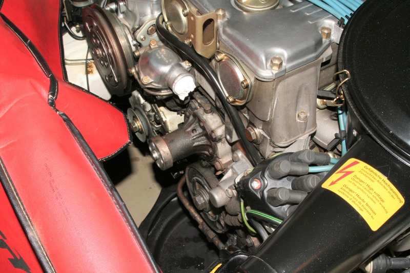 Remove Water Pump Pulley and Water Pump. I planned on installing a new Water Pump, so removal was a logical step. Five bolts hold the Water Pump to its housing. Mine were not rusted. If you have rust, treat them with a product of your choice, and let the penetrant do its job. Unscrew with caution. Hint Once the Water Pump is removed, cover the opening. If it can fall in, it will! BLUE Arrow = Water Pump. RED Arrow = Counterweight. YELLOW Arrow = Crankshaft Bolt. 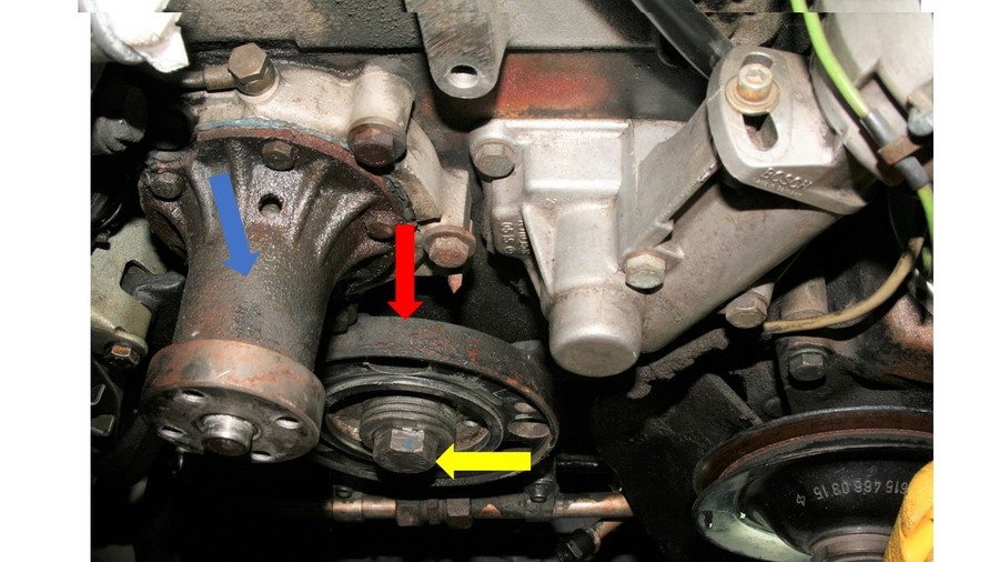 Attach Flywheel Lock. To be on the safe side, the engine was set to -0- TDC. I used the Locking device which mounts in the Flywheel Inspection Cover. The Inspection Cover was removed, two lower Bell Housing bolts were removed, and the Flywheel Lock was set in place. The teeth of the lock engage the Flywheel, and inhibit its rotation. A flywheel lock is also available which requires starter motor removal. Other creative methods have been utilized. 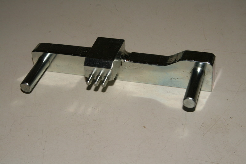 Flywheel Lock - MB 110589004000 Remove Crankshaft Nose Bolt. With the Flywheel Lock securely in place, the bolt can be removed. Since the Bolt on the 110.984 is torqued to 400-450 Nm, I utilized a ¾ drive Torque Wrench and 27 mm deep socket to remove the Bolt. It came out fairly easily with a 40 handle on the Torque Wrench. I suspected that the Seal had been previously replaced and the Bolt not necessarily torqued to spec. Another method to loosen the bolt is to put the socket on a breaker bar, wedged against the frame, and bump the starter. BLUE Arrow = Water Pump. RED Arrow = Counterweight. YELLOW Arrow = Crankshaft Bolt.  RED Arrow = Dowel Pin. GREEN Arrow = Vibration Absorber guide pin. 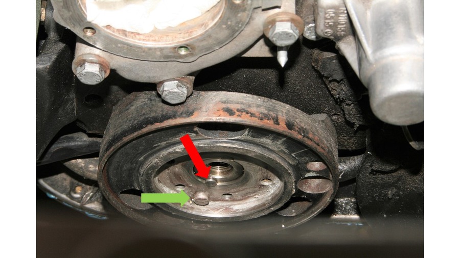 With all components removed, I had much more access to the Counterweight and Crankshaft Nose Bolt. This gave me room to muscle the 40 Torque Wrench handle. RED Arrow = Thermostat Housing. BLUE Arrow = Hose Connection Water Pump to Thermostat Housing. PURPLE Arrow = Breather Line Connection. GREEN Arrow = A/C Belt Tensioner Mount. YELLOW Arrow = Water Pump Mounting. ORANGE Arrow = Counterweight. 
__________________
Gute Fahrt 
|
|
#2
02-24-2019, 05:04 PM
|
||||
|
||||
|
Pull Counterweight from Crankshaft Nose. This is where the Puller is used. Depending on exactly which tool and method you use, you will proceed accordingly. The Special Tool I used had a threaded body with a central bolt with a pivoting end, that rotated against, but did not thread into, the Crank snout. The tool body also had three offset smaller bolts, which threaded into the Counterweight, where three of the (six) pulley bolts were attached. When turning the large bolt clockwise, the pivoting end remained stationary with regard to the Crankshaft nose and turned freely against it. This same clockwise rotation of the bolt caused the tool body to travel away from the Crank nose. Accordingly, the three bolts threaded into the Counterweight caused it to pull away from the Crankshaft, drawing it off the shaft. I hope this explanation makes sense.
 Puller/ Installer MB 116 589 10 33 00 Seal and Spacer Ring Prior to Removal. Note The old Seal has a half-shoulder, which is located with the shoulder in the upward position. The FSM Section 03-324 Replacing Front Crankshaft Radial Oil Seal, states in a NOTE: Radial Sealing Rings with a half-round shoulder are provided for oil pans not milled flat. Install radial sealing rings with all-around shoulder only in engines with oil pans milled flat.  Pull the Old Seal. This was pretty self-explanatory. I used a combination of seal removal tools. The old seal was hard. No pliability at all. Upon observation, my Oil Pan was milled flat, and should have had the radial sealing rings with all-around shoulder. RED Dotted Line = Mid-point of Seal location, showing Oil Pan and Engine Block juncture. GREEN Arrow = Shows Oil Pan which was milled flat.  Remove Spacer Ring. I had read horror stories about getting the old Spacer Ring out. I must say, the Extractor Tool I used worked quickly and efficiently. It is basically a collet, which is a chuck that forms a collar around the Spacer Ring and exerts a strong clamping force when it is tightened. The old Spacer pulled out so easily that I thought the Extractor had slipped and lost its grip. Total elapsed time . Maybe 2 minutes. Once again, other folks have used screwdrivers and the like to get the Spacer Ring off. I can only comment on what I have done. RED Arrow = Spacer Ring being gripped by collect of Extractor Tool.   Extractor - Sir Tools M0033 Spacer Ring and Crankshaft Seal. The Seal was hard, and additionally the wrong style. It had a half shoulder, but clearly the FSM shows that it should have been a full shoulder. The Spacer Ring is scored. I opted to replace. GREEN Arrow = Score marks from Seal Lip.  Prepare for the Crankshaft Seal and Spacer Ring Installation. I plugged inside the Seal opening with a shop rag, so as to prevent any of the old Seals adhesive shreds from dropping inside. I removed the old adhesive with a pick. Then the opening was cleaned with Lacquer Thinner, wiped dry, and cleaned again with pre-paint Wash Solvent to remove any residue. I polished the Crank snout with 600 wet-or-dry. Wiped clean and residue removed. HALFTIME Provide your own Musical Entertainment. Painting. Before reassembly of all parts and hardware, I decided to dress-up some of the components that I was reusing. These were the Fan Blades, the Counterweight, and the Vibration Absorber. They were in relatively good condition, but needed to look better. I opted to paint the Fan Blades flat silver, and both the Counterweight & Vibration Absorber satin black. I de-greased all parts, then proceeded to prep the surface with 320 paper. The parts were cleaned with Wash Solvent, suspended with old coat hangers, and sprayed with Rust Converter/ Primer. After 24 hours dry-time, they were painted with three lights coats of top coat. Allow 24 hours before handling.  Crankshaft Seal Installation. Mating surfaces the Engine Block, the Upper Oil Pan, and Seal were cleaned with Isopropyl Alcohol. Hint Dont use Rubbing Alcohol which can contain Glycerin. Look for the 91% bottle at your local pharmacy. Hint Apply a small amount of tacky grease to the garter spring. This is particularly important if you will be tapping in the Seal. The shock transmitted from the hammer head can displace the small spring, and ultimately cause a seal failure. Since I was using a puller, this did not apply to me. However, it couldnt hurt! The Reinzosil sealant was applied to the outer edge of the Seal, and behind its full shoulder. Cover the entire area, but dont overdo it. My rule-of-thumb was I wanted to still be able to see the ribs on the outer edge of the Seal. The sealant needed to just fill in between the ribs, in the recesses. The Seal was then placed onto the Mounting Tool, and the tool threaded into the Crank nose and slowly tightened till the Seal shoulder was drawn in and seated snugly against the Bore. If you applied the right amount of sealant, you should just see a small bead (1-2 mm.) of it squeeze out around the circumference of the Seal. Per the FSM, I left the Mounting Tool in-place for three hours to give the adhesive sealer time to set-up and secure the Seal. GREEN Arrow = Sealing Ring on outer part of Mounting Tool. (Half-shoulder Seal shown for visual purposes only.) YELLOW Arrow = Spacer Ring on inner part Of Mounting Tool. Silver milled aluminum adaptor part of the Special Tool but unused. Mounting Tool MB 110 589 07 61 Spacer Ring Installation. The Mounting Tool was again used for this procedure. First, on the previously installed Seal itself, I filled the area between the Primary Sealing Lip, and the Secondary Dust Lip with tacky grease. The outer surface of the Spacer Ring was also lightly greased and was placed in the Mounting Tool Body. The Tools tightening bolt was threaded into the Crankshaft and tightened, causing the Spacer Ring to be drawn inward to its full installation position. So as to prevent any seepage of oil out from between the Crankshaft nose and the Spacer Ring (unlikely, but possible), I applied 1 or 2 drops of anaerobic Sleeve Retainer. Because of its thin viscosity, the liquid was drawn in around the outer edge of the Spacer Ring and the Crankshaft. A little dabll do ya. I intentionally did not saturate the inside of the Spacer Ring and the outside of the Crankshaft with the Sleeve Retainer, as the locking effect could make the Spacer Ring more difficult to remove, should it ever need to be replaced at a future time. (Hopefully not in my lifetime!) Between the Dust Lip of the Seal and the Spacer Ring there should be a small gap about 1 mm. I carefully packed as much tacky grease in this gap as I could. (The grease both lubricates the Shaft and keeps dirt away from the Primary Lip.) Excessive amounts of the grease were wiped clean. BLUE Arrow = Small gap between Spacer Ring and Secondary Dust Lip. YELLOW Arrow = Spacer Ring. 
__________________
Gute Fahrt
|
|
#3
02-24-2019, 05:06 PM
|
||||
|
||||
|
Thermostat Housing, and Water Pump to Thermostat Housing Hose. This particular Hose is almost always ignored. Radiator hoses and heater hoses are easy to access, and are easy maintenance replacements. The 45 mm Hose is not the case. While my fan, belts, and Thermostat Housing were already removed, the Hose was much easier to replace. Quite honestly, the old Hose looked original to the vehicle. The old clamps were rusted, and cutting them off was less struggle than spending an hour trying to unscrew them. I had two OEM MB clamps (45-55 mm) in my parts bins. Both new clamps were fitted mid-hose and slightly tightened, so I wouldn’t be fighting them from falling off, or worse, forgetting to put them on. One end of the Hose was slipped on the Water Pump Housing. Due to the short 45 mm length, there was no flexibility in slipping the other end over the Thermostat Housing, with it bolted to the engine. With the Thermostat Housing off anyway, installing the Hose to the Housing neck first, then bolting the Housing to the engine, was the plan. As with the Water Pump, I placed a small amount of Gasket sealer on the Thermo Housing and then placed the new gasket into the aligned position. A small amount of Gasket sealer was carefully placed on the mating Cylinder Head surface. In one continuous movement, the neck of the Thermostat Housing was then carefully slipped into the upper end of the Bypass Hose, and at the same time fitted against the Head, using three new Bolts & Washers for proper positioning. The Bolts were finger tightened. After 20 minutes, the Housing Bolts were torqued to spec (10 Nm.). The bypass Hose Clamps were then tightened.
 Time to Step Back and Admire Progress!  Counterweight and Dowel Pins. The perfect alignment of the Counterweight to the Crankshaft is paramount, otherwise, driving in the two ’locking’ Dowel Pins will not be possible. Where each of the two Pins is located, reside a mating semi-cylindrical milled bore, in both the Crankshaft snout and the Counterweight. (Imagine putting two half-moons face to face.) When perfectly aligned, a cylindrical bore is created. Each of the (slightly over-larged) Pins are driven into the recesses and basically mate the two half-bores (Counterweight to the Crankshaft) together. Hint – The locating Pins are slightly offset (not equally 180 degrees offset) on the Crankshaft, so the Counterweight will only fit properly one way. The Crankshaft was lightly oiled. Using your eyes and the location of the Pin recesses, slightly place the Counterweight on the Shaft. Again, visually identify that the Pin bores are aligned. If not, try to rotate the Counterweight. If so, begin to draw the Counterweight inward onto the Shaft using the old Nose Bolt and Spring Washers. If you get to a point where the Counterweight is pulled in and you see the alignment is off, you will most likely have to pull the Counterweight off, and start the process over. I was off by about 1 mm. The Dowel Pin would not even start to fit. I had a home-made Special Tool that made the alignment possible. Keeping in mind that my Crankshaft Lock was still in place, I attached my tool to two of the bolt threads in the Counterweight. I was (barely) able to rotate the Counterweight the 1 mm to get the Pin alignment that I needed. For verifying proper alignment, I used a (8 mm as I recall) brass drift, and moved it in and out of the aligned bores to confirm a smooth fit. Once alignment was confirmed, the Counterweight was pulled till it bottomed. The leading edge of the Counterweight’s shaft, as pulled onto the Crankshaft, has a small lip. This lip will push into the 1 mm gap between the Seal and the Crankshaft, that had earlier existed. Finally, insert and start both Dowel Pins, then use a brass drift to drive the Pins till they bottom. Some people have reported that the new Pins were longer than the originals, and required grinding down. The Pins I received were the same as the originals, so I fortunately avoided the ‘mod’. RED Arrows = Proper alignment of the Counterweight with the Crankshaft, showing the Dowel Pin bores.  RED Arrow = Dowel Pin showing fitting in Counterweight.  RED Arrow = Lip of Counterweight which abuts Spacer Ring and rides against Seal Dust Lip.  RED Arrows = Dowel Pins driven into place.  BLUE Arrow = Special Tool fabricated to rotate Counterweight on Crankshaft. 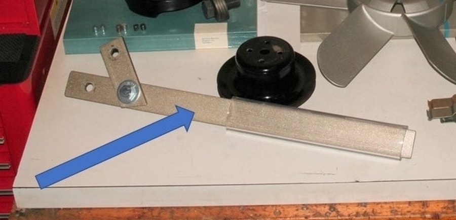 Install new Crankshaft Nose Bolt and Four (Belleville) Spring Washers. Hint – New hardware must be used. The old hardware is not reusable. Pay attention to the correct assembly of the four Washers – front-to-back, front-to-back, etc. The tightening of the Bolt is pretty self-explanatory. It sounds easy enough, eh. The FSM spec for the torque value is 400 – 450 Nm. (Check the FSM for your particular application for model-specific torque.) I tightened the nose bolt as much as possible with my ½” drive breaker bar. Then, I had to put on my ‘big boy’ pants. I used a 100 – 600 Ft. Lbs. ¾” drive torque wrench, with a 27 mm deep socket. The handle on the wrench is about forty inches long so I had good leverage. I started cranking, and cranking. Took a pause, then repeated. Took another pause, then repeated. I finally heard the ‘click’ I had been waiting for. What a beautiful mechanical sound. Lastly, the Flywheel Lock was removed, and the two transmission bolts and the Flywheel inspection cover were reinstalled. 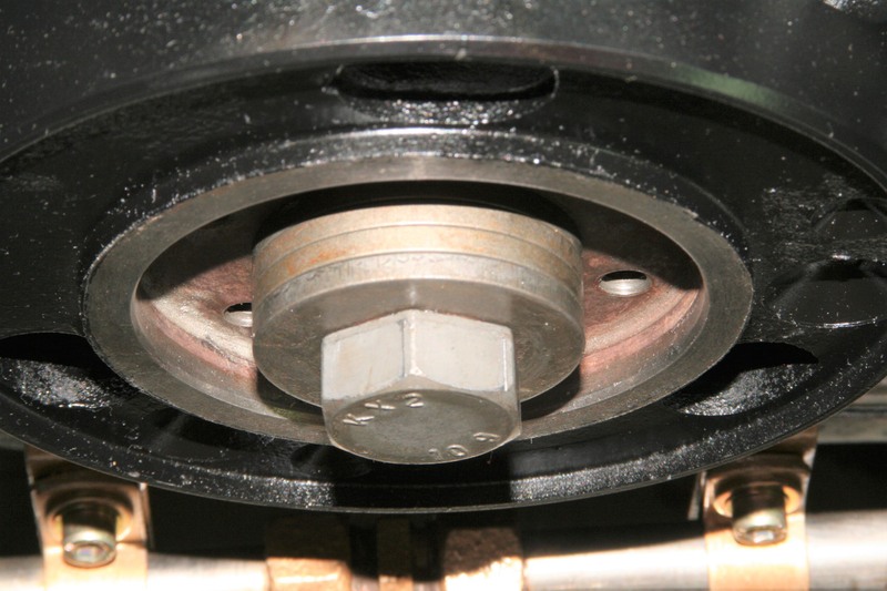  Install Water Pump. The surfaces of the Water Pump and Water Pump Housing were cleaned with Isopropyl Alcohol. While there are opponents to the use of sealant on water pumps and thermostat housings, I opted to do so. With caution. On the Water Pump, I smeared the thinnest possible amount of gasket sealer possible. I’m inclined to say the thickness of a piece of construction paper. Effort was made to clean excess from the edges and bolt holes. The gasket was centered and placed against the Water Pump. Moving quickly (as this particular product begins to ‘tack’ in about five minutes), I applied gasket sealant to the Water Pump Housing. The Water Pump was carefully guided into place, paying special attention to do disturb the placement of the Gasket. Five new Bolts and Washers were installed finger tight. After about 20 minutes, there were torqued to spec, 10 Nm. As I recall. Absolutely no gasket maker squeezed out when tightened, a good sign I had not over-applied the product.  Breather Line. Since the Coupe is a ‘show car’, I strive to ‘beautify’ when possible. The old Breather Line had lost its yellow cad plating. A NOS part was found at a very inexpensive price. The hollow Banjo Bolts and crush Washers were also replaced. One end was connected to the Thermostat Housing, the other to the Water Pump Housing.  Drive Pulley and Vibration Absorber. The Vibration Absorber and Counterweight were ‘keyed’ via a guide pin on the Counterweight. It only fit one way. The Absorber was put on by hand, as was the Drive Pulley. No tools were necessary. Six new Allen Head Bolts and Washers were installed finger tight. I tightened them in a star pattern to about 15 Nm., then torqued to spec (35 Nm) in a star pattern. RED Arrows = Guide Pin and Guide Pin Bore in Counterweight and Vibration Absorber.   From this Point Forward, assembly of removed parts was done in reverse order. This to include the A/C Belt Tensioner, Water Pump Pulley, Belts, Belt tightening adjustments, Radiator, Shroud, Fan, Reconnect Radiator Fluid Lines, and Top-Off Coolant and Transmission Fluids. Hard to see ‘down there’. It’s stuffed pretty full.  Hopefully, I have described the process correctly. I am not a professional mechanic and have never worked in a repair shop. I did the best I could. Unfortunately, during the course of the work, I did not get illustrative pictures of every single phase. Hopefully, the descriptions and images I provided present a good guide, never-the-less. Here is a link to my initial thread. Much thanks to the kind Members who took the time to reply, answer my ‘novice’ questions, and get me started on the Repair with good advice: M110 Front Main Seal Pushed Slightly Out
__________________
Gute Fahrt Last edited by mmiller; 02-24-2019 at 06:21 PM.
|
 |
| Bookmarks |
|
|


 Linear Mode


