

|
|
|
|
|
|
#1
 11-19-2008, 09:01 PM
|
|||
|
|||
|
M115 T.B.I. conversion
Well, I finally had it! I've had this engine since 1994 and it's been in four different cars. Dang thing won't die but it was cursed from the factory with twin down-draft Solex carbs. When it runs, it runs FANTASTIC! Of course, the sync'ing only lasts about 3 weeks so the way it works is; three weeks of "scalded dog", three weeks of,"well, it's running okay" and then followed by three weeks of," die already, you sack of *&^%"!
I've rebuilt them, planed the mating sufaces, re-threaded them, reworked the linkages twenty times, re-jetted them and every thing I could think of doing to them but it was time for them to go. The curses!  The curses removed. Look at the trail of fuel leaks from the throttle shafts. 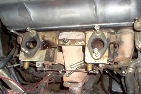 Check out how wet the intakes are and this is AFTER I pulled the carbs and manifolds! So figure on 45 minutes of sitting. 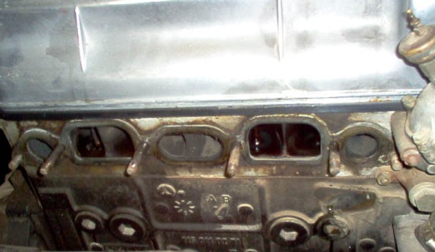

|
|
#2
11-19-2008, 09:17 PM
|
|||
|
|||
|
what tbi unit do you intend to use? with megasquirt?
|
|
#3
11-19-2008, 09:24 PM
|
|||
|
|||
|
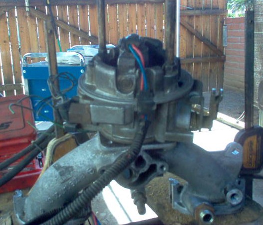
So I decided to go to a side draft manifold and use a throttle body injection unit from a GM 2.5L engine.
First things first, locating an intake. Thanks to Joe Alexander in Ohio (ja17 on the board) I got one. I figured I'd have to make an adapter plate but; miracle of miracles, they have the same size plenum and the mounting holes are almost the same! The new manifold and TBI unit.  These two holes need to be drilled and heli-coiled to 8MM X1.25 thread for the mounting studs.  Manifold drilled, heli-coiled and ready for the fitting of the TBI.  Cleaning up the crappy GM casting holes. 13/32" drill.  No metal removed, just clean holes! 
|
|
#4
11-19-2008, 09:34 PM
|
|||
|
|||
|
First fitting of the TBI unit to the manifold.
 Hmmm, there seems to be a fly in the ointment! The round hole in the gasket is for the Idle Air Control stepper motor.  Two ways around this, either seal the vacuum port to the IAC and use a remote IAC or make a plate.  I made a plate 'cause I'm a cheap SOB! The IAC port on the TBI unit. 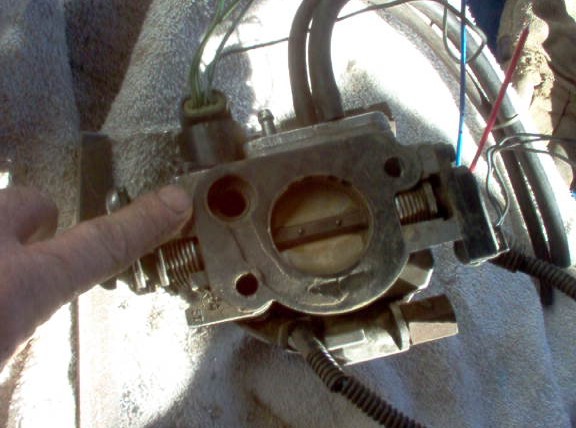 The initial plate. I trimmed it down so's it didn't look like a "barnyard special". 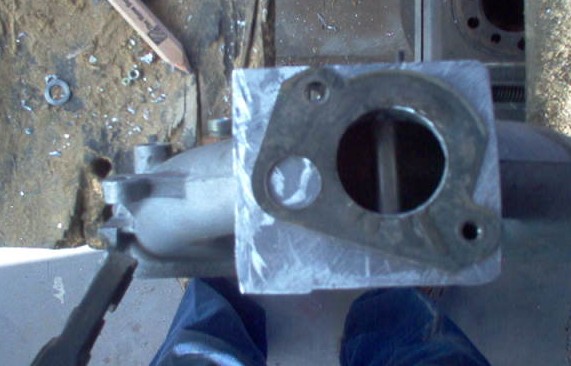
|
|
#5
11-19-2008, 09:49 PM
|
|||
|
|||
|
The plate after some trimming.
 The plate with the TBI unit attached.  Side view. You can see just the edge of the plate but I didn't want to remove any more of the plate because it's some aluminium flat stock I had handy. It's about 1/8" thick and I am concerned with warpage. A little thicker and I would have formed it right to the edge of the TBI. It's not a critical area since the IAC is actually a "designed" vacuum leak but I figured, "better safe than sorry". 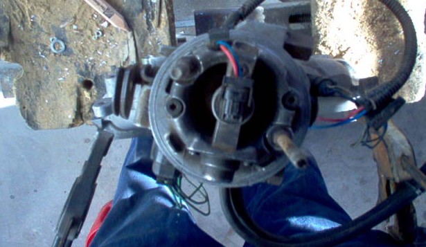
|
|
#6
11-19-2008, 10:03 PM
|
|||
|
|||
|
Okay, now on to the next problem. If you already have the side draft Stromberg then you can ignore the next four pictures. Unfortunately, I had the twin Soloex'es and found this out the hard way. The heat risers must be sealed. A few thin layers of furnace cement.
 Cured using a heat gun. Thin layers are the key!  One side plated and the other one filled to the edge.  Manifolds mounted. The black will flake off as it is heated.  The bung installed for the O2 sensor. I chose the upper pipe as it has the shortest "run". The 2.5L TBI is a single injector so it doesn't make sense to use two O2 sensors. 
|
|
#7
11-19-2008, 11:58 PM
|
||||
|
||||
|
Please keep us posted because I want to change out the carbs on my 220S. What GM car did you get the TBI from? how much did the FI system cost you?
__________________
Regards Warren Currently 1965 220Sb, 2002 FORD Crown Vic Police Interceptor Had 1965 220SEb, 1967 230S, 280SE 4.5, 300SE (W126), 420SEL ENTER > = (HP RPN) Not part of the in-crowd since 1952.
|
|
#8
11-21-2008, 08:40 PM
|
|||
|
|||
|
Dam that's wayyyyyy cool!! I want one!!
|
|
#9
11-22-2008, 09:33 AM
|
|||
|
|||
|
Back at it!
I used a Megasquirt II V.3.0 PCB kit which I assembled for the ECU which will be mounted under the passenger side dash behind the glovebox. I purchased a Megasquirt relay box and their cable for simplification of wiring. You could use a standard GM ECU for the conversion with a couple of small additions. You need to add a road-speed sensor and a lot of the connections won't be used. I liked the ability to program the ECU using a laptop computer and the tuning programs. The relay board and wiring bundle was a big selling point. The labels are printed on the wires themselves and that made it so much easier. The first thing was mounting the relay board. I removed the old emissions solenoids from their bracket, removed the bracket, straightened the fold, drilled mounting holes for the board, painted it and re-installed to the fender. 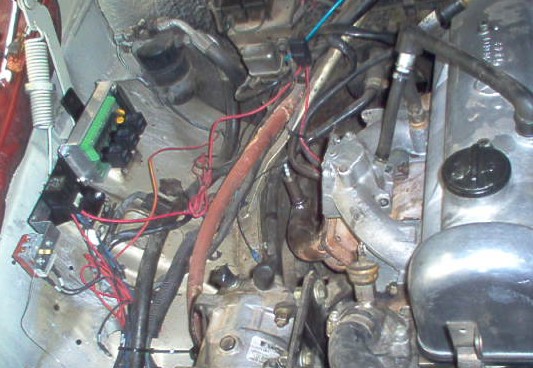 The wiring mess beneath the new board is from an electric fan installation. It'll be cleaned up with the TBI conversion. The next step was to route the relay board to ECU cable, cut it for length, solder the wires and connection. I ran the cable through the existing rubber grommet and soldered the connection but it's a pain and not reccommended unless you are adept at soldering and have the proper soldering pencil. You can solder the end on a bench and finesse the cable through the hole gently. I had to cut the center rubber on the grommet and will need to re-seal it when I am done. The left over, clearly labeled, wire is used for the connections between the sensors and the relay board. Sweet! The relay and switch to the front of the board are for the electric fan. The O2 sensor is in an easy to access location. A few wires are already connected in the picture.  Spaghetti anyone? It's not as bad as it looks but imagine trying to do this without colored, labelled wires! I stripped the wires from their loom for length, routing and bundling purposes. 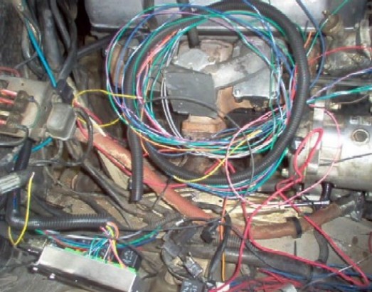 All right! That's better! The main bundle has been routed neatly, the wires are separated, coiled and located in their approximate locations. The battery 12V line is connected at the starter, routed through the bundle and connected to the board. The provided ground wire in the bundle was partially pulled out of the cluster, spliced to the main ground strap (braided copper wire between the engine and the body, right rear of the engine), connected to the relay board and fed back through the loom for the fuel pump ground.  It's starting to look like an engine again as opposed to a misfit yarn repository. Here's the GM standard coolant temperature installed in the thermostat housing. You lose the overheat fan sensor if you install it here. I didn't care because I already have a thermostatically controlled electric fan. It would be easy enough to install a short section of PVC tubing with a 3/8" NPT bung in the upper radiator hose. The M115 does not have any available plugs in the head to simply remove and install the sensor. You have to drill the housing with a 9/16" bit and tap it to 3/8" NPT. Not an easy task as there isn't much excess metal to work. I'd suggest taking it to a machine shop and having them do it. The sensor wires are just twisted together in a loop until I have all the sensor wiring in place.  So far, the most aggravating part of this conversion is the routing of the wires. You get everything in place and you look back and think," How did I miss those wires rubbing up against that vacuum line/brace/ tangled together,etc."? I've spent at least three hours pulling wires out of the loom, rerouting them and stuffing them back into the loom. PITA but it's gotta be done right if you're going to do it. p.s. Notice the Sanden A/C compressor with the adapter bracket. Best thing you can do for your older A/C system. uses very little power and works better than the old York "thumper". Last edited by Mike D; 11-22-2008 at 09:45 AM.
|
|
#10
11-24-2008, 09:37 AM
|
||||
|
||||
|
You're probably going for something a little less "hacked" but I thought this surge tank was genius:
http://www.geocities.com/hrayhouston/antisurgetank.html I've noticed most of the 2.5L units have a cable throttle, are you changing to that or converting it to linkage?
__________________
___ /<>/>/> 1967 230S automatic Boston, MA
|
|
#11
11-24-2008, 10:59 AM
|
||||
|
||||
|
I might be missing something, but is the pickup point really that low on a carbed w114/w115? Seems like if it would become uncovered with the inline electric pump it'd do the same thing while picking up fuel for a carb?
I'm assuming one using the stock pickup point and plumbing in an inline pump.
__________________
One more Radar Lover gone... 1982 VW Caddy diesel 406K 1.9L AAZ 1994 E320 195K
|
|
#12
11-24-2008, 06:55 PM
|
|||
|
|||
|
I had originally planned for a surge tank and I might still end up with one but I don't think it will be needed. The best place to put one in the 250C woud be in the RF fender well behind the headlight. I can't see running the fuel lines across the engine and then back to the TBI. It would still need an electric pump to feed the tank. The mechanical pump wouldn't be consistent enough to deal with the flow because the TBI fuel return needs to feed to the tank for heat reasons. Seemed redundant.
I am going to use a cable feed. I'm tired of messing with those verplunkt linkages, bell cranks and bushings. I will incorporate the bracket with a "stand-off" for the wiring loom. As far as I can tell, the W114/115 only used one tank in both the standard and "E" engine bodied cars. The pick-up is on the very bottom of the tank. I might need to install an accumulator or baffle to smooth out the flow but only time will tell.
|
|
#13
11-24-2008, 08:59 PM
|
|||
|
|||
|
Back at it.
There's the pesky IAC to deal with. The original GM manifold has a vacuum channel built in. The plate I made doesn't have one. The gasket sitting on the base of the TBI.  I have to create the vacuum port so a quick "snip-snip" through the gasket connecting the IAC to the venturi. It doesn't need to be large. Keep it in the narrowest flange area you can.  Here's the amended gasket ready for installation. 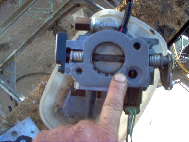 TBI in place with lines formed (Dorman part numbers 800-151 and 800-153). Don't bother dealing with the parts guys, just TELL them what part numbers you want. They'll give you statements such as, "That is for a "quick-connect" or, that is a fuel line repair kit".  I had bent the lines perfectly to fit around the valve cover and thought I was "hot ****". This is a picture of me holding the cut-off portion. Man, it looked sweet! 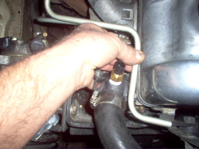
|
|
#14
11-24-2008, 10:29 PM
|
|||
|
|||
|
So, after I made those snazzy little lines and my head swelled, I looked down. Hmmm, now HOW am I supposed to change the thermostat without having to undo the fuel lines from the TBI and ruining the O-rings everytime? Oh well, cut them back. I can change the thermostat now by undoing the rubber lines. "The best laid plans...."
 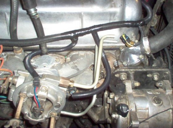  The wiring is beginning to come together and actually look like it belongs. I'm not a big fan of the shiny electrical tape but it does the job. The connections are all soldered and shrink-wrapped but the spots where the looms join and end have to be sealed.  Once upon a time there actually was a work cart beneath this towel. 
|
 |
| Bookmarks |
|
|


 Linear Mode


