

|
|
|
|
|
|
|||||||
 |
|
|
LinkBack | Thread Tools | Display Modes |
|
#1
 09-12-2012, 08:58 PM
|
||||
|
||||
|
Replacing the injection pump vacuum shutoff box, 1975-1976 300D W115.114
Project: Mercedes W115.114 Replacing the injection pump vacuum shutoff box.
Time = 7 hours Cost = $211 Skill level = 5 Tools: Wrenches, sockets, screwdrivers, razor scraper, dental floss, drain pan, paper towels, hose fitting plug Applicable Years: 1975 - 1976 Parts: New shutoff box and gaskets Tip: Wear Nitrile gloves Performance Gain: Vehicle shuts down with key If the engine fails to shutdown, and you have verified 13 – 30 inches of vacuum is supplied to the vacuum shutoff box. You have tried using a hand held vacuum pump directly on the shutoff box, and it fails to hold vacuum (minimum time is 60 seconds with no loss). The injection pump vacuum shutoff box diaphragm has broken and the vacuum shutoff box must be replaced. In this article, we will go over the procedure for replacing the injection pump vacuum shutoff box on the W115.114 300D naturally aspirated OM617. #1. Pull the hood release lever. #2. Pull the secondary hood release lever, and raise the hood. #3. Take pictures before you start, with special attention to throttle linkages, brackets, and vacuum routing. #4. Disconnect the vacuum supply line from the brake booster. (to avoid damage). #5. Remove the throttle link plate from driver side top center of the valve cover, disconnecting the linkage. (for better access). #6. Remove the steel injector lines. #7. Cover the delivery valve ports. #8. Cover the injector ports. #9. Remove the heater return line from the cylinder head and heater valve, capping the cylinder head fitting. (for better access). #10. Remove the vacuum line from the shutoff box. #11. Place a drain pan "centered" under the rear of the injection pump. #12. Remove the six flat blade screws retaining the injection pump rear cover plate. #13. Rap the top edge of injection pump rear cover plate with the handle of a large screwdriver, hard enough to separate the rear cover plate from the injection pump. #14. Gently work the injection pump rear cover plate through various angles, until the shutoff box hooked leg disengages from the injection pump rack. #15. Remove the injection pump rear cover plate from the vehicle. #16. Using clean paper towels, carefully stuff them in rear end of the injection pump. #17. Scrape all trace of old gasket from the rear-mating surface of the injection pump. #18. Remove the used towels from the injection pump, dropping them into the drain pan. Taking extreme care that no debris enters the injection pump. #19. Cover the open end of the injection pump with a plastic bag. (To prevent random debris entering). #20. If the injection pump rear cover plate gasket came off intact, it can be used as a template to cut a new one from sheet stock. Failing that, you will need to order new gaskets. #21. Remove the two flat blade screws on the inside of the cover plate, retaining the shutoff box. #22. Remove the shutoff box from the cover plate. #23. Remove all trace of old gasket from the inside and outside of the cover plate. #24. Install the shutoff box with a new gasket onto the cover plate. #25. Install and tighten the two flat blade screws on the inside of the cover plate, retaining the shutoff box. #26. Use dental floss or sewing thread to install - tie the new injection pump gasket to the cover. (It simplifies installation). #27. Install the injection pump rear cover plate to the vehicle. #28. Gently work the injection pump rear cover plate through various angles, until the shutoff box hooked leg engages the injection pump rack. Note: When it catches, you can gently pull the plate assembly to the rear of vehicle and feel the rack spring resistance - return. Warning: If the shutoff box fails to engage the rack correctly, it can jam the injection rack at full throttle. #29. Install and tighten the six flat blade screws into the injection pump rear cover plate. #30. Remove the 19 MM plug from the top of the injection pump. #31. Add one pint of fresh engine oil. #32. Install the 19 MM plug into the top of the injection pump. #33. Remove the drain pan "centered" under the rear of the injection pump. #34. Install the heater return line from the cylinder head and heater valve, removing the cap from the cylinder head fitting. #35. Install the vacuum line onto the shutoff box. #36. Remove all covers from the delivery valve ports and injector ports. #37. Install the steel injector lines. #38. Install the throttle link plate onto driver side top center of the valve cover, reconnecting the linkage rods. #39. Install the vacuum supply line onto the brake booster. #40. Top off the coolant level, and you are ready to test your repair. . Last edited by whunter; 09-30-2012 at 05:28 PM. 
|
|
#2
09-24-2012, 09:03 PM
|
||||
|
||||
|
Replacing the injection pump vacuum shutoff box:
Picture 1 Passenger compartment hood release. 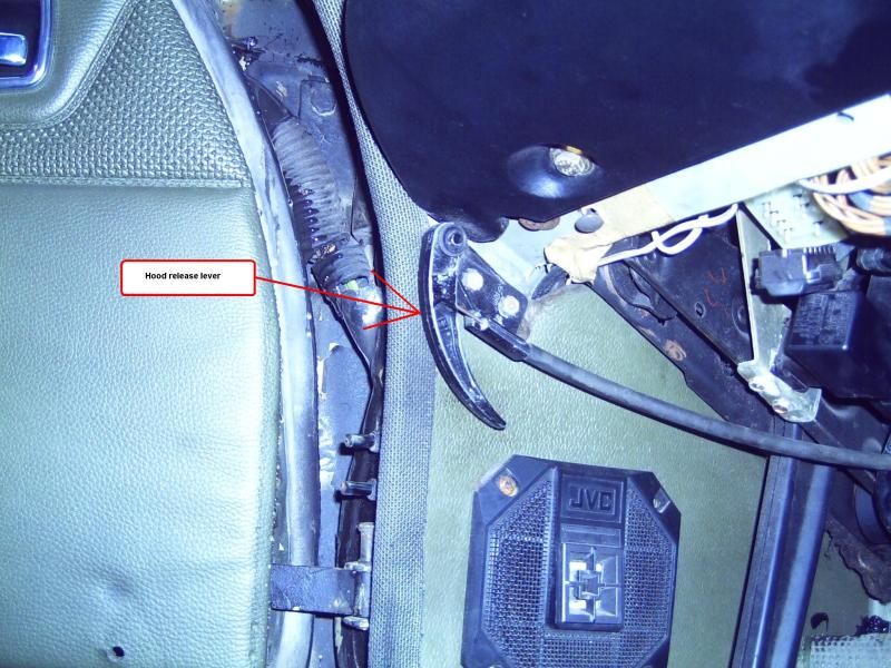 Picture 2, 3 and 4: Secondary hood release. 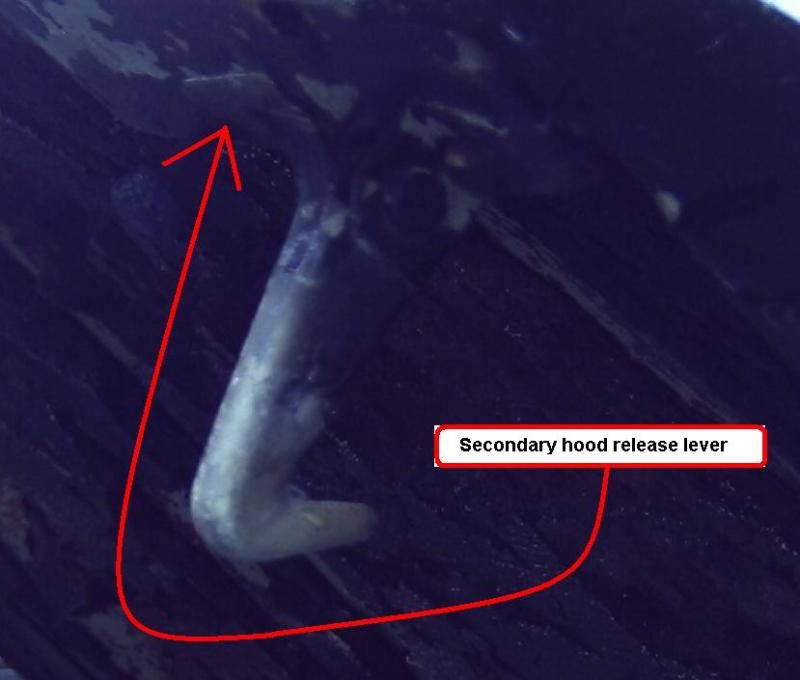 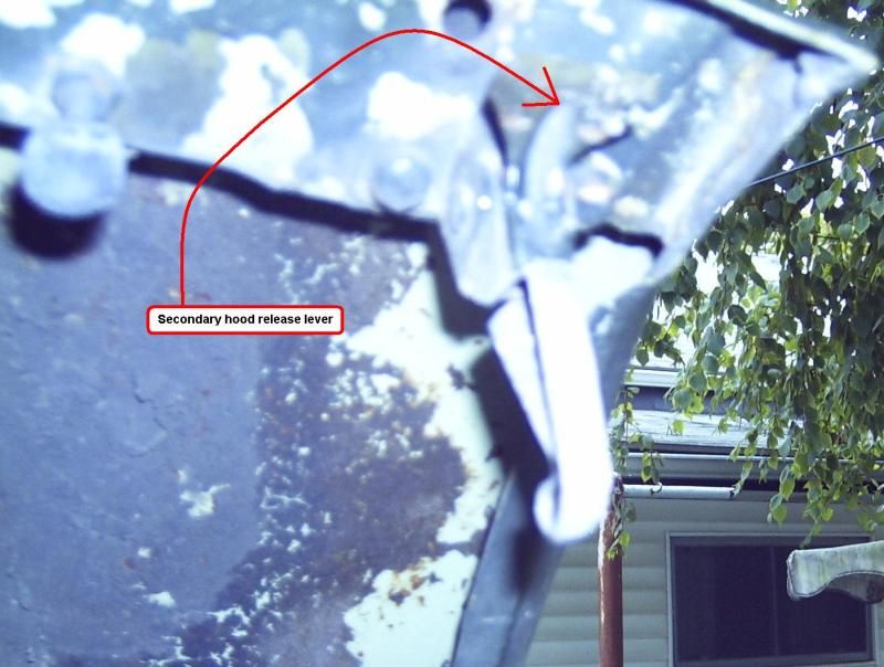 Picture 5: Take pictures before you start, special attention to throttle linkages, brackets, and vacuum routing. 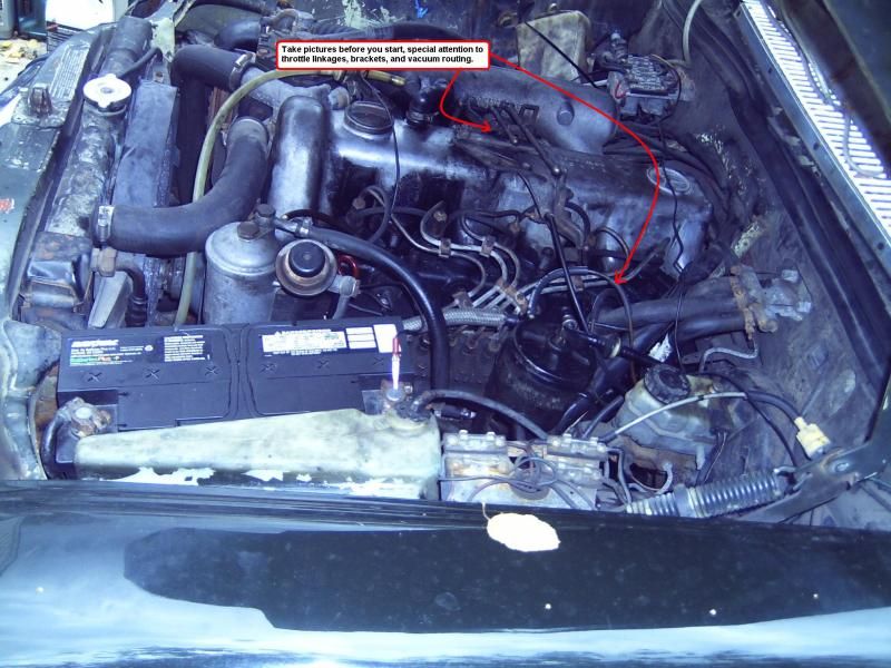 Picture 6: Disconnect the vacuum supply line from the brake booster. (to avoid damage). 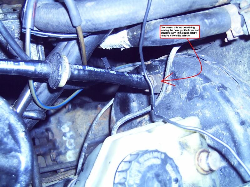 Picture 7: Remove the throttle link plate from driver side top center of the valve cover, disconnecting the linkage. (for better access).  Picture 8: Warning; If for any reason this bracket is installed “up side down” the transmission shift throttling rods will not reach the accelerator linkage. 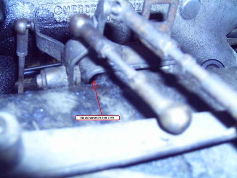 Picture 9 - 12: Remove the steel injector lines.  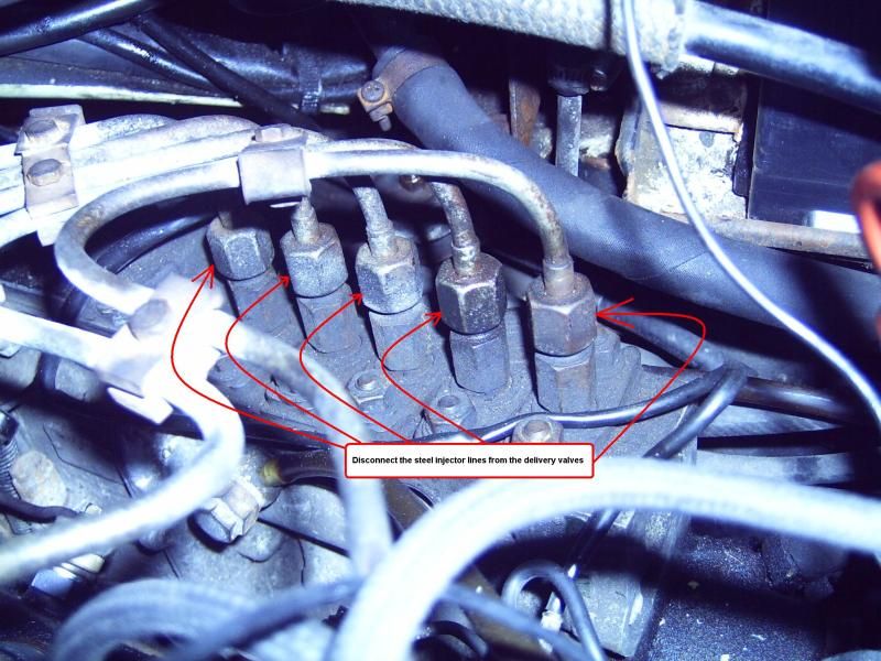   Picture 13: Cover the delivery valve ports. 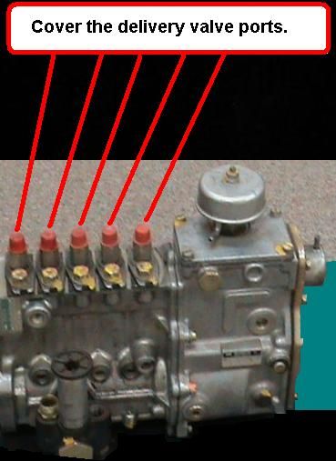 Picture 14: Cover the injector ports. 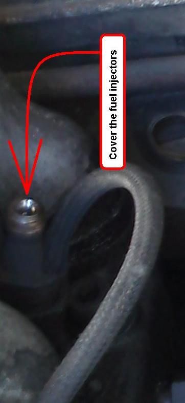 Picture 15: Remove the heater return line from the cylinder head and heater valve, capping the cylinder head fitting. (for better access).  Picture 16: Remove the vacuum line from the shutoff box. 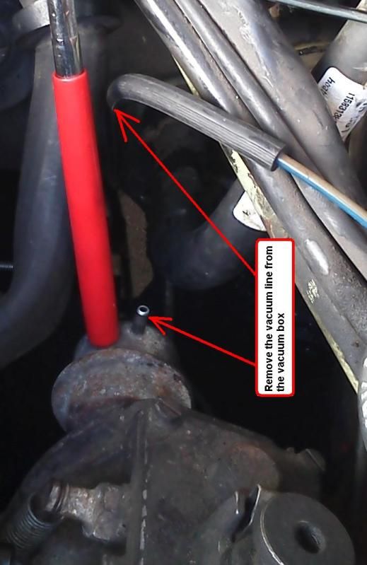 Picture 17: Place a drain pan "centered" under the rear of the injection pump, to prevent this mess.  Picture 18: Remove the six flat blade screws retaining the injection pump rear cover plate. 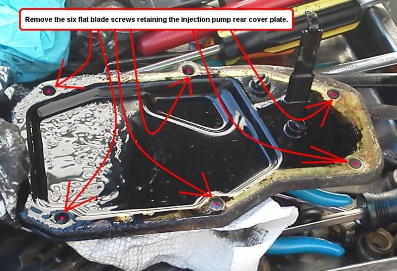 Picture 19: Rap the top edge of injection pump rear cover plate with the handle of a large screwdriver, hard enough to separate the rear cover plate from the injection pump. 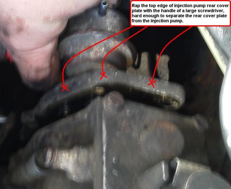 Picture 20: Gently work the injection pump rear cover plate through various angles, until the shutoff box hooked leg disengages from the injection pump rack. 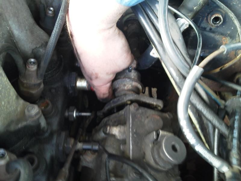 Picture 21: Remove the injection pump rear cover plate from the vehicle. 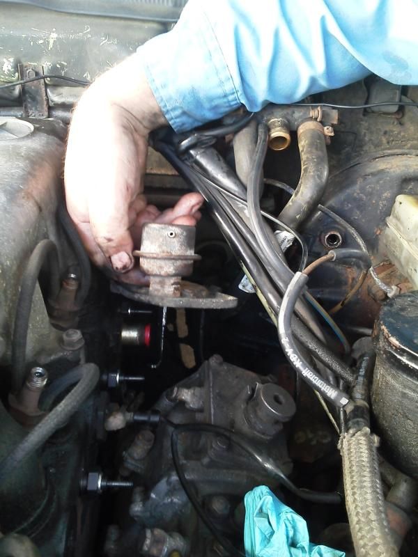 Picture 22: If the injection pump rear cover plate gasket comes off intact, it can be used as a template to cut a new one from sheet stock. Failing that, you will need to order new gaskets. 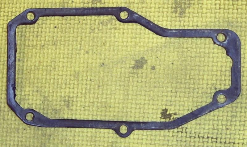 Picture 23: Remove the two flat blade screws on the inside of the cover plate, retaining the shutoff box. 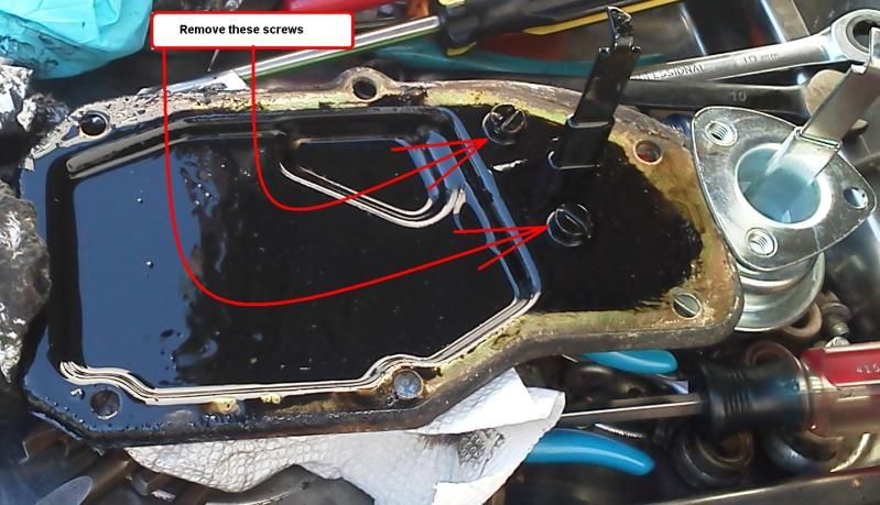 Picture 24-27: Remove the shutoff box from the cover plate. 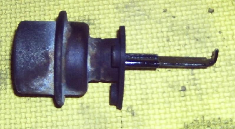 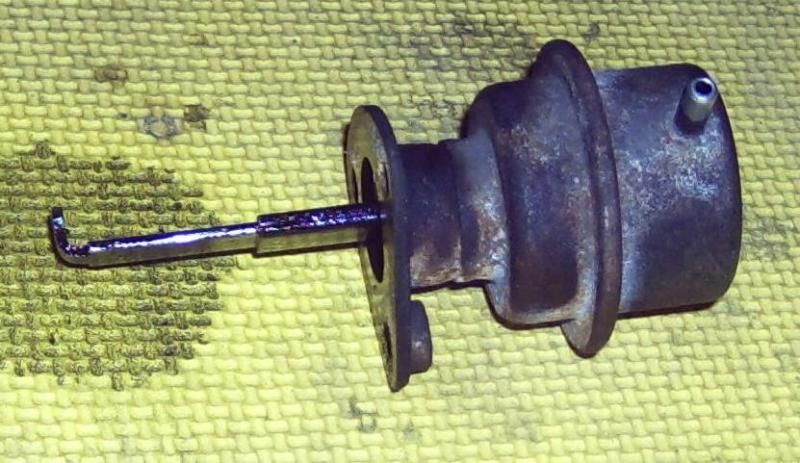 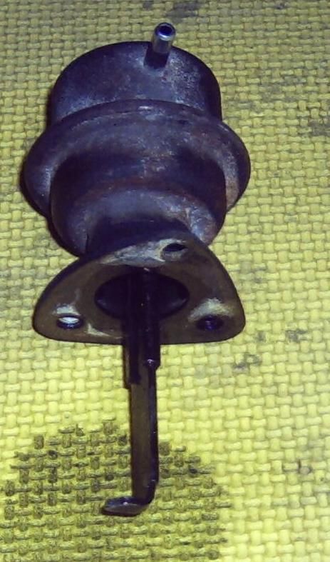 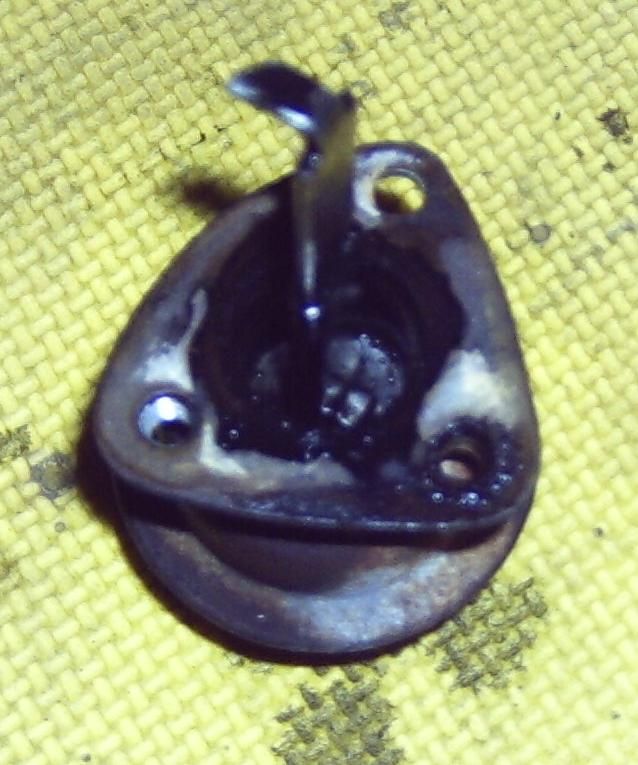
Last edited by whunter; 06-06-2013 at 12:29 AM.
|
|
#3
09-30-2012, 05:21 PM
|
||||
|
||||
|
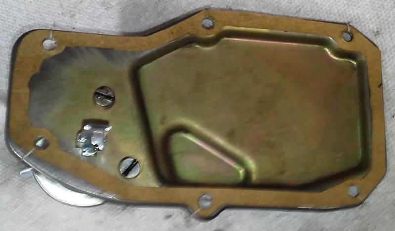
Picture 28: Remove all trace of old gasket from the inside and outside of the cover plate.
 Picture 29: Install the new shutoff box with a new gasket onto the cover plate. 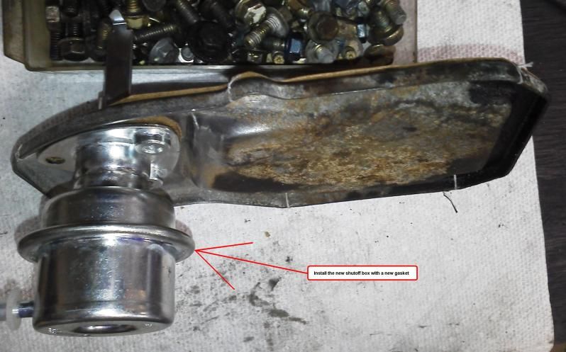 Picture 30: Install and tighten the two flat blade screws on the inside of the cover plate, retaining the shutoff box. 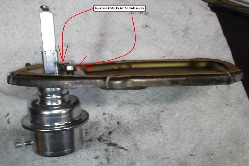 Picture 31: Use dental floss or sewing thread to install - tie the new injection pump gasket to the cover. (It simplifies installation). 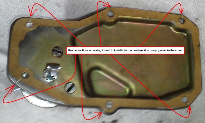 Picture 32: Install the injection pump rear cover plate to the vehicle. Picture 33: Gently work the injection pump rear cover plate through various angles, until the shutoff box hooked leg engages the injection pump rack. Note: When it catches, you can gently pull the plate assembly to the rear of vehicle and feel the rack spring resistance - return. Warning: If the shutoff box fails to engage the rack correctly, it can jam the injection rack at full throttle. Picture 34: Install and tighten the six flat blade screws into the injection pump rear cover plate. 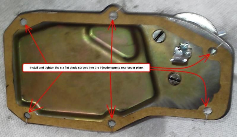 Picture 35: Remove the 19 MM plug from the top of the injection pump. 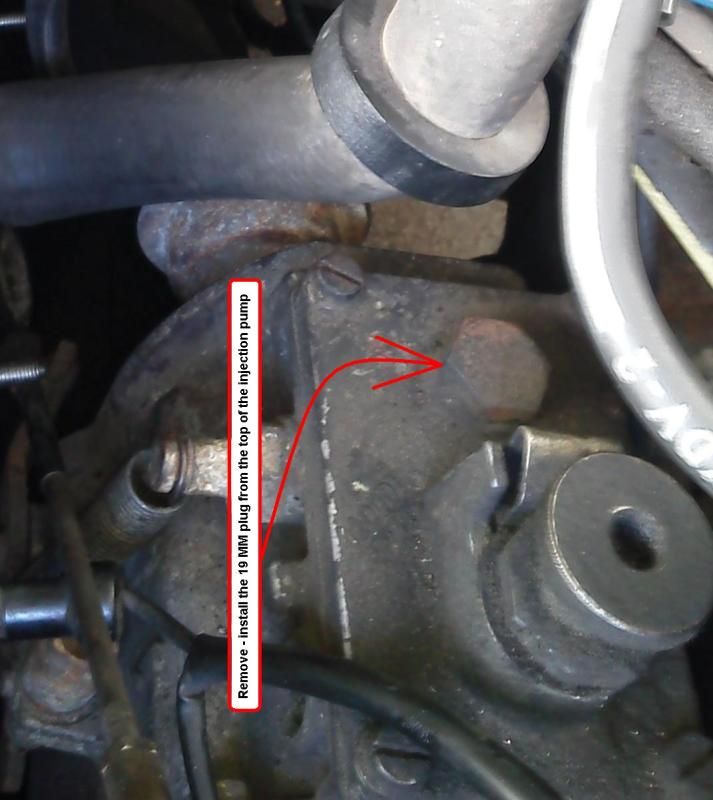 Picture 36: Add one pint of fresh engine oil.  Picture 37: Install the 19 MM plug into the top of the injection pump. Picture 38: Remove the drain pan "centered" under the rear of the injection pump. Picture 39: Install the heater return line from the cylinder head and heater valve, removing the cap from the cylinder head fitting. 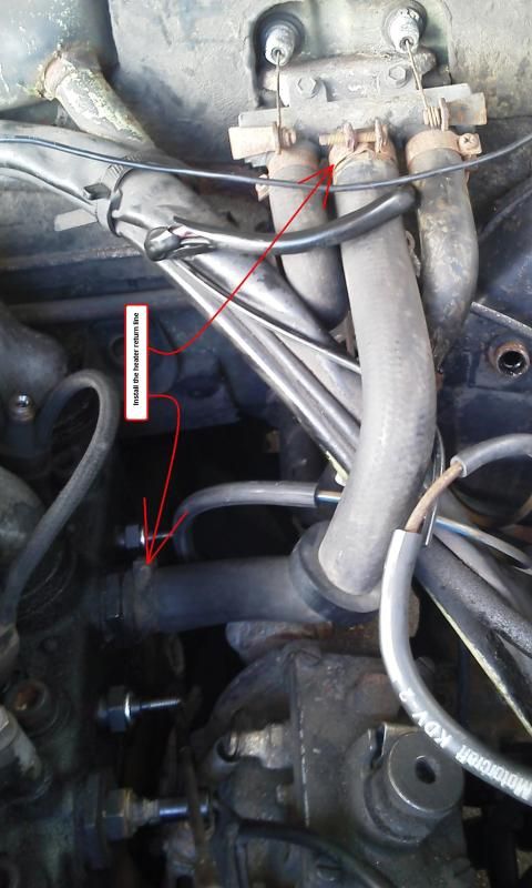 Picture 40: Install the vacuum line onto the shutoff box. 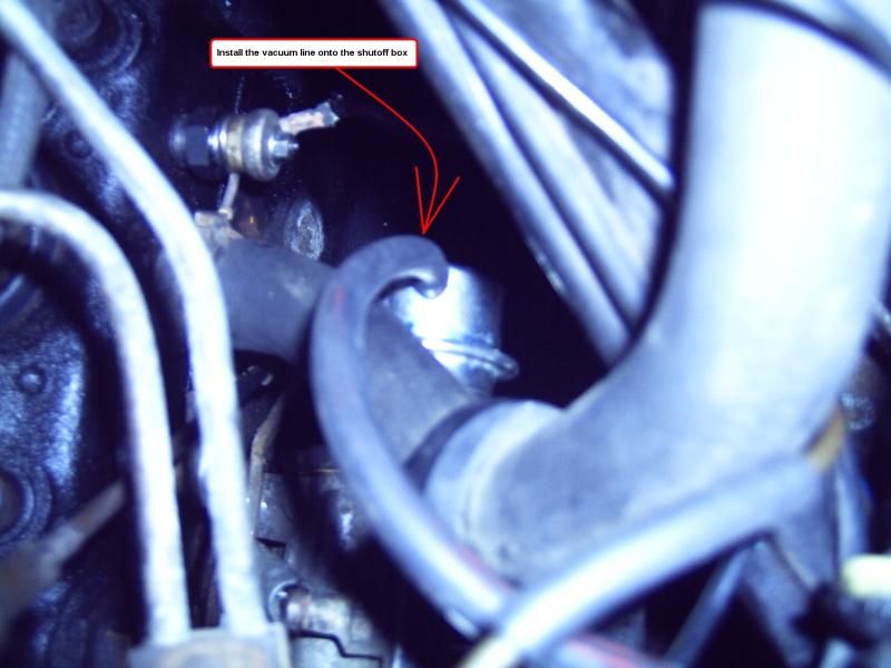 Picture 41: Remove all covers from the delivery valve ports and injector ports. 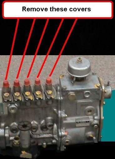  Picture 42: Install the steel injector lines.  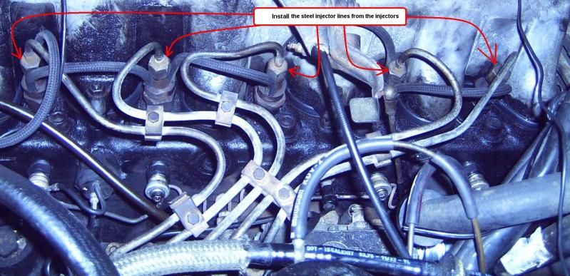  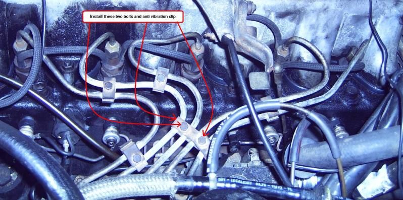 Picture 43: Install the throttle link plate onto driver side top center of the valve cover, reconnecting the linkage rods. 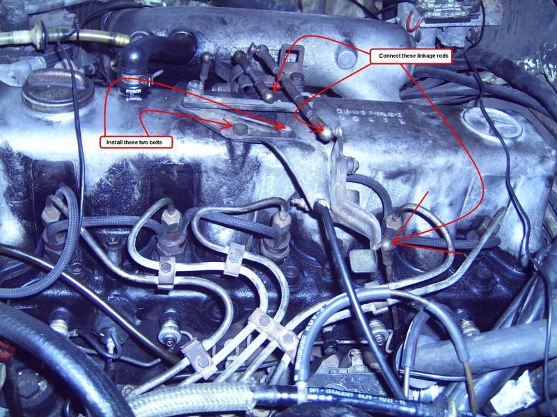 Picture 44: Install the vacuum supply line onto the brake booster. 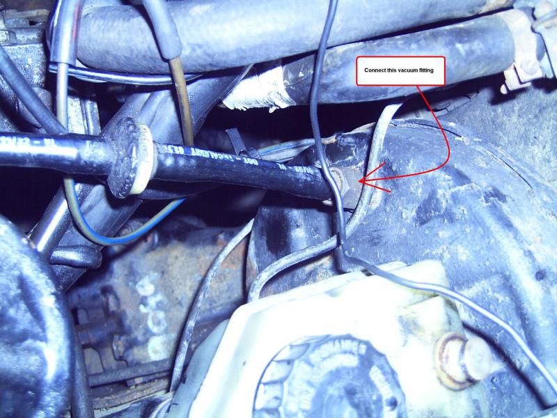 Picture 44: Here is the new shutoff box installed. 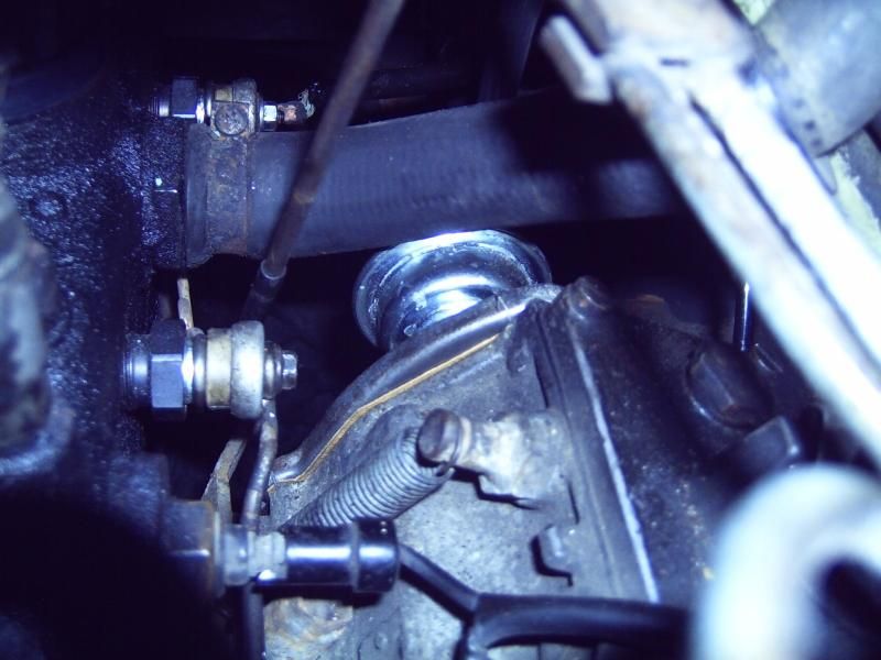 Top off the coolant level, and you are ready to test your repair. .
__________________
ASE Master Mechanic asemastermechanic@juno.com Prototype R&D/testing: Thermal & Aerodynamic System Engineering (TASE) Senior vehicle instrumentation technician. Noise Vibration and Harshness (NVH). Dynamometer. Heat exchanger durability. HV-A/C Climate Control. Vehicle build. Fleet Durability Technical Quality Auditor. Automotive Technical Writer 1985 300SD 1983 300D 1984 190D 2003 Volvo V70 2002 Honda Civic https://www.boldegoist.com/
|
|
#4
01-09-2013, 06:13 PM
|
||||
|
||||
|
Related data
Last edited by whunter; 03-01-2013 at 03:09 PM.
|
|
#5
01-10-2013, 01:55 PM
|
||||
|
||||
|
I'm glad to see that even the best of us sometimes have trouble putting the drip tray under the engine!
Great DIY Roy.
__________________
1992 W201 190E 1.8 171,000 km - Daily driver 1981 W123 300D ~ 100,000 miles / 160,000 km - project car stripped to the bone 1965 Land Rover Series 2a Station Wagon CIS recovery therapy! 1961 Volvo PV544 Bare metal rat rod-ish thing I'm here to chat about cars and to help others - I'm not here "to always be right" like an internet warrior  Don't leave that there - I'll take it to bits!
|
|
#6
03-02-2013, 09:14 AM
|
|||
|
|||
|
nice write up thanks. I was trying to figure out where the external shutoff actuator was. Nice to know where it is now, not like the turbo motors plastic one. Do you have to manually fill the IP? I thought it would fill itself from engine oil. I had my engine sitting on its end with the crankshaft up in the air for a long time while I fit the jeep transmission. Now that it is in the jeep. I thought I could just crank the engine to fill the IP. If you overfill the IP will it drain to the crankcase??
thanks
|
|
#7
03-02-2013, 06:15 PM
|
|||
|
|||
|
Good advice about being carefull about having the shut off installed correctly so that the engine doesn't free run. You won't be able to shut the engin down and it will run at full RPM!
One way you can prevent this from ever hapening is to remove the air filter and have a block ready to choke off the in coming air which will stall the engine. You can never be too carefull.........
|
|
#8
03-03-2013, 08:16 AM
|
|||
|
|||
|
It will probably run faster than full RPM, as the governor cannot pull the rack back to decrease the amount of fuel. If you are not fast enough to stop the engine, it will lead to engine damage and an expensive rebuilt or a heap of cheap scrap iron. The only way to stop the engine in this case is to disconnect the fuel supply or the air supply. The air supply cannot be stopped with your hand.
|
|
| Bookmarks |
| Thread Tools | |
| Display Modes | |
|
|


 Linear Mode


