

|
|
|
|
|
|
#1
 03-18-2007, 12:11 AM
|
||||
|
||||
|
603 harmonic balancer timing mark specification?
Hi all!
 I am getting ready to reset the timing mark on the 87 300D. Reading through the timing mark setting procedure in the tech manual, I found that is says to find TDC using a dial indicator tool through the #1 injetor port, than travel past TDC to obtain a deflection of 3.22mm which equates to 20deg ATDC. This puts the crank sensor for the RIV tool dead center in the middle of the circle where the RIV tool mounts. Does this mean that the injection pump timing is then set to 20 ATDC, if that is the setting for the RIV tool? I have searched through the forum and everyone has said that the pump should be timed to 14 deg ATDC. Can anyone help me make sense of this?  Thanks
__________________
Dean 
|
|
#2
03-18-2007, 03:05 AM
|
||||
|
||||
|
The RIV is set at 14 to 15 degrees +/- ATDC. Brian has a great description on setting the IP here:
http://www.peachparts.com/shopforum/showpost.php?p=1033162&postcount=6 I believe the theory of setting to 15 degrees is that it wears in to 14 degrees, not positive about that. One degree off will not make a lot of difference anyway. Presume your chain hasn't worn significantly? The method using the dial indicator takes mechanical wear on the cam and timing chain into account. The RIV tool is extremely accurate and you have to turn the IP (or the crank pulley if your using that method) ever so slightly (teeny weeny little bits!) to get the lamp to go from A to B. It beats the drip method I've used on the 617 which is very good but the 603 is a different engine.
__________________
'95 E320 Wagon my favorite road car. '99 E300D wolf in sheeps body, '87 300D Sportline suspension, '79 300TD w/ 617.952 engine at 367,750 and counting! Last edited by dieseldiehard; 03-20-2007 at 11:50 AM.
|
|
#3
03-18-2007, 03:18 AM
|
||||
|
||||
|
RIV timing method
Using the search tool I found a copy of the factory procedure:
http://ken.kdharris.net/kdhbenz/07-1-111.pdf
__________________
'95 E320 Wagon my favorite road car. '99 E300D wolf in sheeps body, '87 300D Sportline suspension, '79 300TD w/ 617.952 engine at 367,750 and counting!
|
|
#4
03-18-2007, 12:43 PM
|
||||
|
||||
|
Here is the procedure I am working from to set the TDC indicator:
http://webpages.charter.net/deanot442/03-345.pdf This is where it is telling me to set the indicator to 20 deg ATDC.
__________________
Dean
|
|
#5
03-20-2007, 03:57 AM
|
|||
|
|||
|
Dean,
what do you want to do? IP timing: by RIV method set to 15 deg ATDC. Your explanation describes the setting of the TDC sensor in the balancer, which is 20 deg ATDC. This set up is only made in case the engine was disassembled to adjust the sensor to the correct crankshaft position. Only for dynamic timing this TDC sensor is used. Tom
|
|
#6
03-20-2007, 05:47 AM
|
||||
|
||||
|
Tom,
I am trying to set the TDC indicator because the indicator was removed due to an earlier tear-down (cracked head, subsequent timing cover leak, timing chain replacement.....) I am setting the TDC indicator to be able to use the RIV tool, to set the rest of the timing. My thought was that, the sensor of the RIV tool that gets placed on the balancer, therefore ends up being placed at 20deg ATDC by the procedure  I have referenced above. Am I correct? (I realize that the procedure above is not for setting IP timing but it does set the reference point of the crank for the RIV) I have referenced above. Am I correct? (I realize that the procedure above is not for setting IP timing but it does set the reference point of the crank for the RIV)see procedure at: http://webpages.charter.net/deanot442/riv%20timing%20mehod.pdf Then the other part of the RIV tool goes into the IP and senses on its internal timing mark. So if that were the case wouldnt the IP then be set for 20 instead of 14deg ATDC, or is there some type of compensation built into the RIV tool that adjusts for the difference? Or am I just waaaaaay off on my thought process????? The way I am thinking is that the sensor holder at the balancer should be set at 14deg ATDC to match the IP setting.
__________________
Dean Last edited by deanot442; 03-20-2007 at 06:00 AM. Reason: adding riv timing procedure from cd manual
|
|
#7
03-20-2007, 11:09 AM
|
|||
|
|||
|
Dean,
o.k. now it is a little bit clearer for me. The 15 deg ATDC for the RIV method is just a number for timing, depending on the inner notch of the IP. It is just an abstract position for the 24 +- deg BTDC of crankshaft position when delivery should start. The degs on the balancer is the master (physically correct position of the crankshaft). The TDC sensor pin on the balancer is placed just somewhere. Now according the adjustment of the TDC sensor procedure the crank shaft has to be at 20 deg ATDC to have pin and sensor aligned. When the notch in the IP is present (for the RI) it is start of delivery (static RIV method). The spec speaks of indirect start of delivery when a tester is used. Different testers like AVL, SUN, Bosch or Hartmann have not the same settings in the spec. So the testers have some internal differences. I.e. I have to set my 617.95x to 21 deg BTDC using clamp and lamp of the AVL. Approx. 5 deg off compared to the drip method. Using clamp and TDC sensor (diagnostic socket) the AVL shows me the 26 deg in the display. Summary: Cant answer your question. I think it is like that but dont know why. Tom
|
|
#8
03-20-2007, 03:02 PM
|
||||
|
||||
|
The TDC pointer on the front of the engine has a 3° adjustment range. Generally it will end up being in the middle, if you set it with a dial gauge. I set mine with the cylinder head off, using a dial gauge on the piston crown to determine TDC. The 20° number you mention has NOTHING to do with pump timing... that is to allow quick setting of the TDC indicator using a special tool. None of this is really necessary though. If you have the head removed, it's nice to verify the pointer is accurate, but otherwise just leave it alone (or set it in the middle, if it's been disturbed.)
For the RIV tool, which I assume you mean the static setting using the A-B light box, you set it to 14° ATDC. As the timing chain wears, the setting will become retarded over time (15, 16, 17, etc) but this generally takes decades and 100's of k's of miles. Forget the 24° (BTDC) number, that's for the wet methods. If you set it at 15° ATDC with the RIV (dry) method, then checked that setting with a wet method, it should read 24° BTDC. Same actual setting, different methods of measuring, each with a different reference point. I think you may be making it all more complicated than it really is, lol... 
|
|
#9
03-20-2007, 10:00 PM
|
||||
|
||||
|
Tom, Dave.
Thanks for taking the time to reply. You both have been very helpfull. Dave I see your point about the quick set tool. I think I was getting sidetracked by the timing device called out in the procedure on my cd (see attached photos) it shows 2 sensors being used together one at the balancer and one in the pump tied together in a test box. I thought the more commonly used RIV tool used the same method, but thats where I was incorrect
__________________
Dean
|
|
#10
03-21-2007, 09:32 AM
|
||||
|
||||
|
Quote:
The difference is that the factory setup (shown in your photo of the FSM) plugs into the pump's RIV port, sensing a tab on the governor flywheel. The aftermarket quick-connect setups use a piezo sensor that clamps on to the #1 fuel line. You'll get different readings from the two methods. The more commonly used tool is the static "A-B light box", which plugs into the RIV hole in the side of the pump, but requires you to use your eyeballs to read the balancer. I have this tool, it works great, but doesn't allow checking the timing with the engine running (and I can live with that.)  This tool has gone up in price, I think it's closer to $300 now: 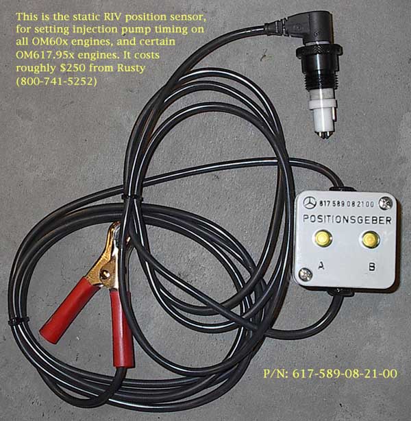
|
 |
| Bookmarks |
|
|


 Linear Mode


