

|
|
|
|
|
|
#16
 05-29-2011, 03:43 AM
|
||||
|
||||
|
Quote:
(I can post proof if you want)
__________________
1992 W201 190E 1.8 171,000 km - Daily driver 1981 W123 300D ~ 100,000 miles / 160,000 km - project car stripped to the bone 1965 Land Rover Series 2a Station Wagon CIS recovery therapy! 1961 Volvo PV544 Bare metal rat rod-ish thing I'm here to chat about cars and to help others - I'm not here "to always be right" like an internet warrior 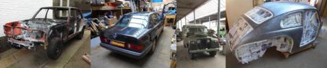 Don't leave that there - I'll take it to bits! 
|
|
#17
05-29-2011, 05:16 AM
|
||||
|
||||
|
Haha! I believe you I believe you!
Every model change the wires grow exponentially. 
__________________
 85 190E 2.3(SOLD) 86 230E (-->300D) sold 87 300D (-->300TD) sold 68 250S w/ a 615 and manual tranny (RIP) 87 300TD (SOLD) 95 S280 "The KRAKEN" (Turbo 2.9 602 transplant) traded 86 190E 2.3... current project
|
|
#18
05-29-2011, 07:33 PM
|
|||
|
|||
|
Quote:
Either way it does not look like I can easily access that from under the dash or through the glove box.
|
|
#19
05-30-2011, 12:36 AM
|
||||
|
||||
|
it's the opening the red arrow is pointing to... it actually goes all the way across to the other end. Nope, you absolutely cannot access it through the glovebox or anywhere for that matter. Removal of the dash is your only option, and even then the vacuum pods will get in the way probably. I've since removed all of those.
btw, i'm getting an underdash unit later today, i'll know later if it'll fit without much effort. I'm thinking it will.  (hoping actually) (hoping actually)
__________________
85 190E 2.3(SOLD) 86 230E (-->300D) sold 87 300D (-->300TD) sold 68 250S w/ a 615 and manual tranny (RIP) 87 300TD (SOLD) 95 S280 "The KRAKEN" (Turbo 2.9 602 transplant) traded 86 190E 2.3... current project
|
|
#20
05-30-2011, 09:20 AM
|
||||
|
||||
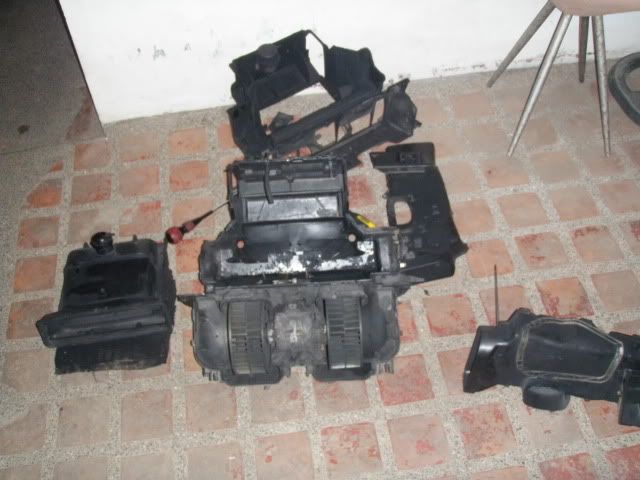 go back to stock?...or..... 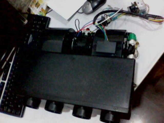 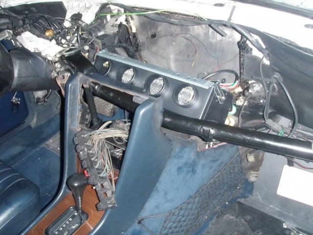 lots of space without the original airbox!!! it even cleared the tunnel carpeting!
__________________
85 190E 2.3(SOLD) 86 230E (-->300D) sold 87 300D (-->300TD) sold 68 250S w/ a 615 and manual tranny (RIP) 87 300TD (SOLD) 95 S280 "The KRAKEN" (Turbo 2.9 602 transplant) traded 86 190E 2.3... current project
|
|
#21
08-08-2011, 01:44 AM
|
||||
|
||||
|
I'm finally done with the entire install... I just recently finished re-wiring the pushbutton control unit in place of the rotary switch that came with the evap/bower kit.
I wired 6 relays to the CCU so I can now control the ac through the buttons. the 3 fan speed buttons now function as 1,2,3 fan speeds. 3 more buttons are used for off, econ, normal modes. It involved hacking the CCU pcb.Cleaned everything inside the CCU now the markings are brandnew bright.
__________________
85 190E 2.3(SOLD) 86 230E (-->300D) sold 87 300D (-->300TD) sold 68 250S w/ a 615 and manual tranny (RIP) 87 300TD (SOLD) 95 S280 "The KRAKEN" (Turbo 2.9 602 transplant) traded 86 190E 2.3... current project
|
|
#23
08-08-2011, 03:31 PM
|
|||
|
|||
|
Quote:
|
|
#24
08-08-2011, 11:34 PM
|
||||
|
||||
|
Will upload pics... but here's a brief description of the CCU hack:
-Disassemble the CCU unit -cut/disconnect the ribbon cables of both the fan speed switches and the illumination unit (you'll know it when you see it) -identify the PCB paths of the 3 buttons that you wish to utilize (the horizontal row of buttons) -scratch them out using the tip of a small screwdriver, make sure there's no continuity when you're done -identify which "prongs" on the individual switches closes the circuit for each switch (in my case its the rear most prongs and the middle prongs) use a multitester to be sure ---------------------------- I decided on using 3 of the horizontal buttons for turning on the AC normally, fans only and off. I also decided on using the 3 fan speed buttons (vertical ones) as 1,2,3 fan speeds I used a total of 6 Relays. 3 relays go to each fan speed switch 2 relays go to the "normal" on button 1 relay goes to the "econ" button You will basically make 2 relay groups. The "MAIN" relays, connected to the "main" buttons and the "FAN" relays, connected to the 3 fan speed buttons The main relays have a common ground, so I bundled their ground 'trigger' wires together. They also have the same 'supply' trigger wires so bundle I them together as well... The ROLE of 2 of the MAIN relays, when TRIGGERED just supplies a POSITIVE current to the "FAN" relays' 'triger' supply lines... (x3) (NOTE: I used low current negative and positive connections to trigger the relays) The "FAN" relays just closes the loop for the high current lines which are connected to the blower resistor unit. BTW... to make it simpler, I just bundled ALL the relays' 'trigger' grounds together. Why a 3rd relay for the MAIN group? I wasn't sure how much current the compressor clutch draws so I just isolated its circuit by using its own relay... attach that relay to the "normal" button... but use the high current line instead of the low current trigger lines to close the compressor clutch loop. In summary, when the OFF button is depressed, none of the relays are energized when the ECON button is depressed, it energizes its RELAY which in turn supplies and energizes another relay (whichever fan speed button is depressed), which in turn closes a high current loop powering the blower. when the NORMAL button is depressed, it energizes 2 RELAYS, one similar in function to the one above...AND the other, simultaneously, closes the loop for the compressor clutch. (I could do away with the compressor clutch relay IF the clutch didn't require much current... but that I have no idea how to compute) I'm not an auto electrician, so I do not know if used the correct terms, but I made sure I used the correct wires/connections so as to isolate high and low current requirements... thus the use or overuse of RELAYS. i know, pictures!!! btw... the BLOWER/EVAP unit I bought came with e ROTARY switch that has 5 wires coming OFF it, 3 are for the 3 fan speeds, 1 main supply line and 1 clutch trigger wire(connected to a rotary thermostat). This is where I ended up connecting wires to. How do I control the temp then? Since I live in a tropical country, I opted to just set the temp on cool all the time, and just HID the thermostat behind the CCU.... Almost forgot... just solder 2 long wires for the light bulb unit and splice that to something which is triggered by ILLUMINATION..
__________________
85 190E 2.3(SOLD) 86 230E (-->300D) sold 87 300D (-->300TD) sold 68 250S w/ a 615 and manual tranny (RIP) 87 300TD (SOLD) 95 S280 "The KRAKEN" (Turbo 2.9 602 transplant) traded 86 190E 2.3... current project
|
|
#25
08-08-2011, 11:58 PM
|
||||
|
||||
|
You realize you'll have to redo all that when you get your hands on a Euro AC control panel, right?
Sixto 87 300D
|
|
#26
08-09-2011, 12:11 AM
|
||||
|
||||
|
hahaha, I could've gotten a cheap set but I opted to stay "stock"... hahaha, after hacking the hell out of the car I have the nerve to say "stock"...
__________________
85 190E 2.3(SOLD) 86 230E (-->300D) sold 87 300D (-->300TD) sold 68 250S w/ a 615 and manual tranny (RIP) 87 300TD (SOLD) 95 S280 "The KRAKEN" (Turbo 2.9 602 transplant) traded 86 190E 2.3... current project
|
|
#27
08-09-2011, 02:12 AM
|
||||
|
||||
|
Quote:
__________________
08 R320 CDI current Past 95 E420 87 300D Turbo 5spd 90 300TE 83 300SD 85 300TD 92 400E 85 190D
|
|
#28
08-09-2011, 02:15 AM
|
||||
|
||||
|
is 6-8 amps safe for switches? is it safe for me to supply the clutch with the 'positive' wire that's also supplying my 2 MAIN relays?
__________________
85 190E 2.3(SOLD) 86 230E (-->300D) sold 87 300D (-->300TD) sold 68 250S w/ a 615 and manual tranny (RIP) 87 300TD (SOLD) 95 S280 "The KRAKEN" (Turbo 2.9 602 transplant) traded 86 190E 2.3... current project
|
|
#29
08-09-2011, 11:54 AM
|
||||
|
||||
|
I am having a hard time "following" your circuit. I need to see a schematic to totally understand what your doing. I have the basic concept understood. But 6-8 amps would be too much current to run through the PBU switches. You would surely need another relay for the clutch on the compressor.
__________________
08 R320 CDI current Past 95 E420 87 300D Turbo 5spd 90 300TE 83 300SD 85 300TD 92 400E 85 190D
|
|
#30
08-10-2011, 01:56 AM
|
||||
|
||||
|
I indeed have a separate relay for the compressor clutch installed right now.
I don't know the first thing about writng a 'proper' schematic. 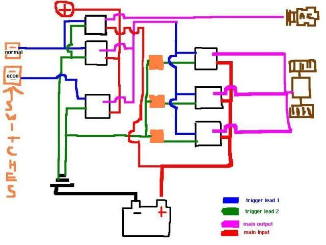
__________________
85 190E 2.3(SOLD) 86 230E (-->300D) sold 87 300D (-->300TD) sold 68 250S w/ a 615 and manual tranny (RIP) 87 300TD (SOLD) 95 S280 "The KRAKEN" (Turbo 2.9 602 transplant) traded 86 190E 2.3... current project Last edited by locry; 08-10-2011 at 02:10 AM.
|
 |
| Bookmarks |
|
|


 .
.


 Linear Mode


