

|
|
|
|
|
|
#16
 01-18-2021, 03:12 PM
|
||||
|
||||
|
The pin locations can be micd out. Its routine but a pain. Finding the right pins is another chore.
I started wondering how the pros actually do this. It turns out there are a class of interface ic called a variable reluctance sensor interface. This is used upstream of the microcontroller as to not burden the processor with peak detection and sampling chores. On semi has the NVC1124. This is very promising. Cheap and easy to use with few passives. Maxim has the MAX9924 and others. These are a little more complicated to configure but their different modes look they have good noise immunity. Theres the TI LM1815 as in the car. Looks straightforward to replicate the old circuit and make a board. Does anyone even want one?
__________________
79 300TD Old Smokey AKA The Mistake (SOLD) 82 240D stick shift 335k miles (SOLD) 82 300SD 300k miles 85 300D Turbodiesel 170k miles 
|
|
#17
01-18-2021, 03:20 PM
|
||||
|
||||
|
Since the LM1815 is still available (and cheap) it's mind-blowing to me that nobody has bothered to simply reverse-engineer the original MB amp and make a modern one with modern components.
__________________
Current stable: 1995 E320 149K (Nancy) 1983 500SL 120K (SLoL) Black Sheep: 1985 524TD 167K (TotalDumpster) Gone but not forgotten: 1986 300SDL (RIP) 1991 350SD 1991 560SEL 1990 560SEL 1986 500SEL Euro (Rusted to nothing at 47K!)
|
|
#18
01-18-2021, 04:48 PM
|
||||
|
||||
|
Quote:
Having said that, if someone did come up with a drop in or "use your original pins" replacement or provided the sketch and board files, I'd consider it. Especially if it did the sweep the gauge trick or some other cool but not really necessary party trick and wasn't too expensive. Michael
__________________
Usta haves '69 250/8, '76 280C, 1971 250C 114.023, 1976 450SEL 116.033 Current have, 1983 300SD 126.120
|
|
#19
01-24-2021, 09:44 PM
|
||||
|
||||
|
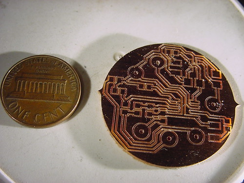
I’m probably going to regret starting this but I couldn’t stay away. Covid lockdown is so boring. Here is my first cut at a tach amp. I’m waiting for parts to arrive. Then I’ll assemble and test. I have a bad habit of saying I’m going to do things and then disappearing. Hopefully I’ll be able to make this work.
__________________
79 300TD Old Smokey AKA The Mistake (SOLD) 82 240D stick shift 335k miles (SOLD) 82 300SD 300k miles 85 300D Turbodiesel 170k miles
|
|
#20
01-24-2021, 09:46 PM
|
||||
|
||||
|
I'll be following this!
|
|
#21
01-24-2021, 09:47 PM
|
||||
|
||||
|
Quote:
__________________

|
|
#22
01-24-2021, 10:34 PM
|
||||
|
||||
|
Looks like someone got a CNC router for Christmas!
I'd probably get one too. Either a bare board plus PIC or a complete unit. I thought my issue was the pickup but it turns out I used a scope with too low a resolution. The good scope showed the pickup working but the output of the amp at 2.7 volts peak, not 5. I didn't bother checking VCC at the chip as I had other projects in the works at the time. Michael
__________________
Usta haves '69 250/8, '76 280C, 1971 250C 114.023, 1976 450SEL 116.033 Current have, 1983 300SD 126.120
|
|
#23
01-25-2021, 10:24 AM
|
||||
|
||||
|
Michael,
2.7v at the output sounds odd. The LM1815 has an open collector output. So it drags something upstream down to zero from a nominal supplied voltage like 5v. Did you measure this with the tach hooked up? Basically it needs a weak 5V source to pull down. Looking at the schematics in this thread the 5V source comes from the tach, not the amp. I don’t think it’ll make a nice waveform if it’s just floating. Edit- oops spoke too soon again. Looks, the output is open collector but it is wired up to take Vcc pulled through a 22k resistor. Wonder how this works out to 5v...but you’re right you probably should check Vcc.
__________________
79 300TD Old Smokey AKA The Mistake (SOLD) 82 240D stick shift 335k miles (SOLD) 82 300SD 300k miles 85 300D Turbodiesel 170k miles Last edited by ykobayashi; 01-25-2021 at 10:43 AM.
|
|
#24
01-25-2021, 11:59 AM
|
|||
|
|||
|
Quote:
Here is something I started playing around with the other day: https://youtu.be/Vkeyk02wt8U I'm actually shocked how simple it was to get this set up. The tach amp has for years been shrouded in mystery it seems, but its actually a very easy device to emulate, which in turn means with just a few components replacing it should be a breeze.
__________________
1982 300D (w123, "Grey Car") 1982 300D (w123, "Blue Car") 2001 Ford F150 "Clifford" (The Big Red Truck) 1997 Dodge Ram 2500 12V Cummins 1996 Dodge Ram 2500 12V Cummins Previous Vehicles: 1995 E300D, 1980 300SD, 1992 Buick Century, 2005 Saturn Ion
|
|
#25
01-25-2021, 12:52 PM
|
||||
|
||||
|
ykobayashi,
To be honest, I was only looking at input vs output with the biased expectation that the pickup was bad. The thing is, the new and old pickups are within 5 or 6 ohms and are just coils of wire which means mine is probably good. I was thinking the face had hit the pin and been damaged, allowing water or oil in, causing it to have reduced output. A quick check with online calculators show a 5.6V zener with a ~360 ohm resistance in series should produce ~5 VDC at ~10mA. That could explain the rather high resistance of the pull up on the output. It implies the tach has a somewhat high input impedance and does not need significant current on it's input, saving what little there is for the LM1815 which is rated 6mA max. Low input impedance could be caused by the same capacitors that kill the clock. I was going to replace the caps in the tach but it looked like a pain and it worked on the signal generator. I'm pretty sure the signal generator can push way more than 10mA, it'll drive 20V P-P into 50 ohms. I need to spend more than a quick 5 minutes checking V in, ground and VCC as well as the pickup signal and output. And distance from the face of the pickup to the pin just in case someone has messed with it. And pull the tach to change the capacitors. I don't know if this thread as been linked here, it has a very good description of how the amp works but unfortunately I've not been able to find a copy of the large version of the schematic and the small one is heavily pixelated. Also, the tach worked intermittently when we picked the car up but quit after a week or two. I do know it's not solder joints, I've resoldered the entire board. Michael
__________________
Usta haves '69 250/8, '76 280C, 1971 250C 114.023, 1976 450SEL 116.033 Current have, 1983 300SD 126.120
|
|
#26
01-25-2021, 03:08 PM
|
||||
|
||||
|
Michael-
5-6 ohms sounds too low. I measured 70 ohms/68mH on mine. Jarod - Nice work. I am not doing a MCU design. I’m too lazy. Nice work on the Arduino. If my design works you can run the TTL output into the Arduino.
__________________
79 300TD Old Smokey AKA The Mistake (SOLD) 82 240D stick shift 335k miles (SOLD) 82 300SD 300k miles 85 300D Turbodiesel 170k miles
|
|
#27
01-25-2021, 04:16 PM
|
||||
|
||||
|
ykobayashi,
5-6 ohms would be too low. What I meant was that the difference between a new pickup and the installed one is about 5 or 6 ohms. 68 and 72 Ohms? Maybe, it was a few days ago and my excuse is I'm old. The brand new one tests as 71.9 ohms and 60.5mH in series which sounds like it's pretty close to what you found with yours. I did not install the new one yet, it looked like a real pain to get at the small nut that holds the pickup to the bracket and it didn't occur to me to see if the bracket would be easier to remove till this morning. Are you working on a SMC version of the original circuit? I see a 8 pin device which implies a PIC or an op-amp. Michael PS, I too have a bad habit of saying I'll do something then not fully follow through. The Ford truck forums probably gave up on my project to connect all 3 tanks to the gas gauge (one at a time) and add solenoids to switch between them. Everything is installed, I just need to reroute 4 hoses. It's been 8 months now.
__________________
Usta haves '69 250/8, '76 280C, 1971 250C 114.023, 1976 450SEL 116.033 Current have, 1983 300SD 126.120
|
|
#28
01-25-2021, 05:03 PM
|
||||
|
||||
|
Got it. Just trying to eliminate the obvious on your car. I looked at your photo and it looks like you resoldered the board. That’s what fixed mine.
My board uses the NCV1124 from On Semi.
__________________
79 300TD Old Smokey AKA The Mistake (SOLD) 82 240D stick shift 335k miles (SOLD) 82 300SD 300k miles 85 300D Turbodiesel 170k miles
|
|
#29
01-27-2021, 10:49 AM
|
||||
|
||||
|
Jarod,
What was the range of frequencies to get the needle to sweep full scale?
__________________
79 300TD Old Smokey AKA The Mistake (SOLD) 82 240D stick shift 335k miles (SOLD) 82 300SD 300k miles 85 300D Turbodiesel 170k miles
|
|
#30
01-27-2021, 02:51 PM
|
|||
|
|||
|
Here is what I have calculated from my arduino test:
100hz = 6000rpm 83hz = 5000rpm 71hz = 4500rpm 62.5hz = 4000rpm 55.5= 3500rpm 50hz =3000rpm 45hz =2800rpm 41hz=2600rpm 38hz =2400rpm 33.3hz=2000rpm 27.7hz =1800rpm 25hz =1600rpm 20hz =1500rpm 17.8hz =1000rpm 16hz =900rpm 14hz =700rpm Some of those are rounded slightly due to how I was doing the timing of the signal, and I'm sure some tachs may be slightly different in sensitivity.
__________________
1982 300D (w123, "Grey Car") 1982 300D (w123, "Blue Car") 2001 Ford F150 "Clifford" (The Big Red Truck) 1997 Dodge Ram 2500 12V Cummins 1996 Dodge Ram 2500 12V Cummins Previous Vehicles: 1995 E300D, 1980 300SD, 1992 Buick Century, 2005 Saturn Ion
|
 |
| Bookmarks |
| Thread Tools | |
| Display Modes | |
|
|


 Linear Mode


