

|
|
|
|
|
|
|||||||
 |
|
|
LinkBack | Thread Tools | Display Modes |
|
#16
 04-10-2011, 02:06 PM
|
|||
|
|||
|
I wanted to add a little more to the thread.
I am replacing both sets of bearings. I measured the bearing and bought a tube so that i could pound it onto the flange as per the instructions in the Mercedes manual. I took one flange and put the tube on it and pounded away. I got it seated, but every time I whacked it I kept worrying that the tube might move and I would wreck the bearing. Plus, I was banging on it pretty hard and was wondering how in the world I was going to hammer the ineer bearing onto the flange while someone tried to hold the flange in place. I decided to make a press that would work like the factory tool that I would use to press on the second outer bearing and that I could use on the car for the inner bearing. Here is what I came up with. It works really well and I highly recommend putting together something like this. I only did the other outer bearing, but expect the inner bearing to work just as well. The tube I am using is too long for the inner, so I am going to cut it shorter before I do the inners.    
Last edited by whunter; 04-10-2011 at 02:23 PM. Reason: copy of post + attached pictures 
|
|
#17
04-16-2011, 01:26 PM
|
||||
|
||||
|
MB38 Professional Scan Diagnostic Car Tool New
Last edited by whunter; 06-22-2012 at 07:49 PM.
|
|
#18
05-11-2011, 04:59 PM
|
||||
|
||||
|
FUEL SENDING UNIT disassembly tool
On the bottom of the fuel sending, there is a round nut that screws onto the rod that holds the unit together. Clean the nut (favorite toothbrush) so you can see what you have. The nut is slotted, but it also has the rod protruding through the nut so a conventional screw driver won't work.
If you have a dremel, grind the outside of a small screw driver, so that its sides are parallel and will fit inside the circular bottom. Then grind out the center of the screwdriver blade so that it fits into the slot on the nut. You need to go far enough in, so that the blade is all the into the slot on the nut and the rod will fit into the ground down area without bottoming. DO NOT FORCE THE SCREW DRIVER IN ! Cut it so that it easily fits, and turn counter-clockwise. Careful of the three very thin wires running legnthwise in the tube. Clean all inside and out very carefully, and then reassemble when dry. If you forgot to look at the bottom two peices and how they went together, they really only go together again in EASY fashion, if they are in correct order and facing the right way. Screw all together.
|
|
#19
05-11-2011, 05:31 PM
|
||||
|
||||
|
Drawing
Quote:
|
|
#20
05-12-2011, 04:03 AM
|
||||
|
||||
|
FYI
Commonly found in "security bit sets" <= internet search phrase => http://www.harborfreight.com/100-piece-security-bit-set-91310.html
__________________
1992 W201 190E 1.8 171,000 km - Daily driver 1981 W123 300D ~ 100,000 miles / 160,000 km - project car stripped to the bone 1965 Land Rover Series 2a Station Wagon CIS recovery therapy! 1961 Volvo PV544 Bare metal rat rod-ish thing I'm here to chat about cars and to help others - I'm not here "to always be right" like an internet warrior 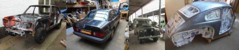 Don't leave that there - I'll take it to bits!
|
|
#21
07-10-2011, 01:10 AM
|
||||
|
||||
|
Home-made $15 W124 LCA Bushing Tool
Sixto has written an excellent guide for replacing W124 LCA (Lower Control Arm) bushings here. I was replacing the Lower Control Arms on my '87 300D Turbo (W124, OM603) because one of the inner bushings was bad. I discovered that I also needed to replace the outer bushings, which are pressed into the wheel carrier. Unfortunately, I did not have the expensive tool needed to remove the old bushings and install the new ones and decided to build my own tool. This tool, or something similar, probably will work on other models of Mercedes. Sixto's thread has excellent pictures of the commercial tool. I made a trip to the local hardware store and managed to make my own tool from three galvanized steel pipe fittings and several 1/2 inch bolts, nuts, and washers. The total parts cost was about US$15. Parts List with cross-reference to part names used by Sixto to describe the commercial tool A. 1 each 1-1/2" x 2" nipple (dual-purpose "removal receiver" and "installation receiver" Note: see text) B. 1 each 1-1/4" x 2" nipple ("installation drift") C. 1 each 3/4" coupling ("removal drift") D. 5 each 1/2" bolts in sizes from 5 to 7 inches (Because the bolts at the hardware store were not threaded all the way, I had to change to shorter bolts as the bushing gradually was pushed out or in. With a bolt threaded all the way, only one is needed.) E. 2 each 1/2" nuts (one to use and one to lose) F. Assorted 1/2", 5/8" and 3/4" washers (they bend if you use only one) The head of the bolt and the nut both take a 3/4" wrench. I used a 1/2" ratchet and a deep 3/4" socket on the nut plus a 3/4" combination wrench to counter-hold the head of the bolt. I put some anti-seize on the threads of the bolt(s) to reduce friction. These were normal coarse-thread bolts (13 threads per inch, I think). To remove a bushing from the wheel carrier you need parts "A" and "C" plus two or three of the bolts, some washers, and a nut. In the next two pictures, the parts are pictured individually and as they were used, with the old bushing in the middle. Part "C," the 3/4" coupling "removal drift" was just small enough to go through the hole in the casting. That was just luck. As you tighten the nut, the head of the bolt pulls part "C" and the bushing out of the wheel carrier and into part "A," the "removal receiver." Note that part "C" is not as slender as the real "removal drift;" it can damage the bushing as it works since it presses on the inner part of the bushing as well as the steel outside. Since the bushing being removed is presumably bad anyway, this does no harm but I do not advise using this tool to remove a good bushing. It might damage the bushing, it might not. Yours is the risk to take.   The next picture, a double image, shows the front and back sides of the casting in which the bushing mounts. The casting is part of the wheel carrier and the pictures show the tool in the process of pushing the old bushing out.  With the old bushing out, I cleaned the hole in the wheel carrier with steel wool and lubricated both the hole and the outside of the new bushing with anti-seize compound. Oil or grease, anything slippery, would probably work just as well to ease the bushing into its new home. Here is a picture of the installation tool.  The installation tool is made from parts "A" and "B," plus the bolts, nut, and washers. Part "B" is another lucky piece - it's the same diameter as the outside of the bushing so it can push on the bushing without damaging it. Unfortunately, it's just a bit too big to go through the hole in the carrier or it could be used for removal also. When I tried to use the installation tool, I discovered why the "installation receiver" in the commercial tool has an edge cut off (see the pictures in Sixto's thread). It turns out that the front side of the wheel carrier has a reinforcing boss that gets in the way of the receiver. My receiver (part "A") was too large; I needed to cut about 1/3 off of its length and then cut an edge like the commercial tool. Rather than do that, I decided to use part of a 1-3/4" chassis punch as a substitute "installation receiver." It fit well enough that I was able to use it without modification, saving me some time. This assembly is shown in the next two pictures. The piece from the chassis punch is on the left side. You may not have such a thing, in which case you will have to use a hacksaw on your part "A" to make it work.   Since the home made tool does not center the bushing as well as the commercial tool, you have to make sure the bushing is going in straight. My first try was cock-eyed and I had to stop, remove the bushing, and start over. The second try everything went well. Here is the newly installed bushing.  With the new bushing in place, it took only a little more time to install the new LCA and button up the suspension. Tomorrow I'll do the other side. Wish me luck! Jeremy Last edited by whunter; 09-22-2011 at 03:26 AM.
|
|
#22
09-13-2011, 07:45 PM
|
|||
|
|||
|
Quote:
|
|
#23
01-12-2012, 12:33 AM
|
||||
|
||||
|
30 mm deep socket 12 point for the funky nut on the transmission output flange.
I couldn't find one locally so I just made one out of a couple of sockets. Cut the base off a 1-3/16 and welded a 15/16 to it. Not pretty, but very functional. 
__________________
Current Stable
Last edited by whunter; 01-12-2012 at 03:22 AM.
|
|
#24
04-24-2012, 03:49 PM
|
||||
|
||||
|
cheap tool
|
|
#25
05-21-2012, 12:47 PM
|
||||
|
||||
|
Oil change tool
This is a very easy useful tool to make.
IMO a cheaper alternative is an old refrigerator or freezer compressor instead. Chris Craft Commander Forum: My Oil Change System . .
|
|
#26
05-21-2012, 02:02 PM
|
||||
|
||||
|
I keep forgetting to add to this thread
Here's something perhaps one in one billion of you will want!
It is my version of a special tool for undoing the steering nut in a W123 power steering box  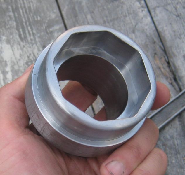 Use my plans at your own risk! Note to W116 and W126 owners - whilst your steering boxes have similar looking parts you might find that they are of different sizes! Development is in this thread http://www.peachparts.com/shopforum/diesel-discussion/298612-w123-300d-steering-box-question-about-steering-nut-working-piston.html How to use and where to use it in this one http://www.peachparts.com/shopforum/diesel-discussion/303379-what-feeling-will-properly-adjusted-w123-w116-w126-power-steering-box.html
__________________
1992 W201 190E 1.8 171,000 km - Daily driver 1981 W123 300D ~ 100,000 miles / 160,000 km - project car stripped to the bone 1965 Land Rover Series 2a Station Wagon CIS recovery therapy! 1961 Volvo PV544 Bare metal rat rod-ish thing I'm here to chat about cars and to help others - I'm not here "to always be right" like an internet warrior Don't leave that there - I'll take it to bits!
|
|
#27
05-29-2012, 03:05 AM
|
||||
|
||||
|
Here's another one that is quite easy to make!
W123 parking brake shoe retaining springs often seem like they have a mind of their own. The first time I tackled this job I lost it and just went for the bolt cutters!
Here's a more elegant solution. 1 X old flat blade screw driver 1 X slot cut in end of the screw driver 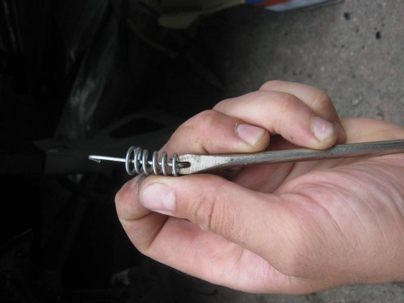 And here's the tool in use 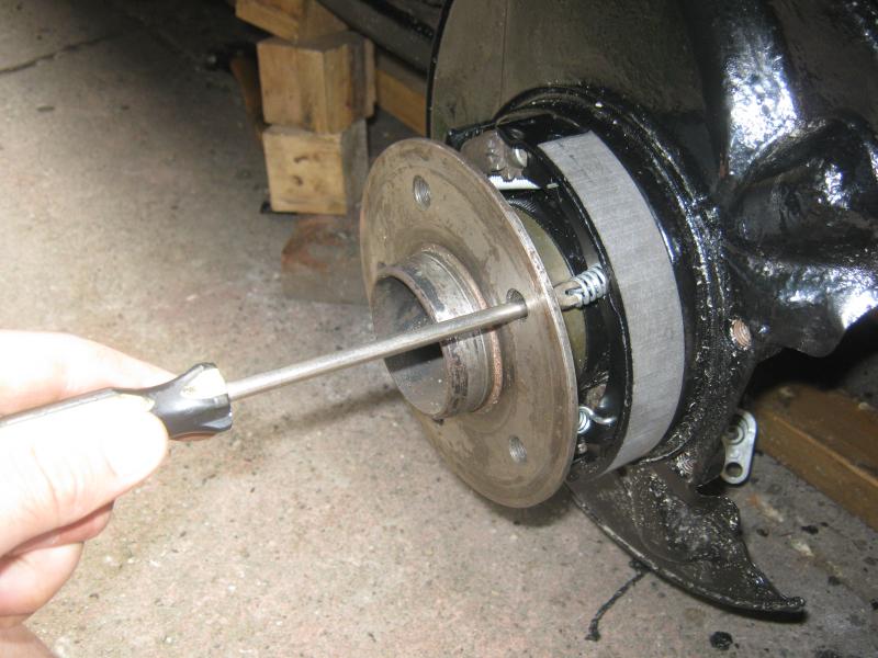
__________________
1992 W201 190E 1.8 171,000 km - Daily driver 1981 W123 300D ~ 100,000 miles / 160,000 km - project car stripped to the bone 1965 Land Rover Series 2a Station Wagon CIS recovery therapy! 1961 Volvo PV544 Bare metal rat rod-ish thing I'm here to chat about cars and to help others - I'm not here "to always be right" like an internet warrior Don't leave that there - I'll take it to bits!
|
|
#28
09-23-2013, 03:05 PM
|
||||
|
||||
|
Guide Rail Pin Removal Tool
BUILDER:
Forum member "DRACO A5OG". DESCRIPTION: Homemade guide rail pin removal tool for a Mercedes-Benz cylinder head. Constructed from a brass pipe fitting, a metric bolt, stainless steel washer, and nuts, it replaces a $150 special factory tool. Quote:
.
__________________
ASE Master Mechanic asemastermechanic@juno.com Prototype R&D/testing: Thermal & Aerodynamic System Engineering (TASE) Senior vehicle instrumentation technician. Noise Vibration and Harshness (NVH). Dynamometer. Heat exchanger durability. HV-A/C Climate Control. Vehicle build. Fleet Durability Technical Quality Auditor. Automotive Technical Writer 1985 300SD 1983 300D 1984 190D 2003 Volvo V70 2002 Honda Civic https://www.boldegoist.com/ Last edited by whunter; 09-23-2013 at 03:20 PM.
|
|
#29
09-23-2013, 03:26 PM
|
||||
|
||||
|
Mercedes 617 Crank Seal Tool
Homemade Mercedes front crankshaft seal installation tool fashioned from a 1-1/4" PVC union. Compatible with Mercedes-Benz Type OM617 diesel engines.
http://www.peachparts.com/shopforum/diesel-discussion/334484-1980-w116-300sd-om617-front-crank-seal-replacement.html#post3097659 .
__________________
ASE Master Mechanic asemastermechanic@juno.com Prototype R&D/testing: Thermal & Aerodynamic System Engineering (TASE) Senior vehicle instrumentation technician. Noise Vibration and Harshness (NVH). Dynamometer. Heat exchanger durability. HV-A/C Climate Control. Vehicle build. Fleet Durability Technical Quality Auditor. Automotive Technical Writer 1985 300SD 1983 300D 1984 190D 2003 Volvo V70 2002 Honda Civic https://www.boldegoist.com/
|
|
#30
11-14-2013, 02:59 AM
|
||||
|
||||
|
Body welding is difficult enough. Here is a DIY for making your own butt weld clamps
Body welding is difficult enough, butt weld clamps make hard jobs easier
Search results for: 'butt weld clamps' Auto Body Tools: BUTT WELDING CLAMP(4PCS) #CLZ650L - YouTube Here is a DIY for making your own butt weld clamps Interclamps- buttweld clips - YouTube .
__________________
ASE Master Mechanic asemastermechanic@juno.com Prototype R&D/testing: Thermal & Aerodynamic System Engineering (TASE) Senior vehicle instrumentation technician. Noise Vibration and Harshness (NVH). Dynamometer. Heat exchanger durability. HV-A/C Climate Control. Vehicle build. Fleet Durability Technical Quality Auditor. Automotive Technical Writer 1985 300SD 1983 300D 1984 190D 2003 Volvo V70 2002 Honda Civic https://www.boldegoist.com/
|
|
| Bookmarks |
|
|


 Linear Mode


