 |
 |
 |
 |

|


|
|
|
|
|
|
#1
|
||||
|
||||
|
w124 Seat Switch Repair Questions
Hi All:
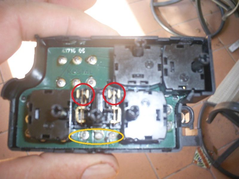
Been doing some searching and cannot find any info regarding repairing a passenger (non-memory) seat switch, specifically a post 1992 switch which has less internals than the earlier style switches with springs and balls etc. The later W124 switches use a series of micro-switches to soldered to a circuit board. The micro switches perform all of the same functions as the older style, but are each individually cased, and use spring connectors much like a relay that are switched with the movement of the respective switch pole. Each switch is encased in its own plastic box. So my seat bottom fore and aft movement has recently stopped working reliably. I know that the motors work, because after messing with the switch I occasionally can get the seat to operate fore and aft, but it wont repeat after letting go of the switch. I opened up the switch as the fore and aft is the only non-working function, i thought I could clean and restore function. Upon opening the switch case and confirming that the contacts were not positively connecting to the other poles when tripped. I cleaned the contacts, slightly bent the contact arms to ensure positive connection when activated, yet after hooking up to test, nada, nothing, as if nothing was done. I also checked power to the switch contacts with the cover removed and was getting 12V to the static poles, but no motor engagement when the switch contact was tripped, even manually. I'm stuck, the contacts work as they should mechanically, but not electrically  Does anyone know what is on the underside of the PCB? The board seem attached to the plastic case via the solder joints attaching the backside of the male plug pins. I see three plastic guides two of which are melted but after cutting them flush, the board remains rigidly affixed, and seeing no other connection method I assume that the pins are preventing lifting it from the plastic casing. Not sure if there is circuitry that might be preventing the current to flow all the way through. Any ideas? switch wiring diagrams? TIA Picture: Red circles are contacts for fore/aft switch, yellow oval is the three pole connection with the wiring harness, presumably for the fore/aft function [IMG]  [/IMG] [/IMG]
__________________
Stable Mates: 1987 300TD 310K mi (Hans) 2008 Jeep Grand Cherokee OM642 165k mi (Benzrokee) |
| Bookmarks |
|
|