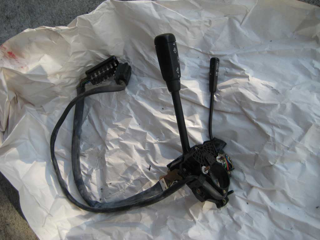
Combination Switch Replacement
on the 1987 300D (W124)
by sixto
08/14/11
DIY 1987 300D (W124) Combination Switch
Putting this out for review -
The combination switch includes the switchgear for the turn signals, windshield wipers and cruise control. The cruise control switchgear can be separated from the main combination switch but 95% of the work is common. Unlike in a W123, the W124 requires removal of the steering wheel and lower dash panel to remove and replace the combination switch. Let's get to it!
My tool list includes:
- Philips screwdriver
- Flat tip screwdriver
- T25(?) Torx driver (or 4mm wobble hex key)
- 8mm socket and driver
- 10mm hex bit and breaker bar (or impact wrench)
- 24mm socket (or long nose pliers)
Precautions:
- Since the airbag has to come off, disconnect the battery.
- Since the park brake release is attached to the lower dash panel, chock the wheels.
Removal of the steering wheel and lower dash panel are separate tasks. It doesn't matter which is done first.
Steering wheel:
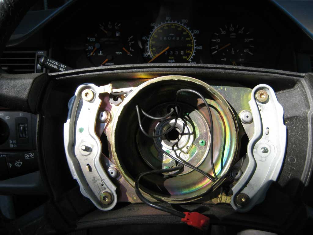
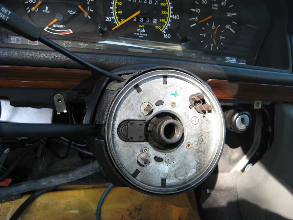
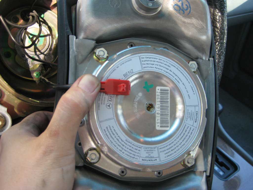
There are two holes on the hidden side of the steering wheel, one on each side of the steering column. They provide blind access to screws holding the airbag to the steering wheel. I use a 4mm wobble hex key to loosen the screws. I believe the proper tool is a T25 Torx driver (which I don't have available to me). The screws are captive, meaning they remain attached to the steering wheel once the airbag comes free.
With the airbag free, use a small flat tip screwdriver to to pry the red connector from the airbag. I'm not able to pull off the connector with my fingers. Set aside the airbag.
Have an assistant hold the steering wheel while you remove the bolt holding the steering wheel to the steering column. The bolt takes a 10mm hex bit. Use as long a breaker bar as is available or try an impact wrench. It might be possible to use the steering shaft lock to hold the steering wheel but replacing the steering shaft lock is too involved a task, and I enjoy rebuilding engines and transmissions, for me to risk it. It seems like there is thread locking compound on the bolt. I wouldn't try heat because of all the plastic and wiring in the area.
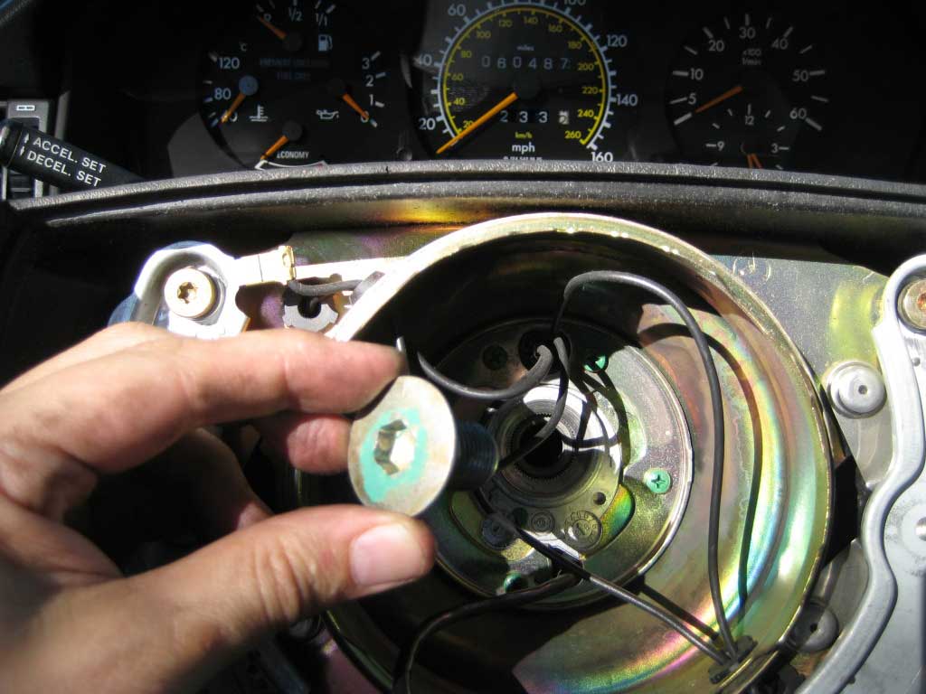
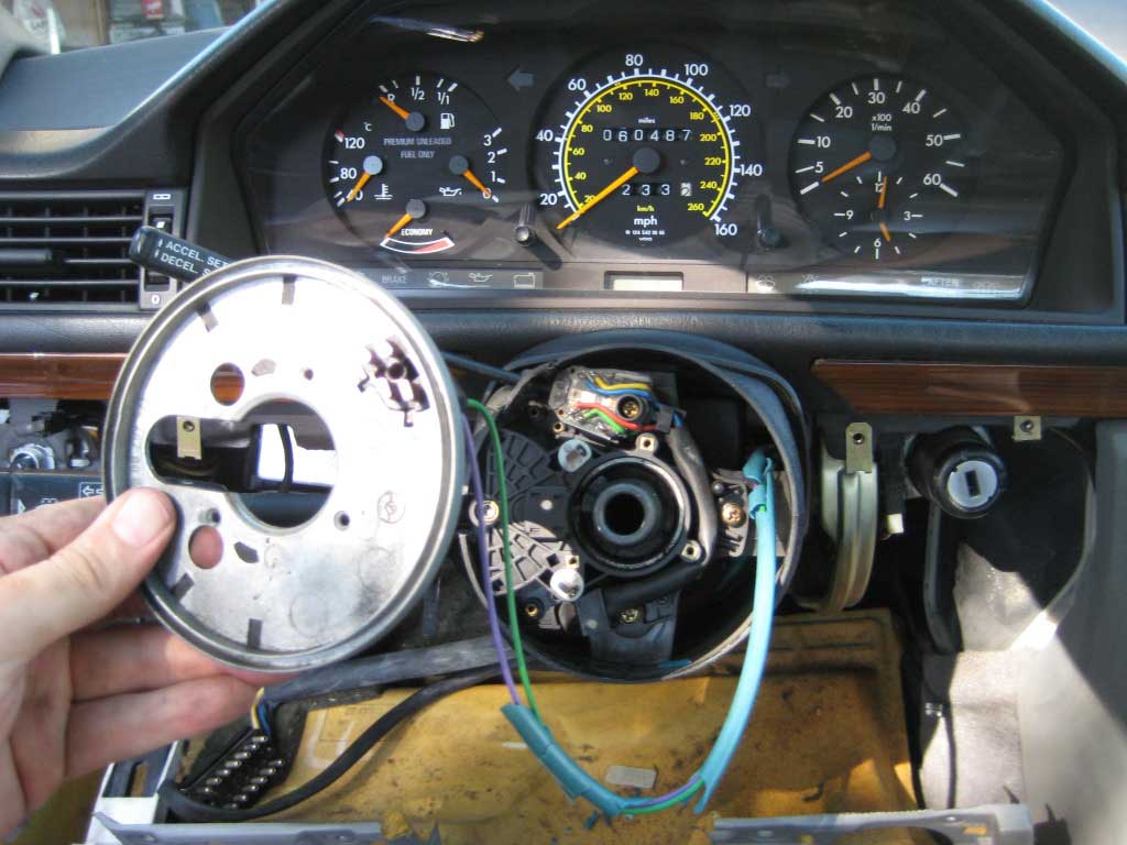
With the bolt off, note the orientation of the steering wheel so you can install it in the same orientation. Make alignment marks if necessary. Wiggle the steering wheel off the steering column. All the wires in the steering wheel can remain in place. Set aside the steering wheel.
Lower dash panel:
Pull off the headlight switch knob. Don't be shy, give it a good tug. Remove the nut revealed by removing the headlight switch knob with a 24mm socket. Long nose pliers seem like a possible alternative.
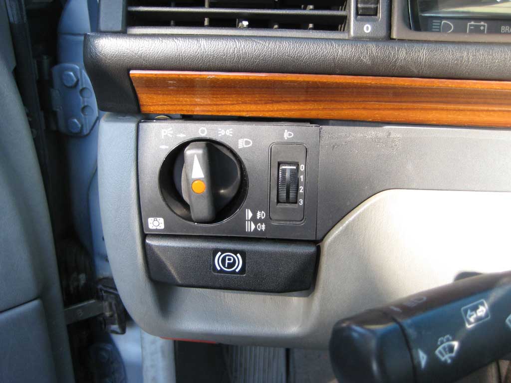
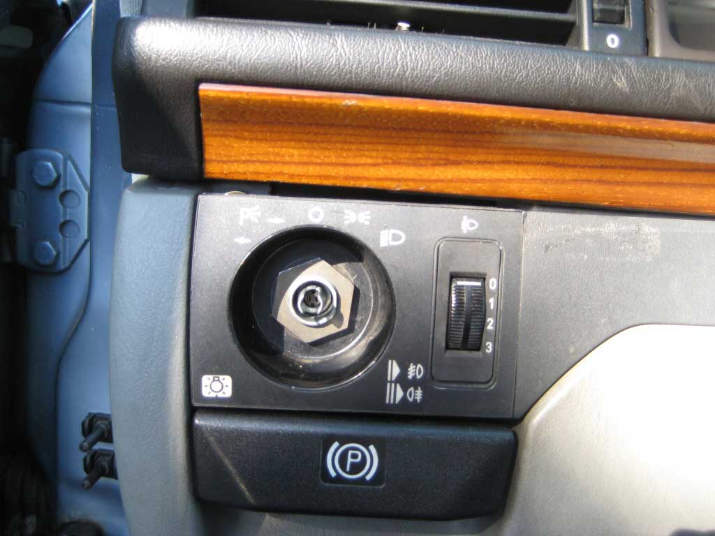

Pull the left end of the outboard black trim panel away from the dash. There are two clips on the narrower portion of the trim panel that might need a little prying.

The trim panel will be retained by the headlight switch illumination bulb. Squeeze the sides of the bulb holder and wiggle it off the trim panel. You might have to squeeze the top and bottom of the holder rather than the sides. The inside end of the trim panel tucks under the steering column trim so pull away from the dash and away from the steering column. Set aside the outboard black trim panel. Remove 3 screws using an 8mm socket and driver.

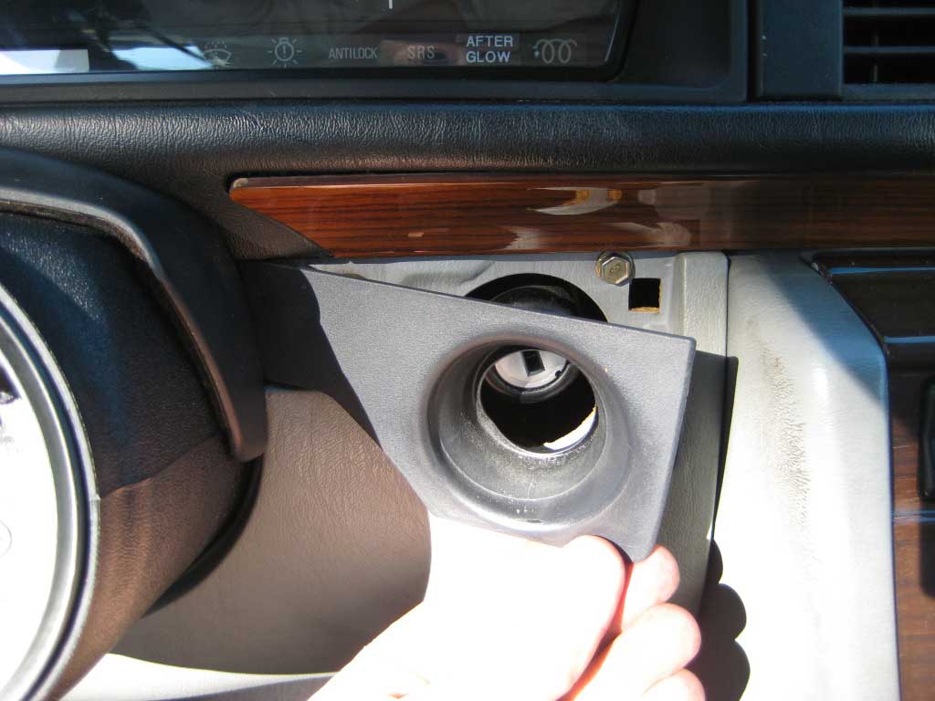
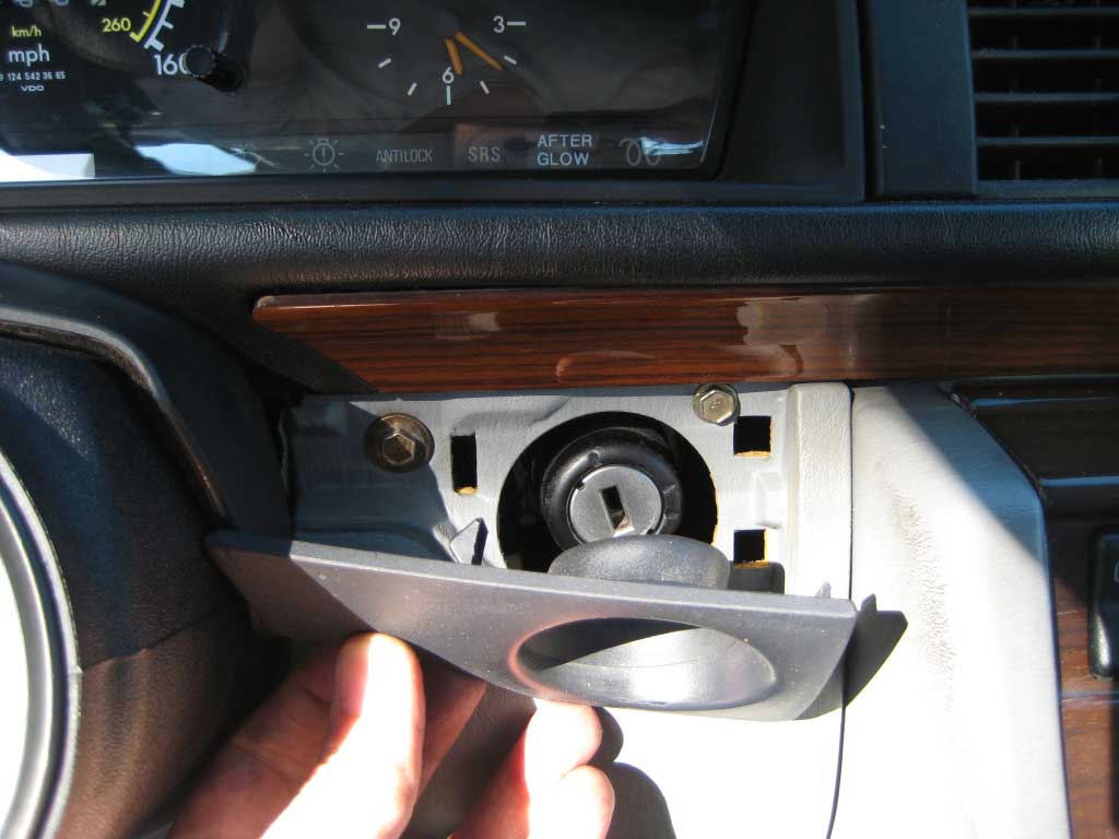
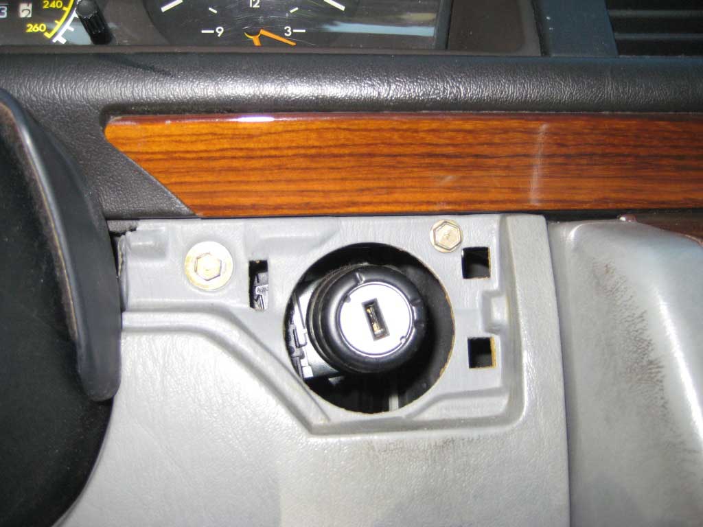
Pry the right end of the inboard black trim panel, the one around the key switch, away from the dash. There are 3 tabs to release while pulling away from the dash, then pull away from the steering column. Set aside the inboard black trim panel. Remove 2 screws using an 8mm socket and driver. Note that the screw closer to the key switch has a smaller washer.

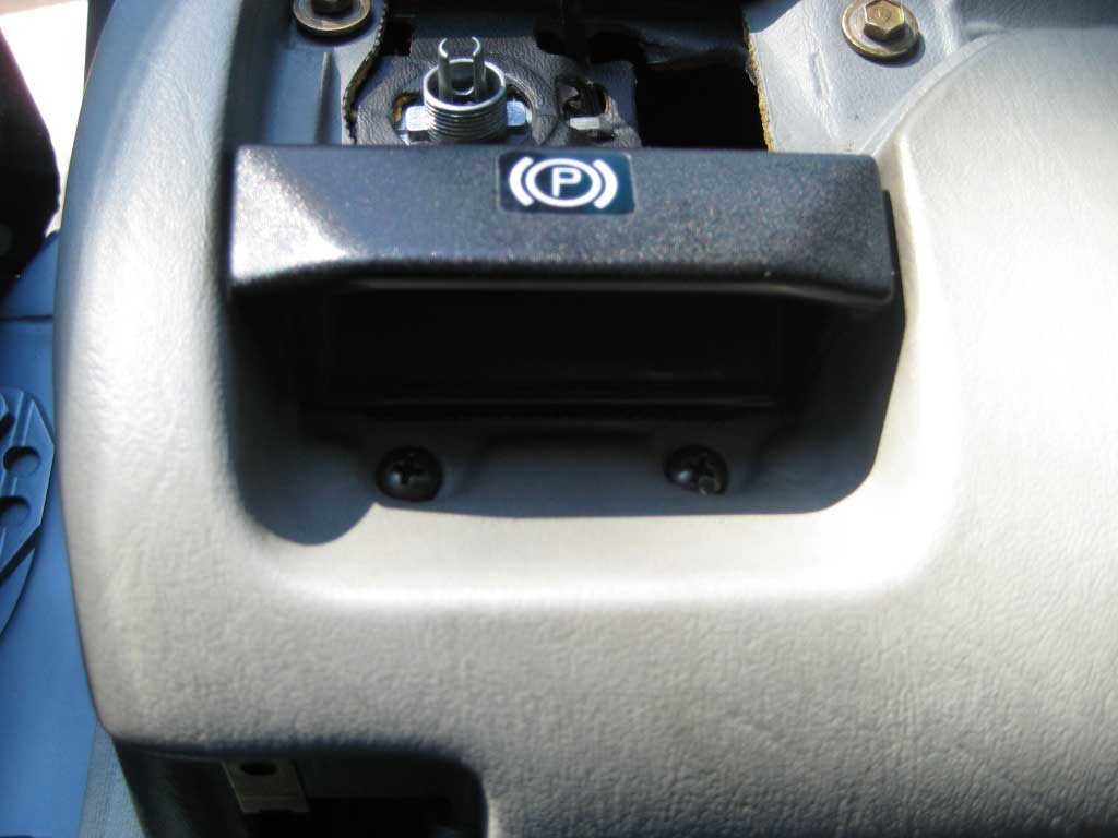
Remove 2 black screws under the park brake release handle using a Philips screwdriver.
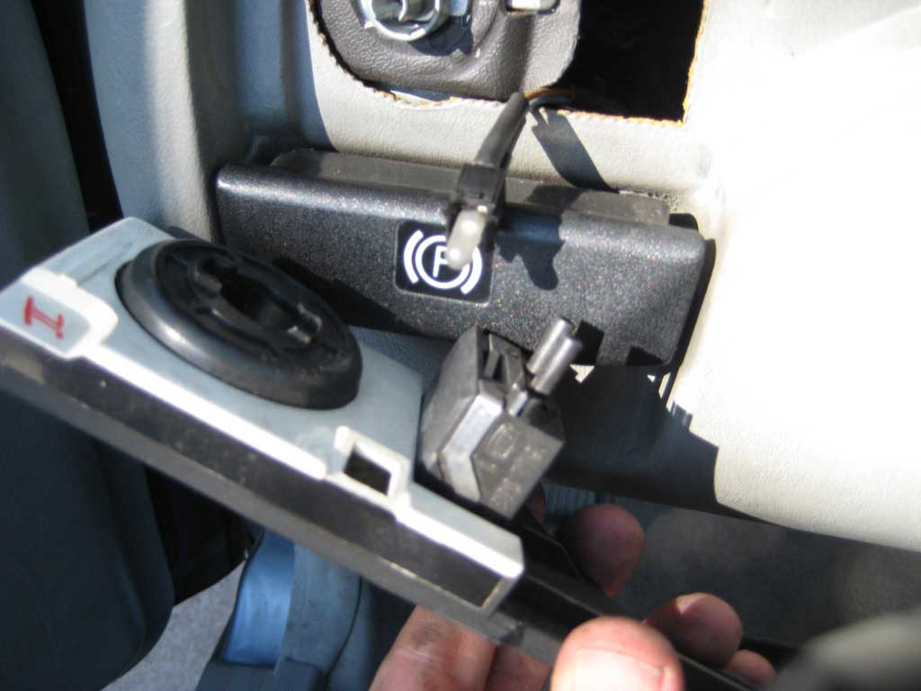
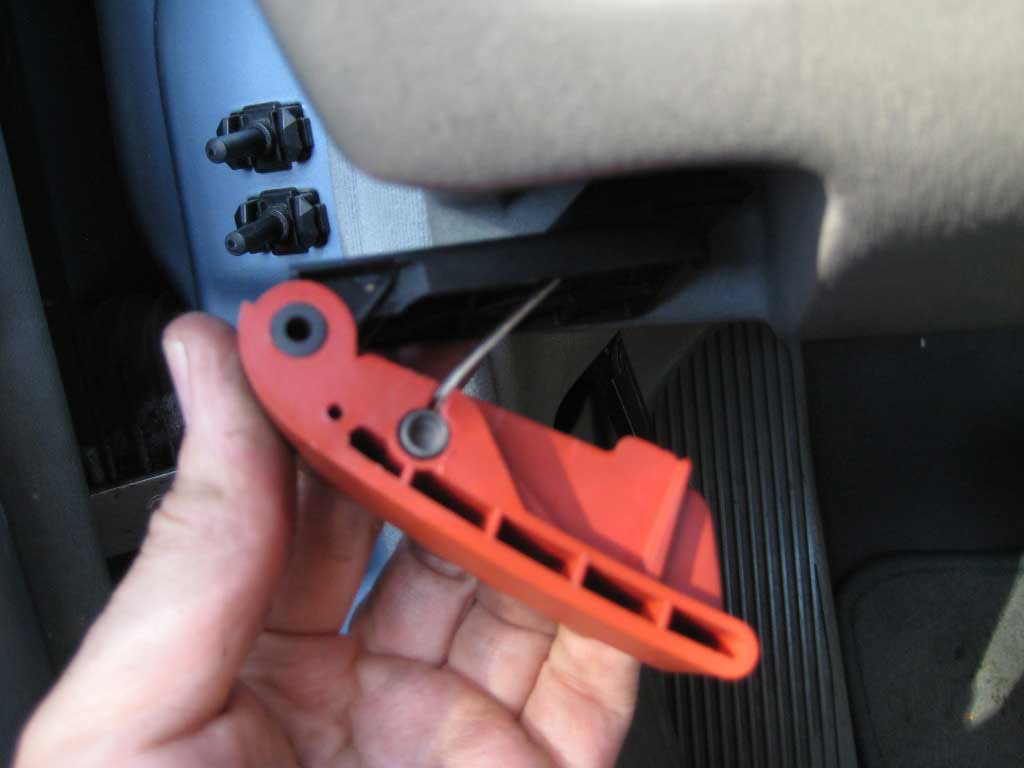
Remove 1 screw holding the hood release lever to the dash.

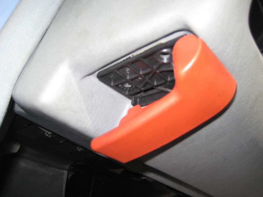
Pull the hood release lever downwards and away from the dash. Note the hammer end of the hood release cable and rotate it such that the hammer and cable slide through the slot free of the red handle. Slip the cable out of the black guide tube. It might be possible to leave the hood release lever attached to the lower dash panel but I find insufficient room to work on the various electrical connectors.
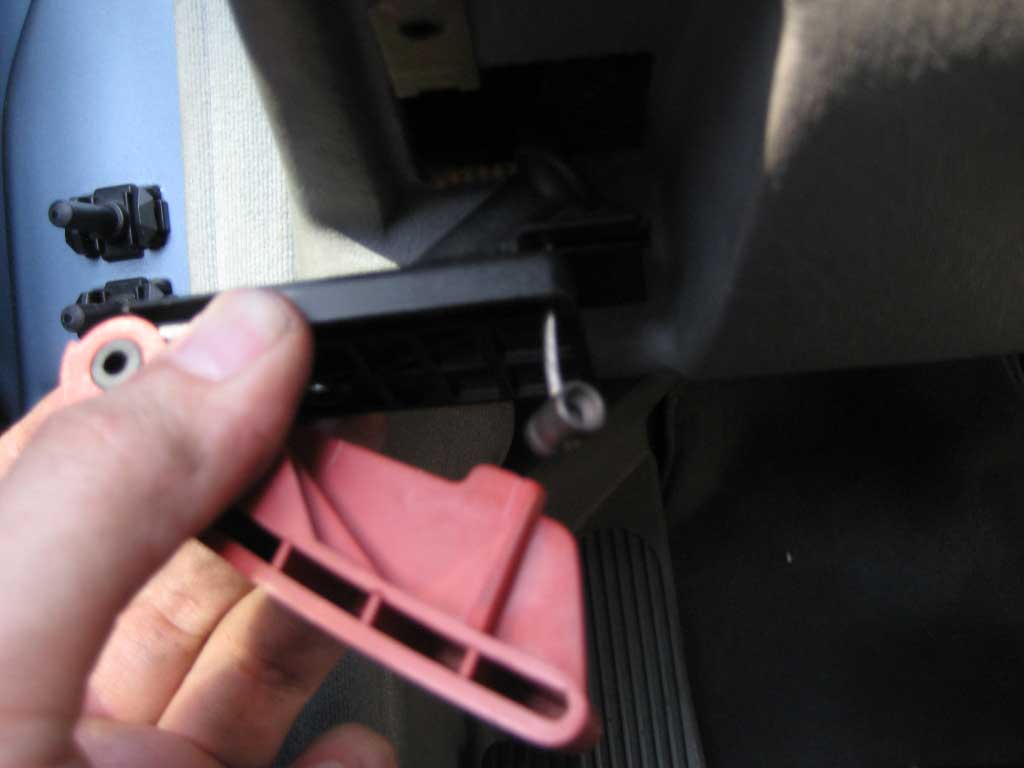
The park brake release cable can remain attached.
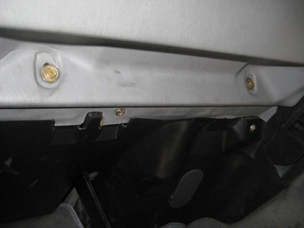
Remove 2 screws along the bottom edge of the lower dash panel using an 8mm socket and driver.
Pull down the lower dash panel. Note that the lower dash panel is somewhat pinched by the steering column trim. You should have enough room for the work to be done without completely removing the lower dash panel.

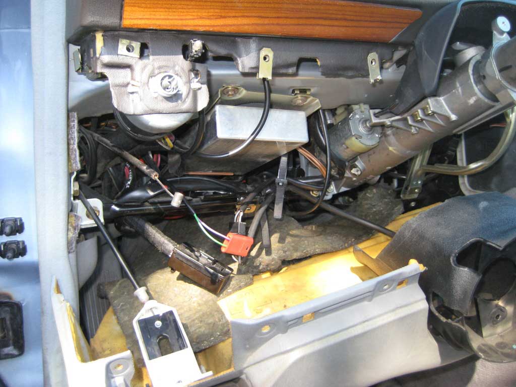
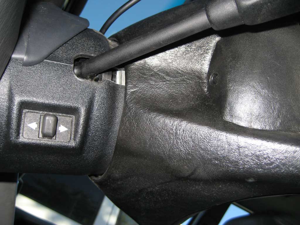
Combination switch:
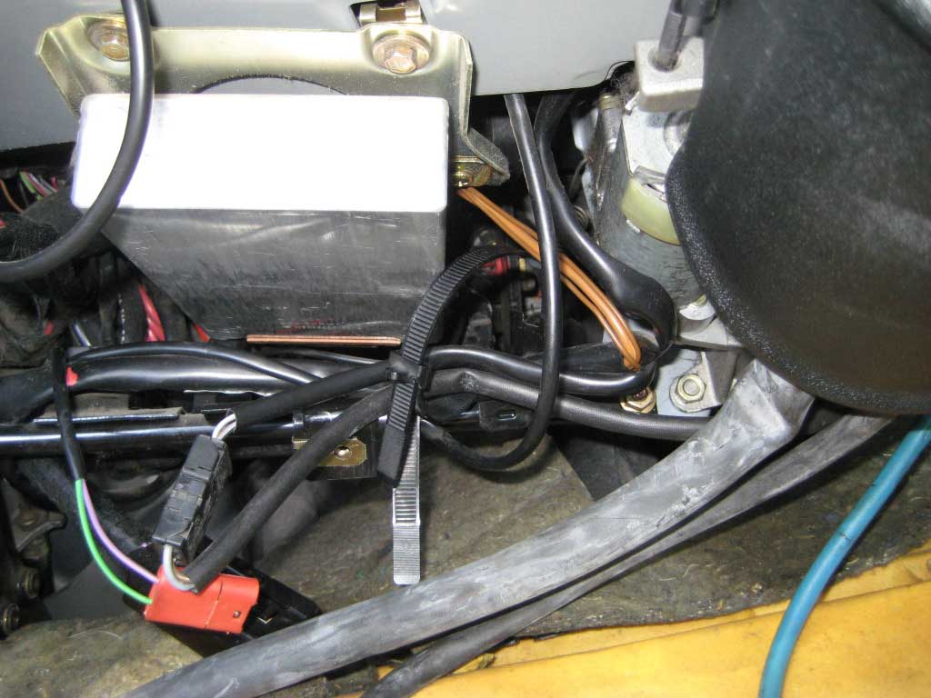
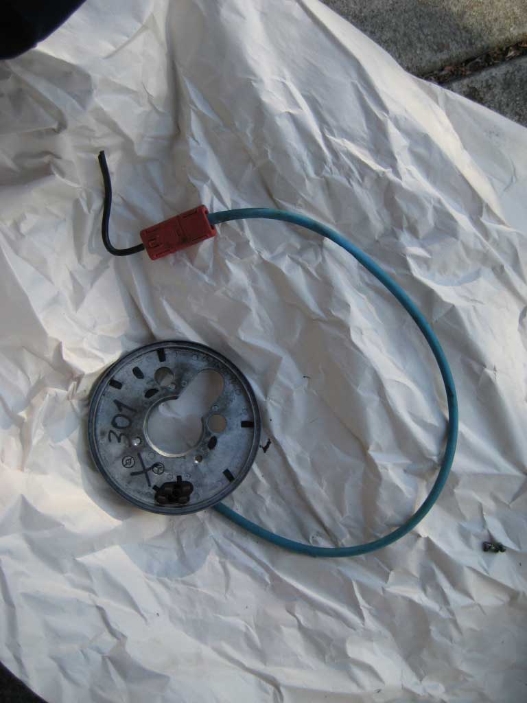
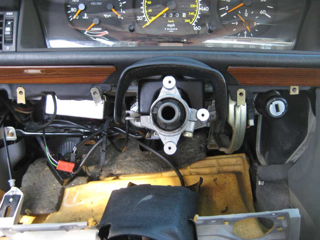
Locate the 14-pin connector below the silver cruise control unit outboard of the steering column. Separate the 14-pin connector. The female half of the connector has a retention tab molded into the case but I don't see where it can attach.
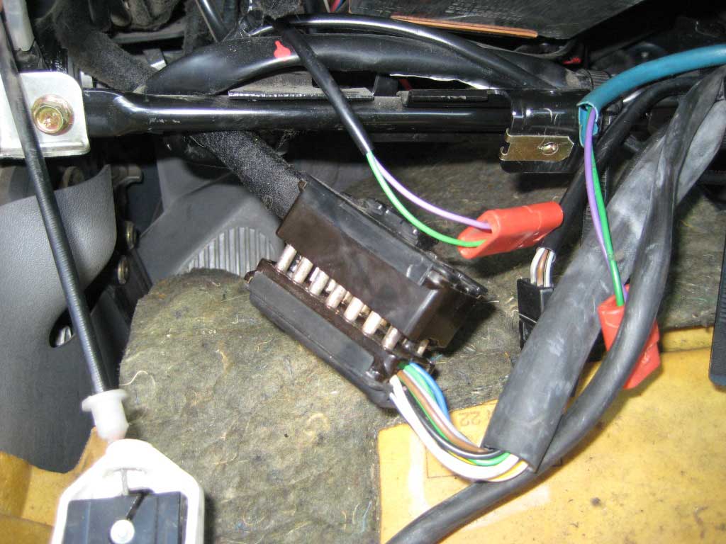
Locate the 6-pin connector outboard of the silver cruise control unit. Separate the 6-pin connector. The female half of the connector is fixed in place.
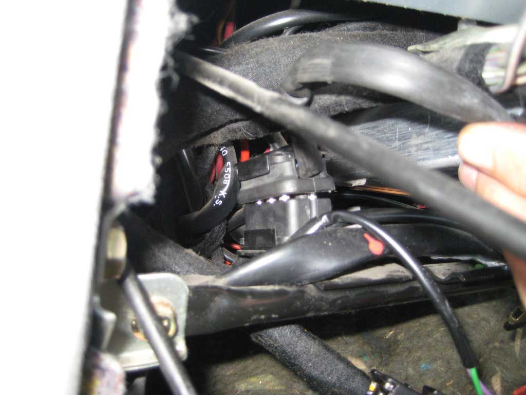
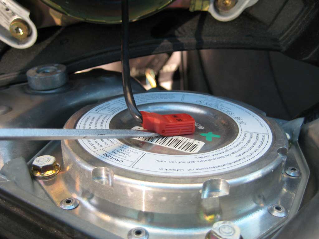
If you plan to fully remove the airbag contact plate, locate the red 2-pin connector. There is a tab in one end of the connecting halves. Either push in the tab or pry up the corresponding slot to separate the halves.
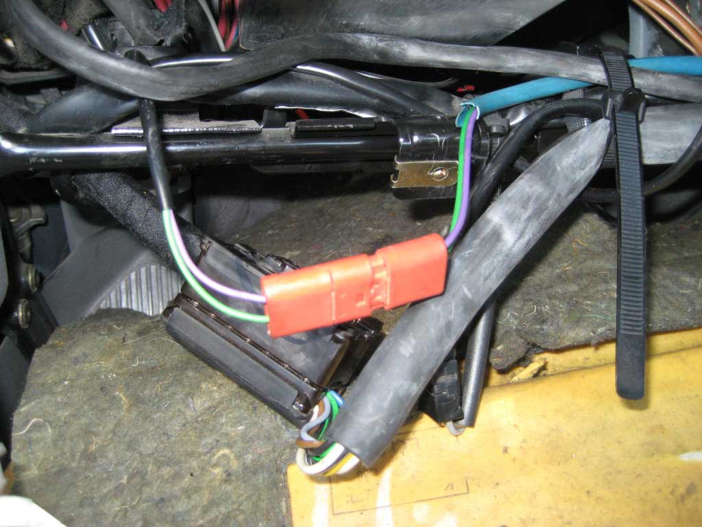
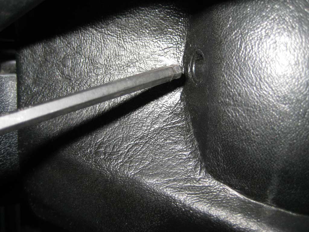
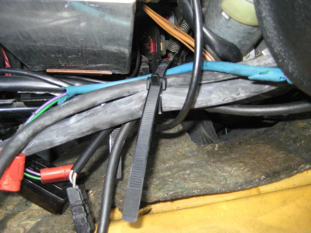
Locate the wire tie holding the wire bundles from the 14-pin connector and 6-pin connector. Push the tab in the wire tie away from the slotted surface of the wire tie and feed the loose end of the tie through the retainer to enlarge the opening of the wire tie. No need to fully open the wire tie.

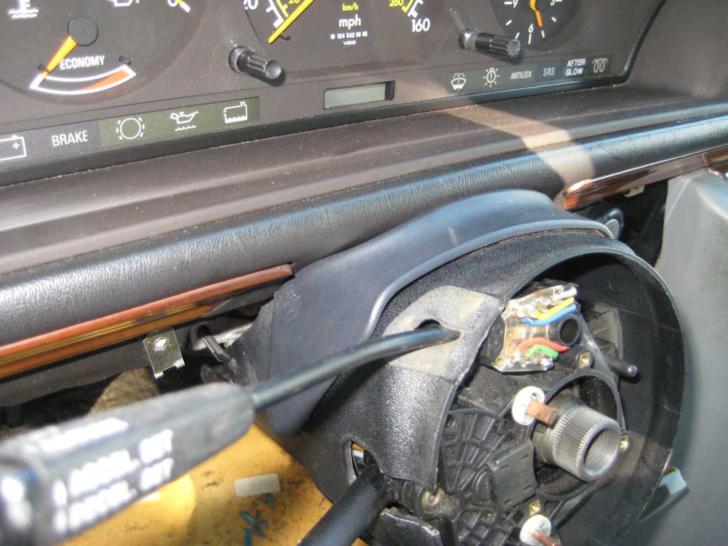
Remove 3 Philips head screws holding the airbag contact plate to the combination switch. Set aside the screws.
Pry the airbag contact plate from the combination switch. You can leave the contact plate dangling. The blue sheath around the airbag wires can be brittle and fall apart as you move the airbag contact plate. If you want to remove the airbag contact plate, thread the blue sheathed wire bundle from the released red 2-pin connector through the enlarged wire tie and up the steering column trim. Set aside the airbag contact plate.
Remove 3 Philips head screws holding the combination switch to the steering column. Set aside the screws. Note that a longer screw without a washer(?) holds the cruise control switchgear to the combination switch and steering column.
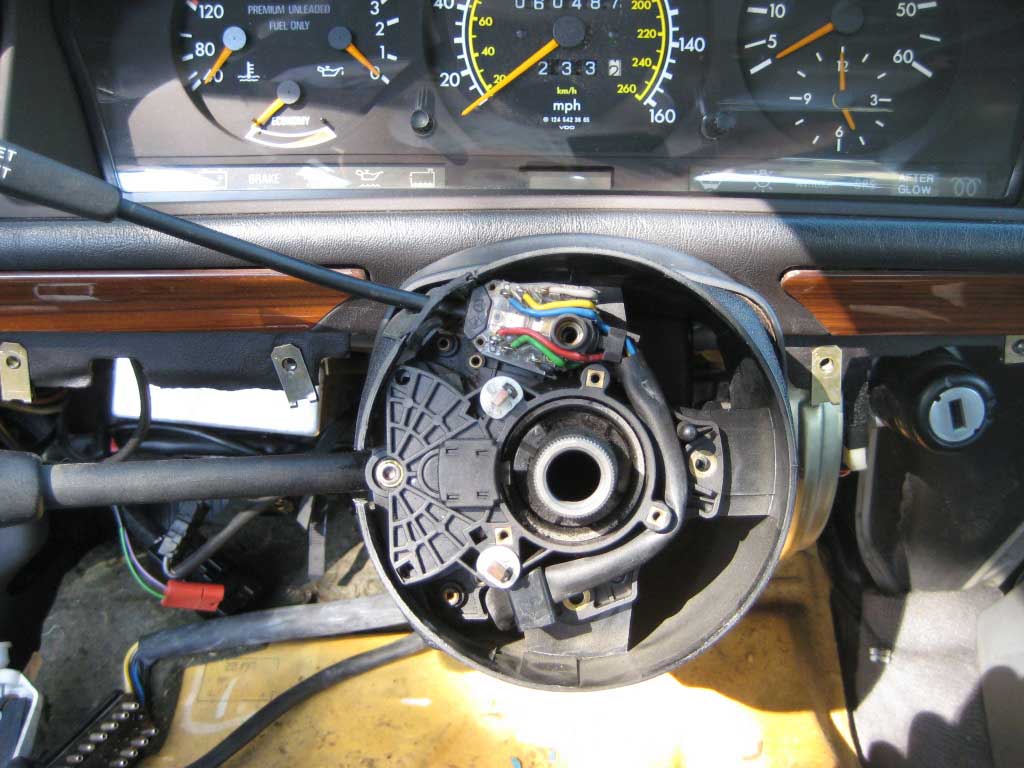
Pry the combination switch from the steering column. Thread the wire bundles from the released ends of the 14-pin and 6-pin connectors through the enlarged wire tie and up the steering column. It is a tight fit for the 14-pin connector around the telescoping steering column switch (if equipped) in the steering column trim. Set aside the combination switch.

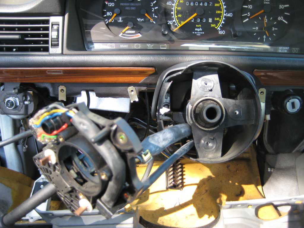
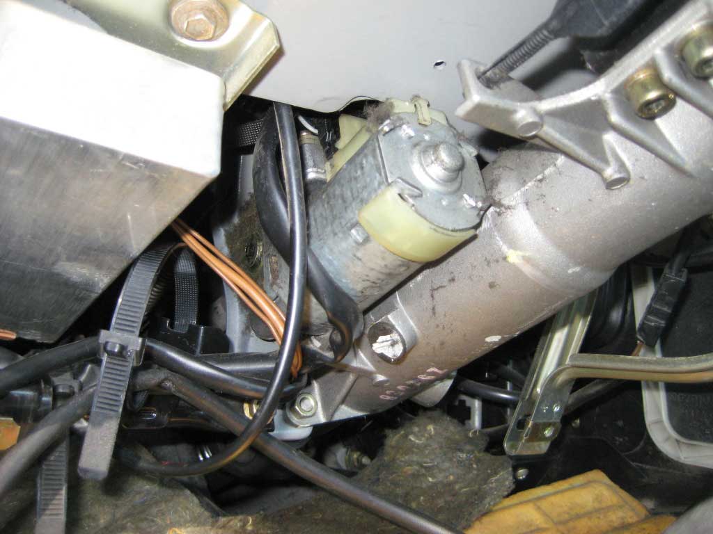
Although the telescoping steering column switch and motor are visible at this point, there is considerable disassembly of the steering column required to remove the telescoping steering column motor. The switch is easy to replace at this point but it looks to be part of the steering column trim. With the combination switch out of the way, the steering column switch pulls easily off with the steering column.
Haynes time! Assembly is the reverse of removal. For the most part, it is.
Some things to look out for:
- There is a piece of rubber trim around the cruise control stalk. The edges of the trim are slotted to go around a tab in the steering column trim. Get this piece of rubber trim correctly in place before the steering wheels goes back in place.

- Neither my car nor the two combination switch donors had a piece of rubber trim around the turn signal stalk.
- Route the wire bundles through the wire tie and retighten after all the wire bundles are connected.
- Do a trial fit of the lower dash panel to ensure all the insulating pads and wires are clear of the screw holes.
- Make sure you thread the hood release cable to the slot in the lower dash panel through which the cable reaches the hood release lever. You can wait until the lower dash panel is securely in place before attaching the hood release handle.
- Set the hood release cable back in the black guide tube set the hammer and cable in the hood release lever.
- Make sure the nut clips for the screws holding the lower dash panel in place are in place and did not slide out of place or fall off.
- Don't forget to attach the headlight switch illumination bulb and holder to the outboard black trim panel.
- Note that there are 2 pins in the airbag connector. I don’t believe there is clocking or polarity to consider.
- The airbag retention screws are self aligning and pretty good at it too. Turn the screws while holding the airbag to the steering wheel and the screws should engage and tighten.
Moment of reckoning:
- Decide whether you can live with any leftover parts

- Reconnect the battery and make sure everything works as it should. The airbag warning light shouldn't remain illuminated after the engine starts.
Sixto
87 300D
Discuss this DIY here.
-sixto
CategoryDiy