|
Turbo Technics Limited
Fitting Instructions
Mercedes 24v 320E
1. Disconnect the battery, drain the engine oil and water coolant into clean containers.
2. Remove the air filter assembly.
3. Remove the complete exhaust system.
4. Mark the positions of camshafts to crankshaft and remove the cylinder head.
5. Remove the water radiator, support the transmission to remove the engine crankcase.
6. Remove the sump pan and carefully remove all pistons, marking their original positions.
7. Remove the pistons from the connecting rods, marking their positions.
8. On catalyst equipped cars, cut the catalyst from the exhaust downpipes.
9. Send the pistons, connecting rods, throttle body, clutch cover (manual transmission cars only), and catalyst to Turbo Technics, Northampton, for machining.
10. Position the intercooler under the offside chassis rail, parallel with the engine.
Slide the intercooler backward until the end tank (with two inlet pipes) touches the chassis cross member.
With the intercooler in this position, mark through the two mounting holes.
11. Remove the plastic plate behind the offside headlight (where two chassis rails converge).
12. Fit the intercooler with two self-tap screws.
Offer the GRP air duct up to the intercooler and locate onto the two studs used to secure the aforementioned plastic cover.
This operation is simplified if the front bumper assembly is removed.
13. Bolt through the air duct and intercooler lower bracket and through into the rear intercooler end tank.
(The tapped hole on the front intercooler end tank is used to replace the engine heat shield mounting).
14. Depending upon the type of front bumper spoiler, either:-
a. Remove the blanking plate behind the grille section to allow air to flow into the intercooler ducting.
OR
b. On plain spoilers with no grille, mark out and cut a number of neat slots to allow a maximum amount of air through.
Fit the plastic dividing plate to direct air flow into the ducting rather than through the water radiator.
15. i)Slacken and remove the engine drive belt.
ii) Remove the air pump, alternator and mounting bracket.
iii) Remove the idler mounting bracket.
iv) Re-fit the idler pulley onto the new mounting bracket and re-fit.
v) Re-fit the alternator onto the new lowered bracket.
vi) Fir the new drive belt and tension.
16. Remove the water drain plug from the engine block - this will supply the water coolant to the turbocharger.
17. Drill and tap both oil drain positions into sump (drawing number 3177). Carefully screw in the 45° oil drain fitting using thread sealer.
Fit the soft washers into the inside of the sump and screw onto the nuts. DO NOT OVER-TIGHTEN.
18. Remove the oil pressure switch above the flywheel and replace the fittings used for the turbocharger oil feed pipe.
19. Re-fit the pistons to the shortened connecting rods carefully, and re-assemble the engine.
20. Re-fit the modified clutch cover to the flywheel (manual transmission only).
21. Replace the crankcase back into the vehicle.
22. Remove the exhaust manifolds from the cylinder head,
i) Remove the air pipe above the exhaust manifolds.
ii) Fit core plug into the hole to seal.
23. Fit the new exhaust manifolds to the cylinder head. Bolt the exhaust elbows into the turbochargers, (the elbow with the heat shield must be used on the front turbo).
24. Fit both oil drain pipes into approximate positions, they can be tightened after aligning, once the cylinder head is fitted.
25. Replace the cylinder head. Re-fit the cam chain.
26. Replace the sparking plugs.
27. Fit the water pipes from the engine block to the turbochargers.
Fit the 'P' clip onto the front turbo water pipe, securing with a bolt into threaded boss in the side of cylinder block.
28. Connect the oil drain pipes.
29. Fit the rear compressor outlet silicon hose, slide the short length of silver convoluted hose into position to protect the horizontal length of silicon hose from the exhaust manifold heat.
30. Connect the front compressor outlet to intercooler silicon hose.
31. Fit the air filter inlet duct at the top of the gap between the headlight and the radiator. Fit the convoluted hose to the duct.
32. Replace the radiator and mount the air pipe vertically next to the radiator. Remove the nearside headlight to drill through.
Gauge the position by ensuring that the link pipe from the intercooler is horizontal.
33. Cut the nearside plastic under shield to allow flexible ducting to pass through to the air filter.
34. Position the air filter under the nearside inner wing. Mark around the outlet and cut a hole in the inner wing.
Drill through the mounting lugs on filter body. Fit the air filter element and mount the air filter assembly.
35. Fit the 110.0mm long silicon hose to the outlet. Fit the metering unit, metering unit outlet hose and air pipe casting, using the bracket supplied.
36. Cut the original air pipe over the engine, as close to the end of the oval section on the nearside as possible. Fit to the casting using the silicon hose supplied.
37. Fit the compressor inlet silicon hoses.
38. Remove the front bumper. Cut away the plastic fan shroud below the cross member to allow more cooling for the radiator.
39. Screw the breather stub 90° into the air cross pipe casting.
40. Cut the water hose from the electric water pump to the engine just after the 90° turn at the pump end.
Turn around the longer remaining hose onto the engine. Fit the steel extension pipe to re-connect the hose to gain clearance from the air filter lid.
41. Fit the oil feed hose to the turbochargers. Use three double-ended studs to mount 'P' clips on.
NOTE: Ensure that the oil feed hose maintains clearance from the brake pipes across the bulkhead.
42. Fit the short fluorocarbon hose to the throttle body inlet.
43. Assemble injector to throttle body casting using the 'O' rings supplied. Fit the assembly to the hose.
44. Disconnect the fuel inlet hose at the fuel rail. Fit the 'T'-piece and short 50mm long hose to connect up to the manifold. Use the other hose to connect to the injector.
45. Fit the wiring loom for the additional injector. Carefully wrap to the contact pins with insulation tape before pushing through the grommet on the bulkhead.
Locate the DCU under the passenger side floor panel using the bracket supplied.
46. Connect the over boost protection relay next to the Mercedes ECU behind the battery. Remove the MAS unit adjacent to the ECU by turning the top knob.
Locate the fuel pump feed wire (black/red with white stripe) at the front of the multi-plug to the over boost relay red/black wire.
Connect the remaining black/white wire to the longer cut wire. Solder all connections and insulate using shrink wrap.
47. Connect the silicon hose from the intercooler outlet pipe to the injector mounting.
48. Fit the two turbo water outlet 90° pipes. Connect the molded silicon hose from the rear turbo to 'tee' into the water coolant hose adjacent to the expansion bottle.
Connect the straight silicon water hose from the front turbo water outlet to 'tee' into the same hose between the radiator and the air filter box.
49. Fit the engine breather systems incorporating the mio-filter and one-way valve.
50. Fir the complete exhaust system. The catalytic converter is not retained in the system, but the Lambda sensor must be fitted into the boss.
On Coupes, the outlet pipes from the center silencer need reducing in length. The original exhaust mounting bracket from the gearbox is retained.
51. Fit the two turbine chrome heat shields.
52. Run the engine, checking for leaks, until normal water temperature is achieved.
53. Re-torque the cylinder head bolts.
54. Road test the vehicle, checking boost pressure - see service instructions.
__________________
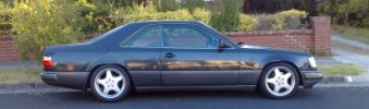
1989 300CE "Project HWA124"
(400rwhp Turbo Technics AMG C36 engine)
Last edited by whunter; 03-12-2009 at 12:12 PM.
Reason: spelling
|