

|
|
|
|
|
|
|
|
#1
 05-05-2012, 09:06 PM
|
|||
|
|||
|
'85 300TD tach issues (Don't worry I've searched the forum)
Hi all,
trying to get my tach working again. I know it's not vital but I'd really like to have it working - as I get my trans and engine dialed in I'd like to have that reference for myself and I have never really tried to tune any engine. I've searched the forum A LOT, here is what I've done: - pulled speed sensor and wiped clean - checked voltage from speed sensor, checks out fine - changed OVP relay with another from a PnP car. Mine was really rattling. Not sure the 'new' one is working - OVP relay fuse (it was blown) - Pulled connector off the EGR computer, cleaned the ***** out of the pins and pin connectors, and replaced the female connector on the bottom which looked the worst Known issues: - OVP relay. From a PnP car so can't really tell if it's working as it should - There is one part of the instrument cluster circuit board that has burned through. Very minor, no damage to the board, however that burned through spot is behind temp, oil and fuel gauges which are all working fine. - Lots of corrosion on the EGR computer pins and connectors. Nothing seemed to have penetrated the module itself but there was definitely moisture in the area After all of that, when I am accelerating, the tach needle is all the way to the LEFT, when I let off the gas the needle swings all the way to the RIGHT. So clearly the gauge is getting some information, the speed sensor is putting off what it should, the strange gauge behavior is not what I would suspect from a bad OVP relay. All this seems to me to point to a bad EGR computer. For what it's worth the previous owner disconnected the vacuum lines to the EGR, which I have not plugged back in. Not sure what it's worth. Am I missing something? Anyone have a similar experience? 
|
|
#2
05-05-2012, 10:02 PM
|
||||
|
||||
|
Quote:
[1] Variable Reluctor sensor (82) - On the transmission (reads flywheel teeth) [2] EGR Computer (80) - processes signal [3] Tach (a) - signal to gauge [4] OVP (85) = provides power to controller  You can't really test the VR sensor without a scope as it puts out A/C current. But these are generally bullet-proof - the least likely suspect. Just check for good wiring and make sure the sensor is solidly in place. (Actually there is a way to test the VR sensor - see below for a simple VR tester setup) You can look for 12v on pin 1 to verify the OVP (or take power from an unconditioned source for testing). You could pull a tach unit from the JY to test the actual gauge (or pull the unit and test it in a known good vehicle, if you have a friend with one) If those all test good, you're most likely point of failure is the controller. Because of the corrosion you report on the contacts, I'd probably bet on that being the problem. VR Tester When I was working on my mechanical to electronic speedometer conversion I rigged up a VR tester, like this It was just a convenient hole saw with a number of nuts taped to the circumference. (I used 4 for the speedometer because there are 4 teeth in the trigger wheel at the rear of the transmission) Nuts aren't the best because they have a hole in it that could create the appearance to the system of two teeth. In your case I'd suggest using something solid with as many "teeth" as possible for the trigger wheel and about 1/2" high (the one on the flywheel - flywheel starter ring teeth actually) has around 50. Then to test, take the VR sensor out of the intermediate plate and hold it close to the make-shift trigger wheel "teeth" and watch the tach. You should see a smooth rise as you increase the speed on the drill (assuming everything else is functional).
__________________
Current Stable
|
|
#3
09-17-2014, 10:01 AM
|
||||
|
||||
|
Quote:
__________________
85 300D turbo pristine w 157k when purchased 167,870 July 2025 83 300 D turbo 297K runs great. SOLD! 83 240D 4 spd manual- parted out then junked
|
|
#4
05-05-2012, 11:41 PM
|
||||
|
||||
|
... I'm picturing you using this tester...
"ok, hold the rpm steady, steady, a little closer... AHHHAHHHAHAHAHHAHHAHH!!!"
__________________
John HAUL AWAY, OR CRUSHED CARS!!! HELP ME keep the cars out of the crusher! A/C Thread "as I ride with my a/c on... I have fond memories of sweaty oily saturdays and spewing R12 into the air. THANKS for all you do! My drivers: 1987 190D 2.5Turbo 1987 560SL convertible 1987 190D 2.5-5SPEED!!!  1987 300TD 2005 Dodge Sprinter 2500 158"WB 1994GMC 2500 6.5Turbo truck... I had to put the ladder somewhere!
|
|
#5
05-05-2012, 11:52 PM
|
||||
|
||||
|
Quote:

__________________
Current Stable
|
|
#6
05-06-2012, 09:33 AM
|
|||
|
|||
|
Is the way to test the OVP relay to pull it, figure out which pin is pin 1, then push the relay back in leaving a gap for the multimeter probe?
Seems that assuming the relay passes that test I can narrow it down to the EGR controller or the gauge itself. Since I got a good multimeter reading from the speed sensor, would using the hole saw of destruction test give me any new information? Guess it is worth trying before replacing the EGR controller. Aside: Anyone know what #80 in the diagram is doing? Just says switchover valve - what is being switched over?
__________________
'85 300TD
|
|
#7
05-06-2012, 10:52 AM
|
||||
|
||||
|
Quote:
Here's a diagram of the connector I created to help in my swap  I would just pull the plug and apply a multimeter to pin 1 and see if you've got good voltage. Here is diagram of the vacuum showing the #81 Switchover Valve, which applies vacuum to the Air Recirculating Valve. 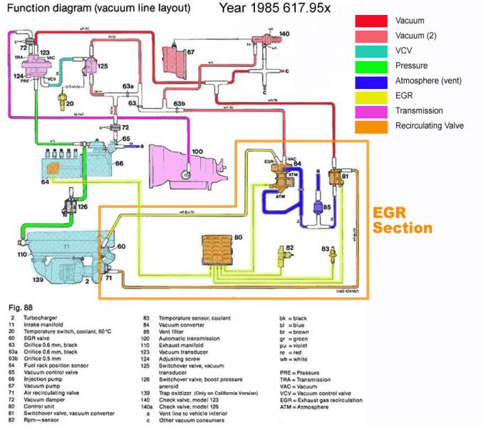
__________________
Current Stable
|
|
#8
05-06-2012, 11:21 AM
|
|||
|
|||
|
Those are two of the most helpful pictures I've seen. Thanks so much for taking the time to do that!
It should be around 12V, right? Will it be DC or AC? As I understand the speed sensor generates AC, which is why we need the OVP relay. It looks to me like power is getting to the EGR controller through the OVP relay. One more wrinkle that just occurred to me - in the process of sorting all this out I have driven the car with the computer both in and out and can find no difference in how it runs. The trimming plug has something to do with idle speed, is that correct? Could this point to a bad EGR computer?
__________________
'85 300TD
|
|
#9
05-06-2012, 11:32 AM
|
||||
|
||||
|
Quote:
Quote:
.
__________________
1983 123.133 California - GreaseCar Veg System 
|
 |
| Bookmarks |
|
|


 Hybrid Mode


