

|
|
|
|
|
|
#16
 03-11-2015, 12:28 PM
|
|||
|
|||
|
The old 280SE was very reluctant to give up its 3.5L V8. It looks like the designers intended for the engine & 'box to come out through the bottom of the car. Well, I don't have the head room nor the equipent to get the car that high up, so I had to pull the gearbox out from under the car and then lift the engine straight up. It was a real pain getting it all out as every electrical connector was corroded solid, the bolts holding the 'box to the engine were all but inaccessible, the exhaust joints had all rusted solid and I couldn't open the connections to the oil cooler and didn't want to cut them.
Anyway, it's out now! 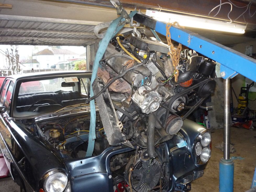 I haven't made a detailed study yet, but some stuff I've found out over the weekend: The 280SE engine bay is about 3cm narrower than the E300 donor car. This shouldn't be a big problem. The manual gearbox I intend to use is about 11cm shorter than the auto I'm removing. no problem in terms of mounting, but I'll need to extend the prop shaft to meet it. The rad from the donor is way too big. I'll wait to see what space is like with the new engine fitted before doing anything drastic, but I might have to go buy an aftermarket one. It looks like the steering box in the 280SE is enormous and might get in the way of the exhaust, but again, I'll see what its like with the engine fitted. I might even explore the possibility of installing the rack out of the E300 if it works out anyway handy as the old steering box is incontinent and making a mess of my garage floor. 
|
|
#17
06-09-2015, 10:51 AM
|
|||
|
|||
|
Warning: Don't follow the instructions in this post, it didn't work!
This is going to be a long post, I hope I've explained what's going on well enough for others to replicate it if they want to! I'm not sure what you call this plate, but this is the original plate which had the ring gear attached to it and sat behind the torque convertor. You might or might not be able to see there are 6 tabs protruding from it which whizz past a sensor which I guess is for an engine speed feed to the ECU rather than a crank position. 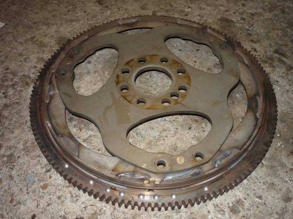 The ring with the tabs on it looks pretty crude, but it was obviously machined after being welded on to make it perfectly circular, at least on the outside! 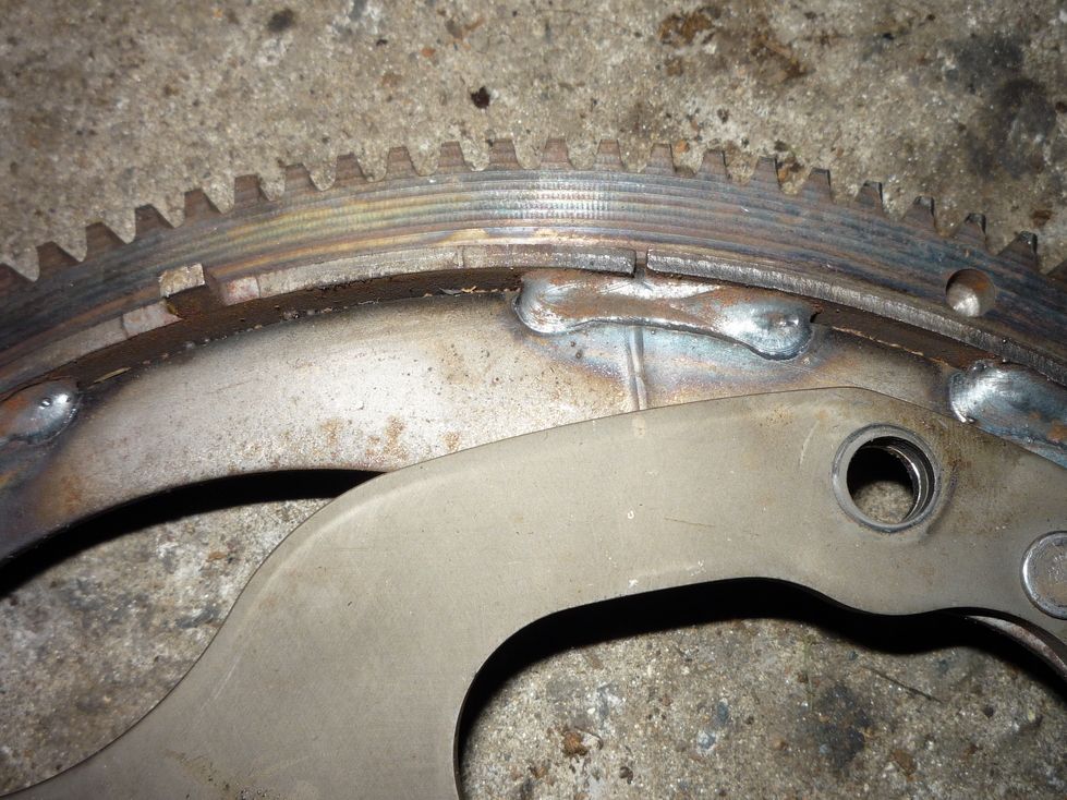 Anyhow, that bit is getting dumped as I'm changing to a manual gearbox. So, I bought one of this on a wing and a prayer. It was listed as a dual mass flywheel conversion kit for a Merc Sprinter van, 2.2CDI and others from 2002 to 2006: 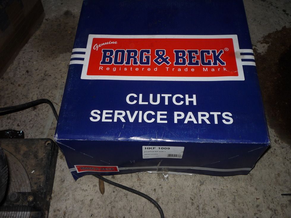 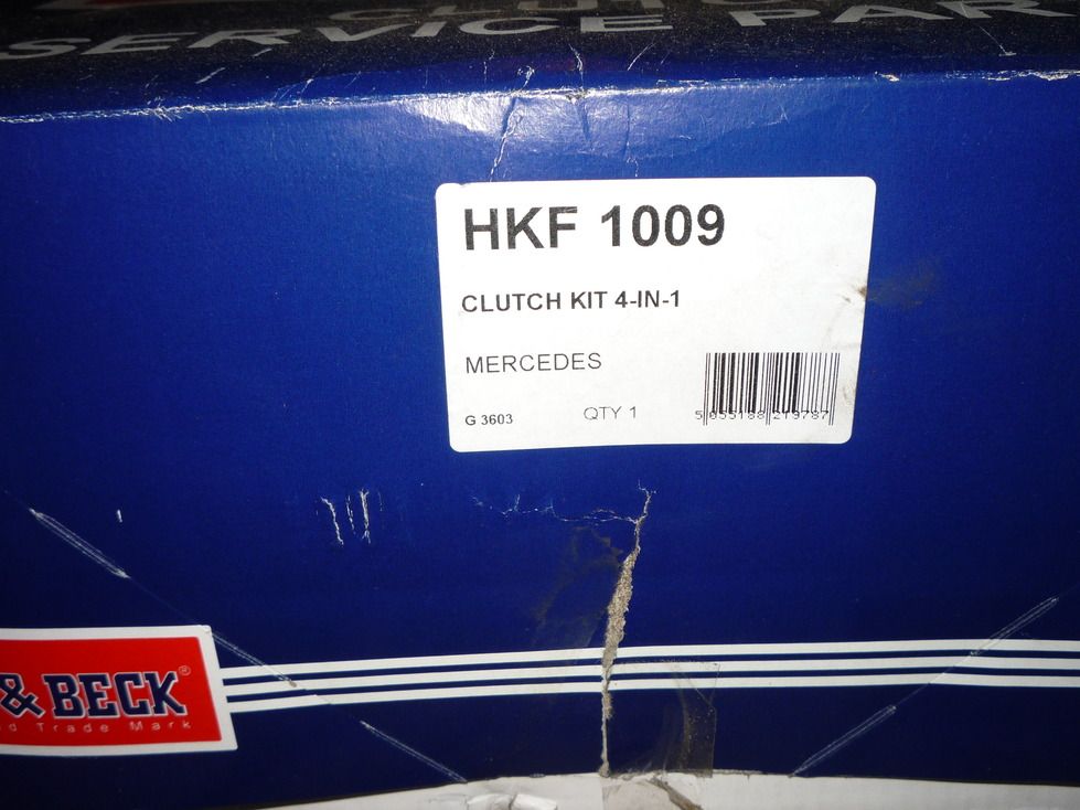 It contained all of these bits: 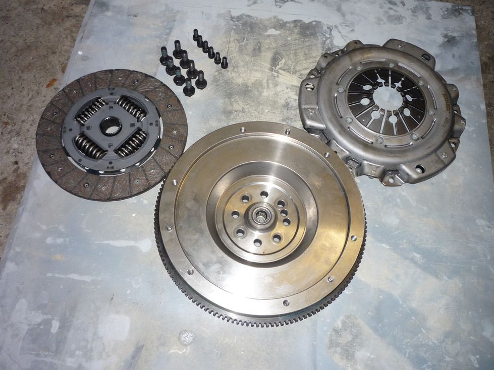 The first problem I encountered was that there is a protruding flange on the end of the crank shaft, and a corresponding recess in the flywheel. The flange was 11.2mm and the recess only 10mm. This meant that the flywheel could not be tightened right up against the end of the crank, so the crank shaft flange was duly ground back to be shorter than the recess in the back of the flywheel. 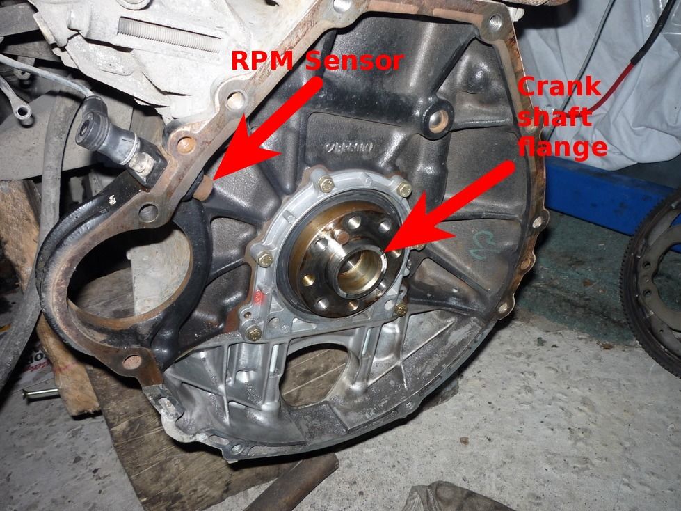 Problem number 2 is that the new flywheel is completely surrounded with ribs which, I can only suppose are used to generate a signal for the Merc Sprinter it was intended to be used in. 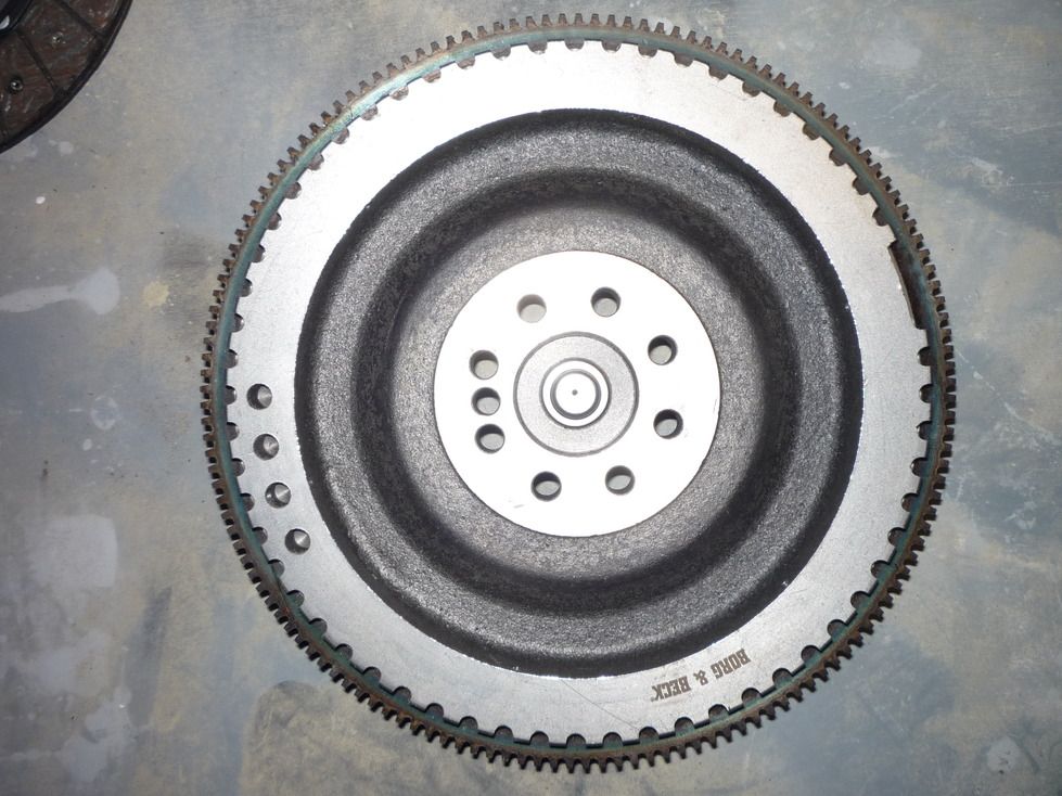 These ribs also slightly contact the sensor. Plan "A" was to machine away the ribs I don't need in order to leave 6 remaining, simulating what was in place before, I could then put a spacer behind the sensor so that it didnt stick out so far and wasn't hit by the remaining ribs. The main issues with plan "A" were that the ribs weren't in the same place on the flywheel as the tabs on the original item (I'm not absolutely sure that there isn't some kind of timing function along with RPM!), and that I would then need to have the flywheel balanced. I have a great engineering friend who came up with a far superior plan "B": We would drill the 6 'valleys' which correspond to the tabs we had removed, tap them and screw in bolts which would protrude above the existing ribs. We'd have to move the sensor even further out, but that's no big deal, and we wouldn't be disturbing the balance of the flywheel. So, to the implementation of plan "B". We marked the valleys which were to be drilled and tapped, then mounted the flywheel on the engine. We turned down a big bolt so that it matched the shaft size of the sensor and would fit snugly in the sensors mounting hole. We then drilled a hole down the centre of the bolt and poked the bolt into the sensor hole. Now, we had a guide which we could use to make sure the holes we drilled were directly beneath where the sensor would be. Here's the sensor fitment: 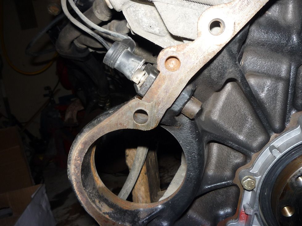 and the bolt we guntered into a tool: 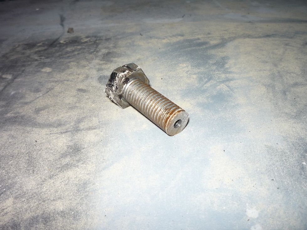 and some drilling underway: 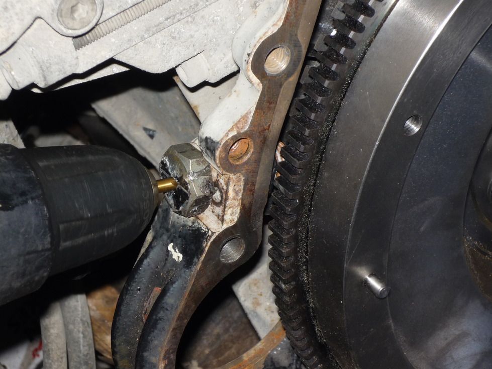 Here's a bolt inserted in the hole. I plan to get longer bolts, loctite them home and then remove the heads so that the part left sticking out proud of the ribs is closer to the 5.5mm of the tabs which were originally present. 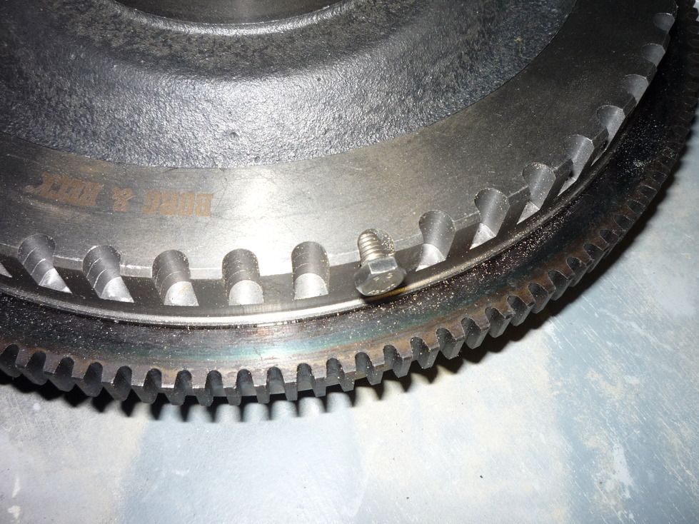 Aside from these alterations, Everything else seems to work out in terms of the position of the bearing which accepts the end of the spigot shaft, the position of the clutch friction plate in relation to the splined part of the spigot shaft, and the position of the pressure plate in relation to the release bearing/concentric slave culinder which is mounted in the gearbox. Happy days!
|
|
#18
03-21-2016, 11:53 AM
|
|||
|
|||
|
Well, plan B turned out to be a bit of a disaster! I attached the modified flywheel to the engine, and after setting the height of the RPM sensor so that my newly attached studs didn't hit it, we hooked up fuel and sealed up the oil & water pipes after a emptying a can of water in and seeing it flow across the floor! My self and a friend hoisted the engine up on the engine crane, hooked up a battery and hit ths starter. There was the usual click of the starter followed very closely by a thump, and the engine was locked solid!
It turns out that it isn't just the gear on the end of the starter which pos out to engage with the ring gear, most of the end of the starter comes with it! 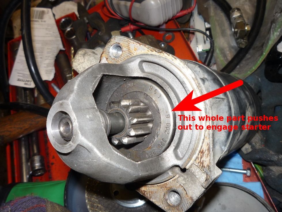 So, while the starter was engaged, the studs would whack straight into it and the flywheel do no more than 1/6 of a rotation. Plan A was re-hashed to become plan C and required some more extreme flywheel modification. The studs which we had inserted were removed with great difficulty. The Loctite we used had "Extra Strong" or something along those lines written on the bottle. It was amazing, the studs were locked solid after only an hour ror two! So much so that 2 of them broke off when trying to get them out! My friend set the flywheel up in his lathe and cut down all of the ribs from around the outer edge, then fitted new studs in the old holes and turned them down to the appropriate size. Here's how it was before: And after: 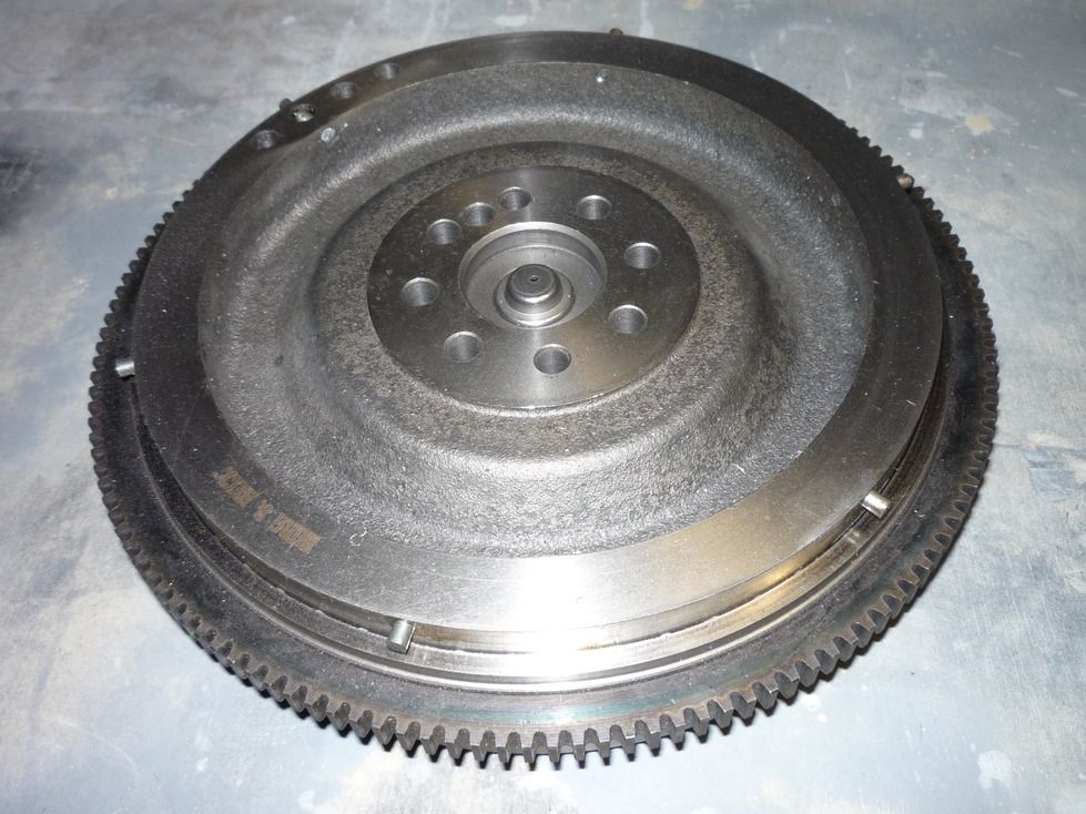 And a closeup: 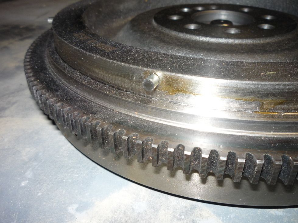 Now the flywheel is re-attached, the RPM sensor located appropriately and the engine runs suspended from the engine crane! It's a bit cold, and smoky as a reslt, but works fine. I don't know how to embed a video, but you can see the startup on youtube here. To say that I'm a happy camper would be an understatement! So, now on with the rest of the work: making engine mounting brackets, making clutch pedal assembly, adapting drive shaft, etc...
|
|
#19
07-11-2016, 11:07 AM
|
|||
|
|||
|
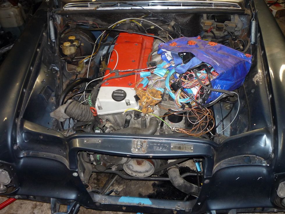
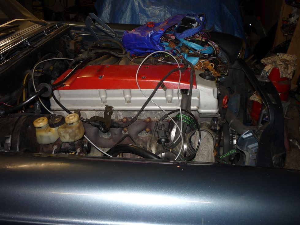
Well, here it is, the "new" engine in its new home. It's only sat there, but it fits in well. The engine bay looks a bit empty but will soon fill up with a battery, air box, computer box and screen washer bottle. the blue shopping bag contains the wiring harness for now!!
  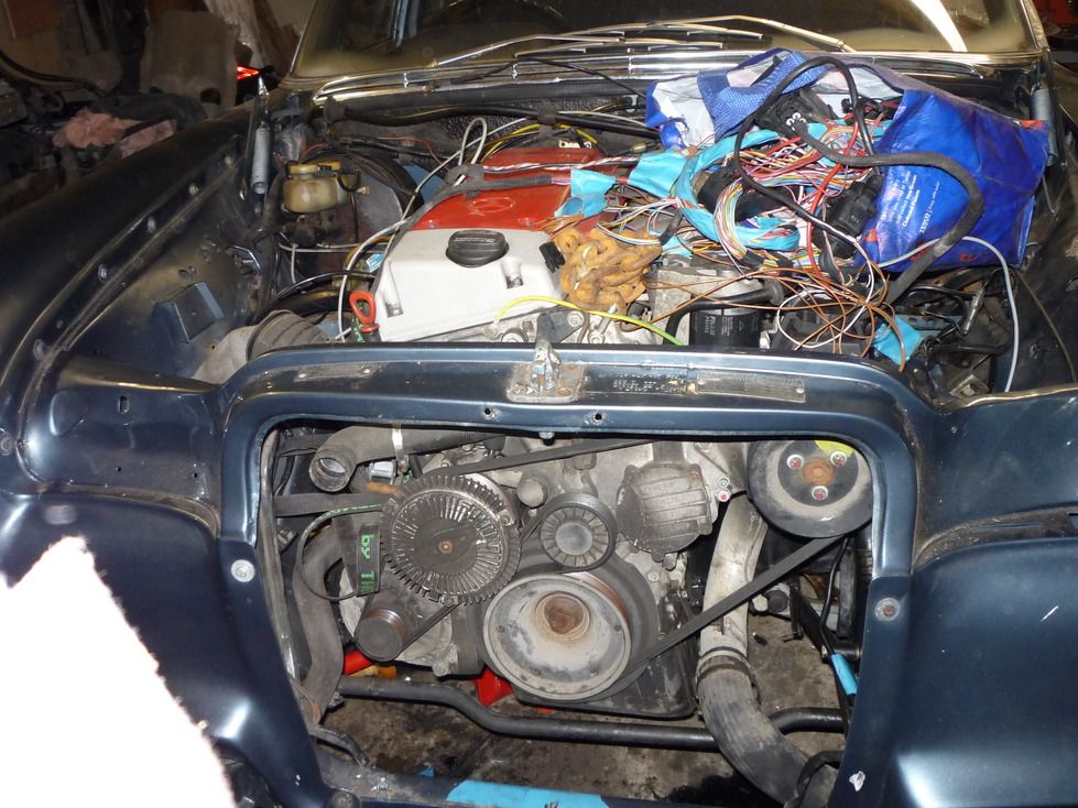 This intercooler pipe had to be sacrificed as it was sitting on the anti-roll bar, I'll just re-route it, or might even get away with squashing it a bit: 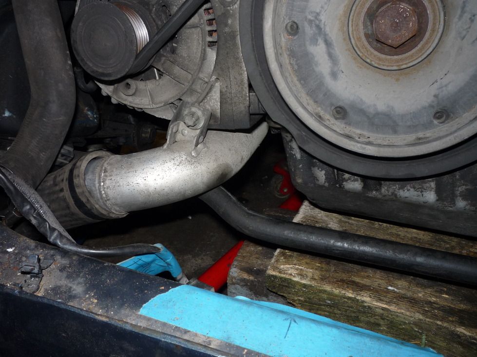 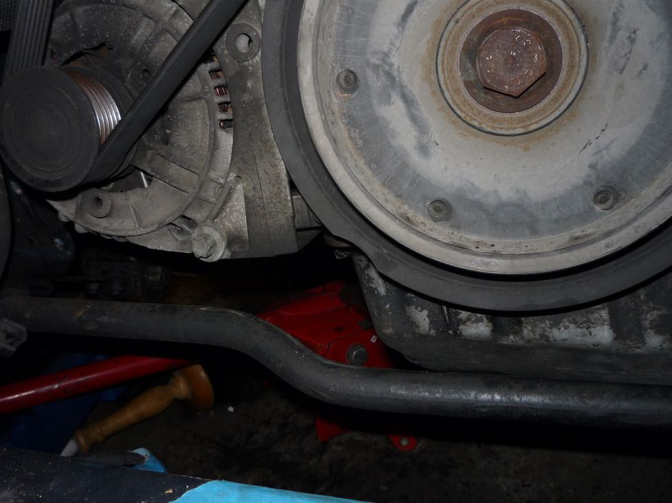 Lots of clearance between subframe and sump: 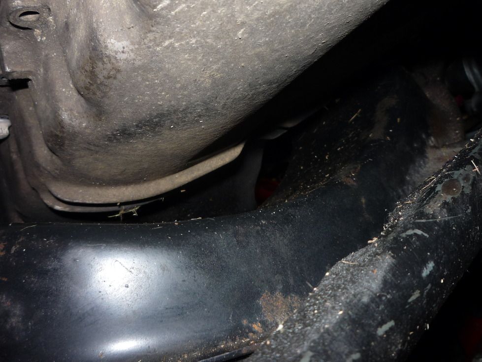 And the exhaust clears the steering box: 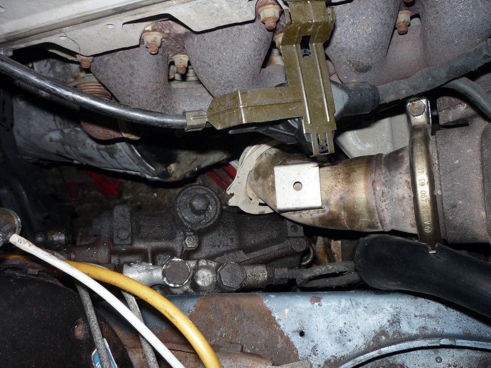 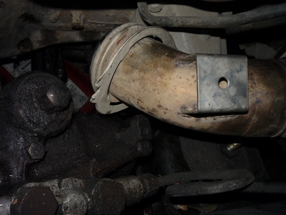 It's difficult to get a decent photo of it, but here's the attachment for the shifting mechanism on top of the gearbox. It's pretty tight to the top of the transmission tunnel. That long self-tapper is someone else's legacy! :roll: 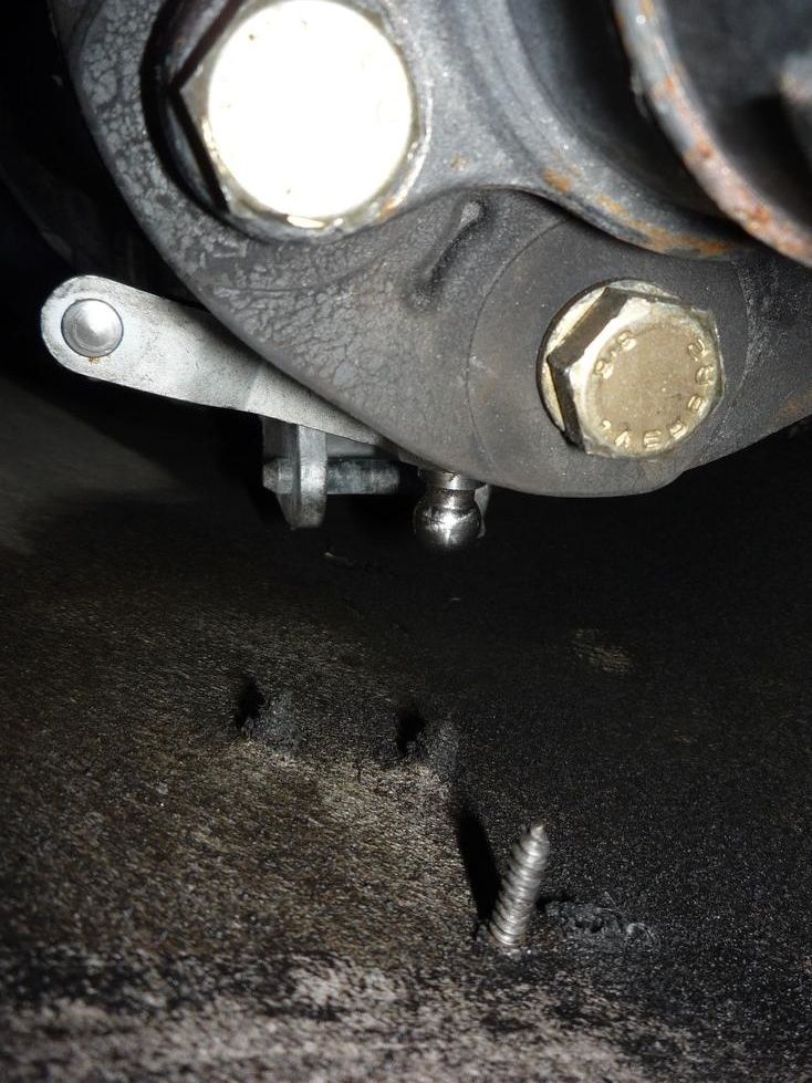 This photo shows the original V8 engine mount and the new, improved wooden version. 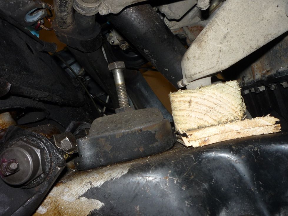
|
|
#20
07-23-2016, 08:50 AM
|
||||
|
||||
|
Wow, you've got more guts and patience than I do, that's for sure!
 Looking forward to seeing more.
__________________
It is a truism that almost any sect, cult, or religion will legislate its creed into law if it acquires the political power to do so. Robert A. Heinlein 09 Jetta TDI 1985 300D
|
|
#21
09-19-2016, 03:08 AM
|
|||
|
|||
|
Any progress?
Was the old V8 in good condition? What you do with it?
|
|
#22
10-10-2016, 11:15 AM
|
|||
|
|||
|
@W109Driver, I sent you a PM
Prop shaft sorted! The original shaft is used up to the carrier bearing, and it turned out that the splines on the shaft which came with the manual gearbox match it, so my very good friend just shortened the front section of the shaft which belongs to the gearbox. You can see how it was before and how it is now in the photos below. 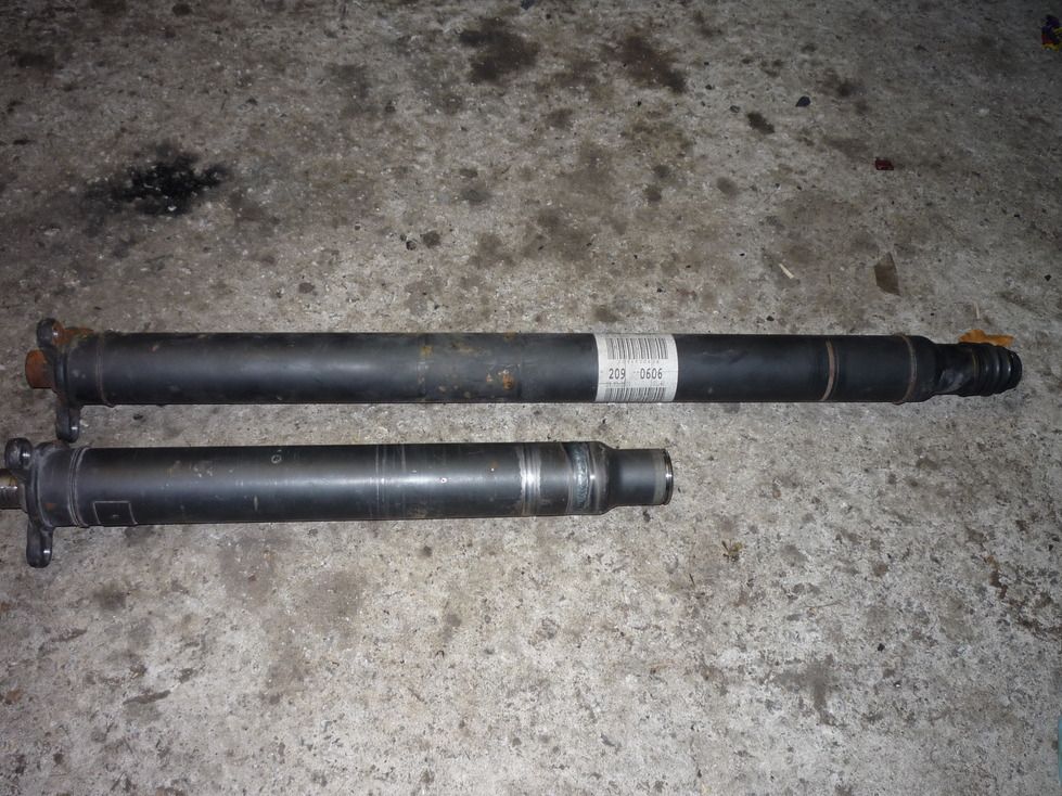 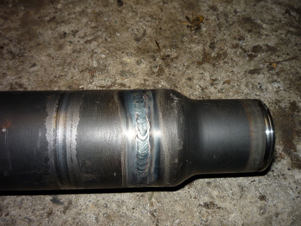 A few bits and pieces have been done on the car. I've made up some brackets to change the old lever/rod operated throttle to a cable one for the throttle position sensor. This is the new bracket to mount the sensor in the engine bay. 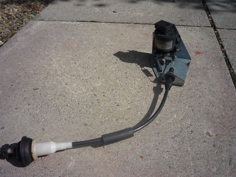 This bracket is fot the other end to hold the outer casing of the cable. Some rustiness in the bacground which will need to be dealt with! 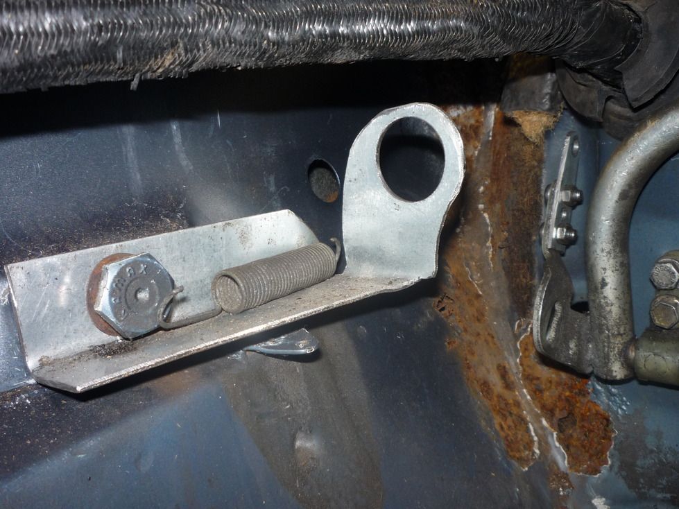 The clutch pedal and master cylinder are in. They are from the gearbox donor clk. The fluid line to the slave cylinder is routed on the inside, but I still have to sort it out on the outside. It connects with a length of flexi hose coming from the gearbox housing. 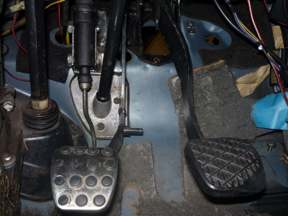 In other news, I've done some work to get the engine into its final position. My resourceful and very talented engineering friend made a mounting bracket for the gearbox. The OM606 engine is rotated to one side as standard so that is isn't so tall in an engine bay. Although the bell housing on my gearbox fits the engine crank case, the engine the gearbox was attached to mustn't have had the rotation because my gearbox now sits at an angle as you can see in this photo. The steering componenets are horizontal, the bottom of the gearbox is not! 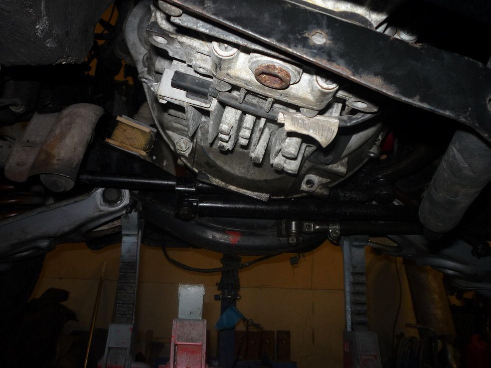 The gearbox bellhousing could be cut and rotated to straighten out the gearbox, but I'm going to just leave it as it is. It doesn't look like it will present any mechanical issues with the build. I'll be crossing my fingers a bit regarding internal lubrication.... Here you can see the new bracket before painting and in its final position in all its glory! 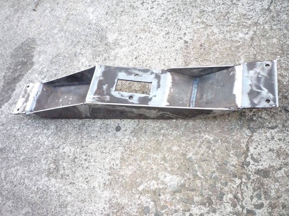 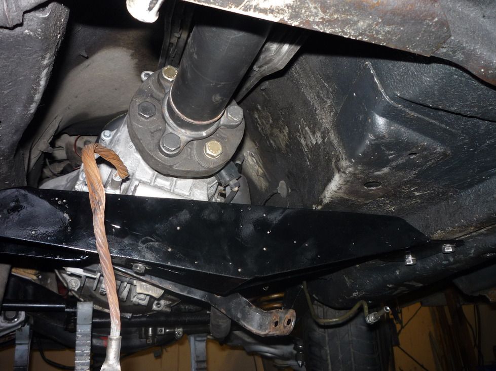 Once the rear of the gearbox was fixed in position, the engine was nudged around the place in order to get the drive shaft to line up correctly in the centre of the carrier bearing: 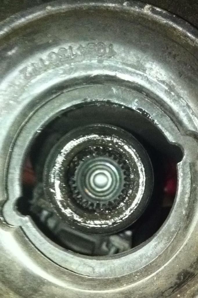 Now that that's done, it was a case of trying to make sure the engine ends up in the same spot once the new mounts are fitted. So, there are two dots on the sump which line up with two ends of a piece of TIG wire. Once the new mounts are made, the engine should settle back into the same spot. That's the plan anyhow! 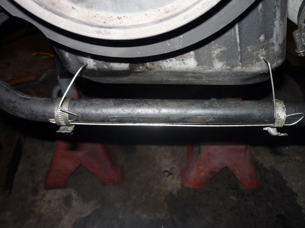 That's it, once the engine mounts arrive, it'll be a matter of figuring out how much they will compress under the weight of the engine, and making a mounting plates to suit.
|
|
#23
10-11-2016, 08:29 PM
|
||||
|
||||
|
Looks like a nicely crafted and cool project, will make for a fun daily.
__________________
97 e300d, 78 300Dt, 95 E300d, 94 E320 estate
|
|
#24
10-20-2016, 03:10 PM
|
|||
|
|||
|
This should be good
Just wanted to utter a few words of encouragement....
I am glad to see you taking on such an incredible feat. Should be a great driver, with the best of both worlds (classic and modern). I have a 1970 280S and the motor died 10 years ago, so it's been parked ever since, waiting to be resurrected, but to be honest I was never all that impressed with the old 6-banger and its finicky carb's and high fuel consumption. I had considered putting a 5 cylinder turbo diesel from a W123/126 in it, but now that I see your build, I think I'll follow suit. What a great idea! Can't wait to see how it all turns out....
|
|
#25
05-01-2017, 06:33 PM
|
|||
|
|||
|
My 6 speed gearbox is from a 2004 CLK. The gear shifter is attached to it by a long aluminium U-shaped bracket which attaches to the rear/top of the gearbox and to the shifter mechanism. It's relatively straight-forward to re-use this whole setup except that I'm a little tight for space, and, more importantly, my gearbox is rotated in relation to the horizontal plane the gear stick should work on. So, if kept standard, the gear lever would be pointing out the driver window instead of straight up. Hopefully the photos will help explain.
The plan ended up with chopping the mounting point off the bracket and welding it back on at an angle. The effect being that the whole brakcet and gear shifter unit is rotated back into the horizontal plane. Since the top of the gearbox is leaning towards the driver's side of the car, but the shifter will be mounted in the middle of the transmission tunnel, it will have to operate at a slight angle rather than straight front to back, but I reckon I'll get used to that pretty quickly. So, photos: Here's the whole assembly: 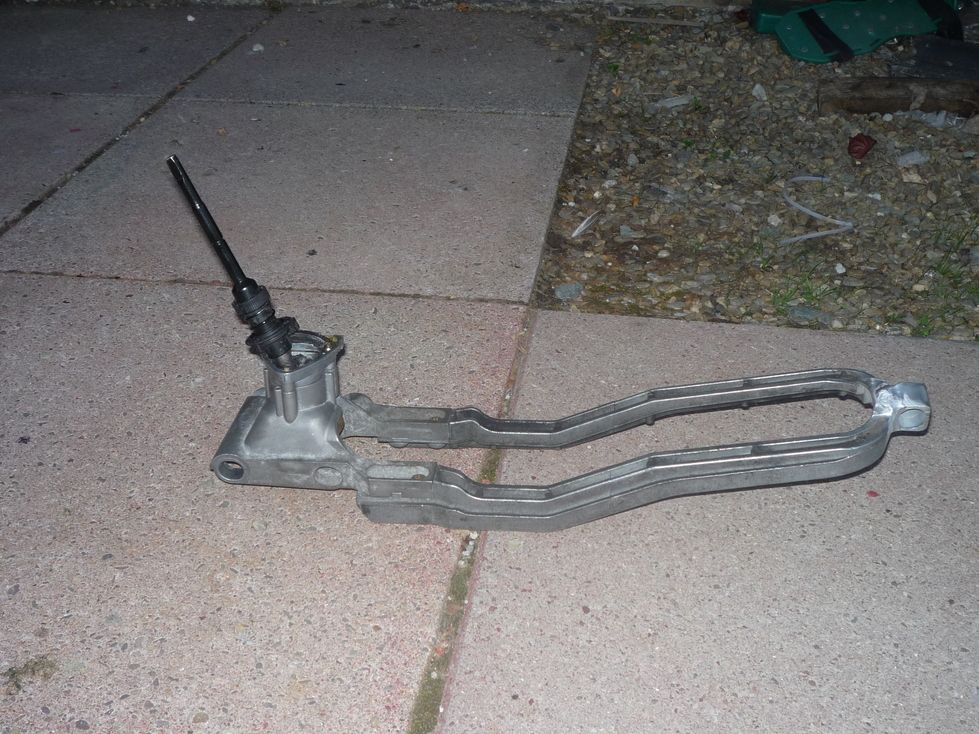 And this is how it conects to the gearbox. There's a rubber bush which goes in the bracket, and a pin runs through it to secure it all to the gearbox. 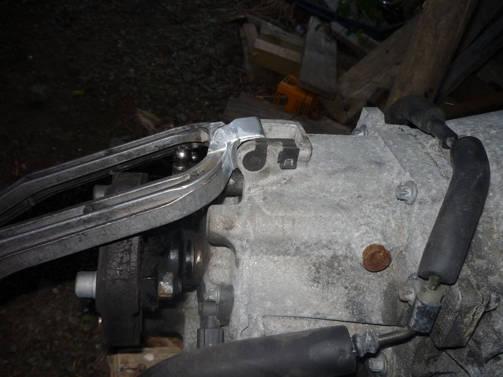 Here you can see the angle which has been introduced. 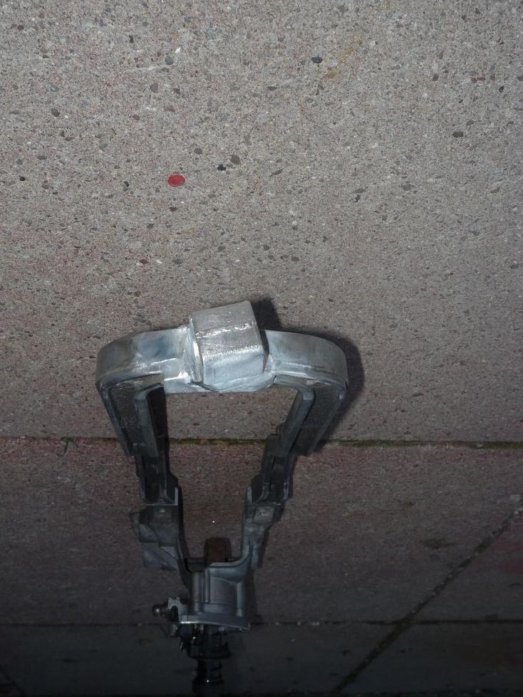 A little angle grinder action been going on to make a spot for the gear lever. It'll get bigger before it gets smaller, it's too far forward by a couple of inches! 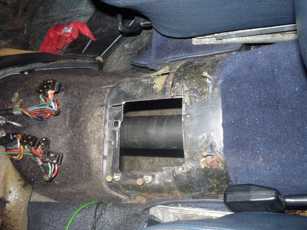
|
 |
| Bookmarks |
|
|


 Linear Mode


