

|
|
|
|
|
|
|||||||
 |
|
|
LinkBack | Thread Tools | Display Modes |
|
#1
 06-14-2009, 02:54 AM
|
||||
|
||||
|
Time for another pictorial: How to change a steering wheel contact ring.
This pictorial is on how to replace a steering wheel contact ring. I am replacing the standard contact ring with one removed from a 300E 4MATIC. The 4MATIC contact ring (p/n 140-464-28-28) is different from the standard contact ring (p/n 140-464-27-20) in that it has small magnets embedded in plastic surrounding the four visible copper rings. The magnets work with the 4MATIC computer steering sensor input. Other than the presence of the magnets the contact ring it is the same as any other and may even be used with a non-4MATIC vehicle.
This is not an instruction on how to remove the steering wheel from the vehicle or the airbag from the steering wheel. This picture shows the standard contact ring installed in the steerting wheel. The RED line points to the two airbag rings and the BLUE line points to the two horn rings. This is the ring I will be replacing. 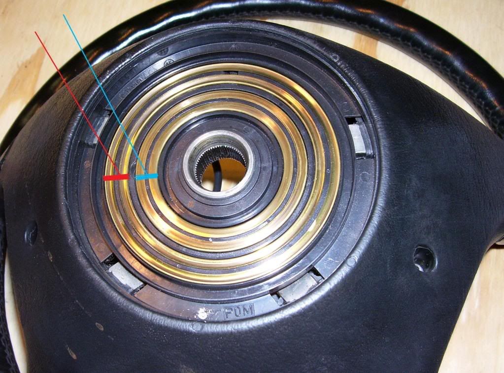 This picture is of the 4MATIC contact ring, with the GREEN line points to the magnet ring, the RED line points to the two airbag rings, and the BLUE line points to the two horn rings. Note the word 4MATIC on the lower left of the ring in the PURPLE circle. Again, this instruction will work for a non-4MATIC contact ring and a 4MATIC contact ring will work with a non-4MATIC vehicle. 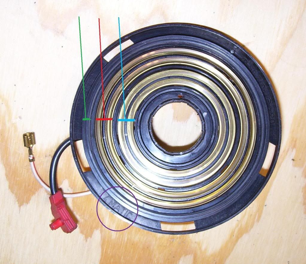 This picture is of the underside of the 4MATIC contact ring. In this picture you can see the little magnets at the GREEN lines. 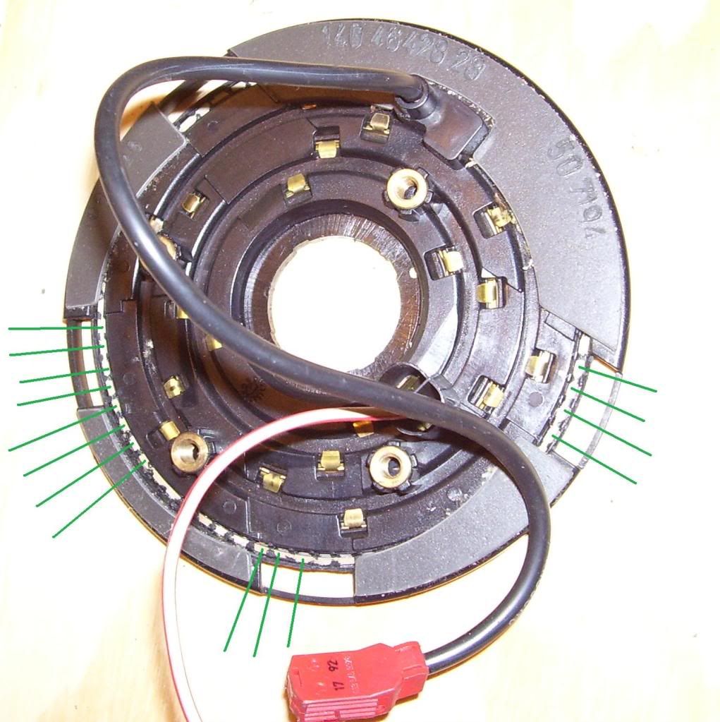 Here is the front of the steering wheel off the vehicle with the airbag already removed. 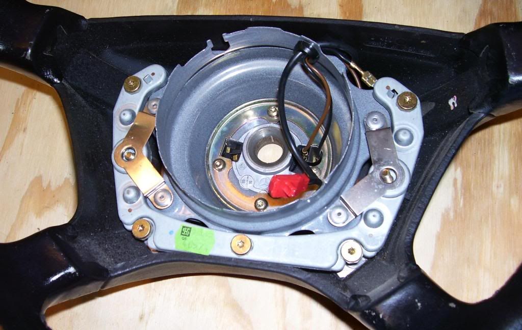 Begin by removing the four torx screws in the inner portion of the steering wheel with a T-25 torx tool. 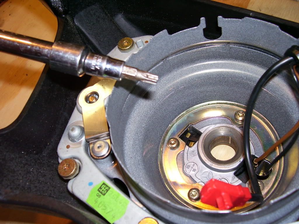 Next gently push the wire saver grommet out of the wire pass through hole from inside to out (see PURPLE circle in next picture). It is split down the side. Remove it from the wires. 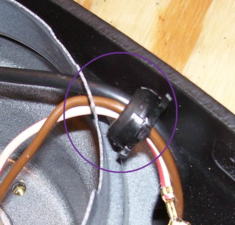 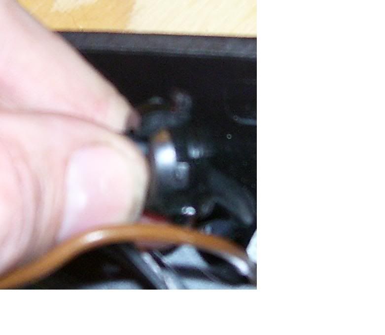 Next gently remove the two wires for the horn, one on the inside and one on the outside of the center (see RED circles). Pull the loose ends of these two wires through the pass-through hole - one will come in and the other will go out (see PURPLE circle). Once the horn wires are out of the hole there will be enough room to pull the airbag connection wire out as well - so do it. 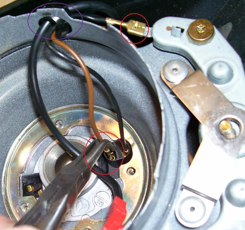 Now remove the four outer torx screws, again with a T-25 torx tool (see BLUE circles). Note that you do not need to remove the fifth torx screw at the bottom center. 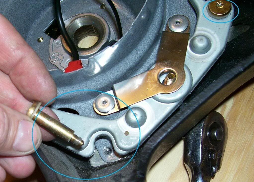 Next pull the inner workings out. Note that the two upper corner torx screws are still in place in the first picture, but rest assured they have been loosened. 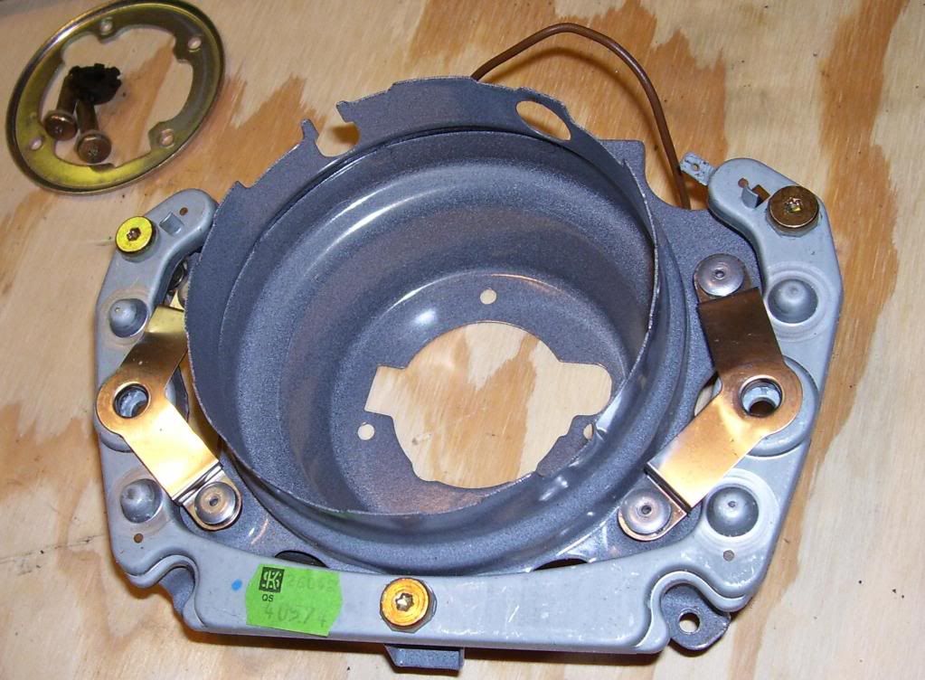 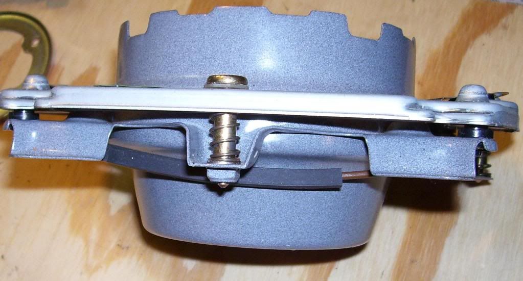  Here is what you should have left of the steering wheel at this point. Note that the two torx screws (T-30) that secure the airbag have remained in the steering wheel. These are loose so set them aside for now; be careful not to loose them (see WHITE circles). 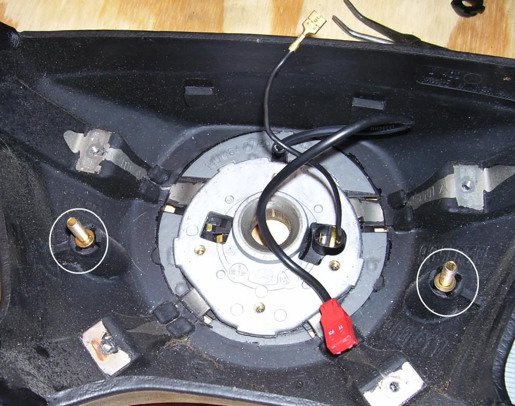 Now VERY gently insert a wedge between the contact ring and the steering wheel cover and loosen the covering from the contact ring all the way around. 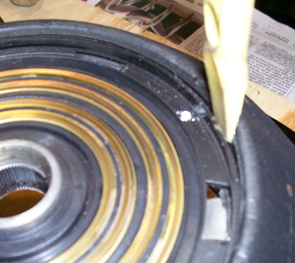 Once the contact ring is loose it should look like this: 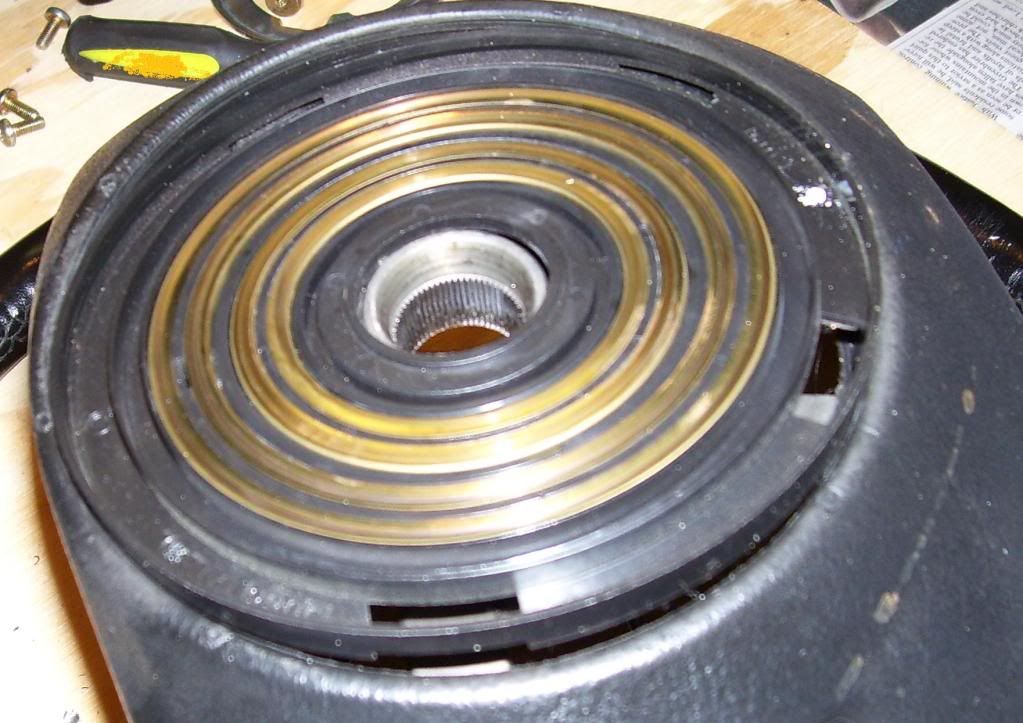 Remove the old contact ring, but take note of the wire placement. 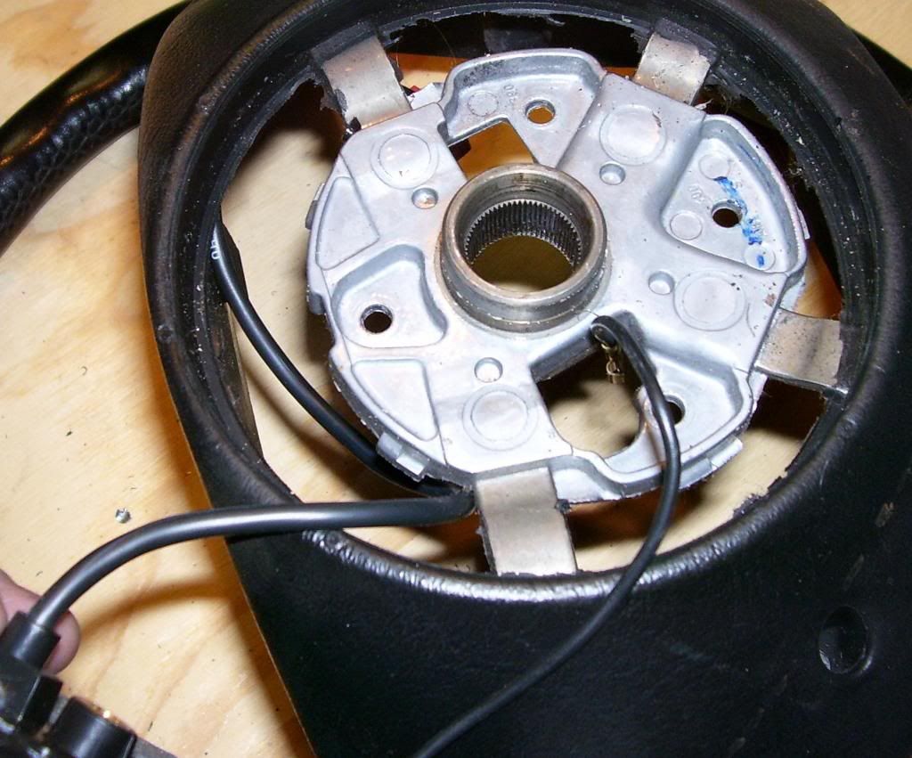 Installation is pretty much the reverse. There are just a few points worth mentioning. The four contact rings screw holes line up only one way with the steering wheel. Make sure they are lined up prior to assembling beyond the contact ring. 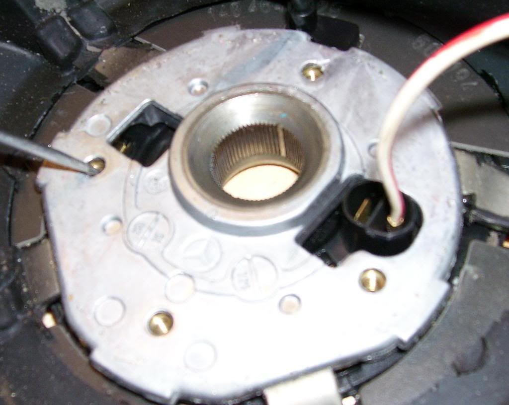 There are two tabs at the inside top of the steering wheel cover (see PURPLE circles). 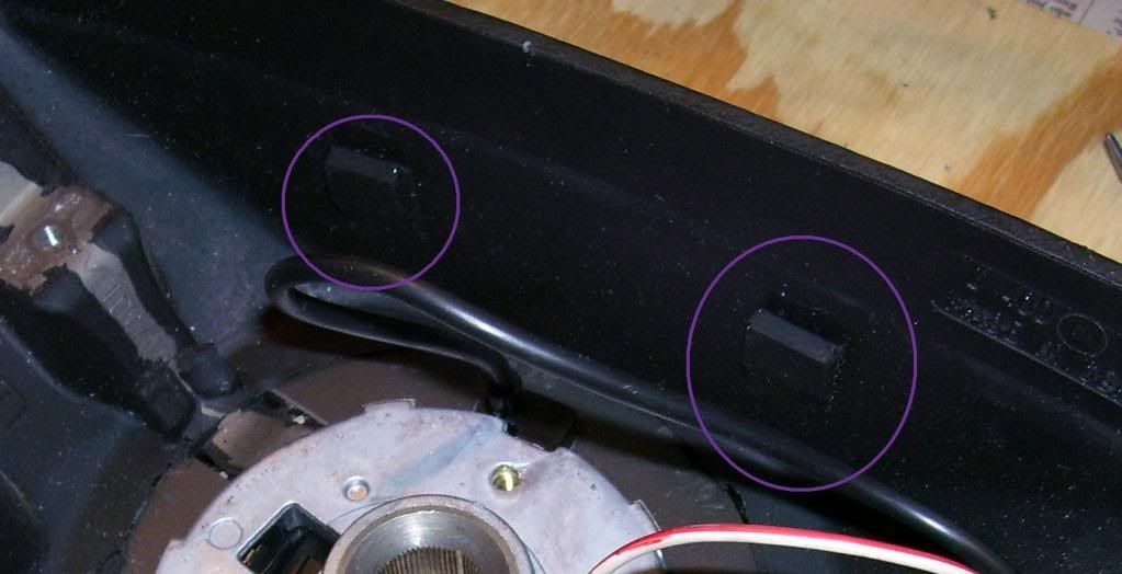 These two tabs are held in place by the center piece when it is installed (see one of two in PURPLE circle). 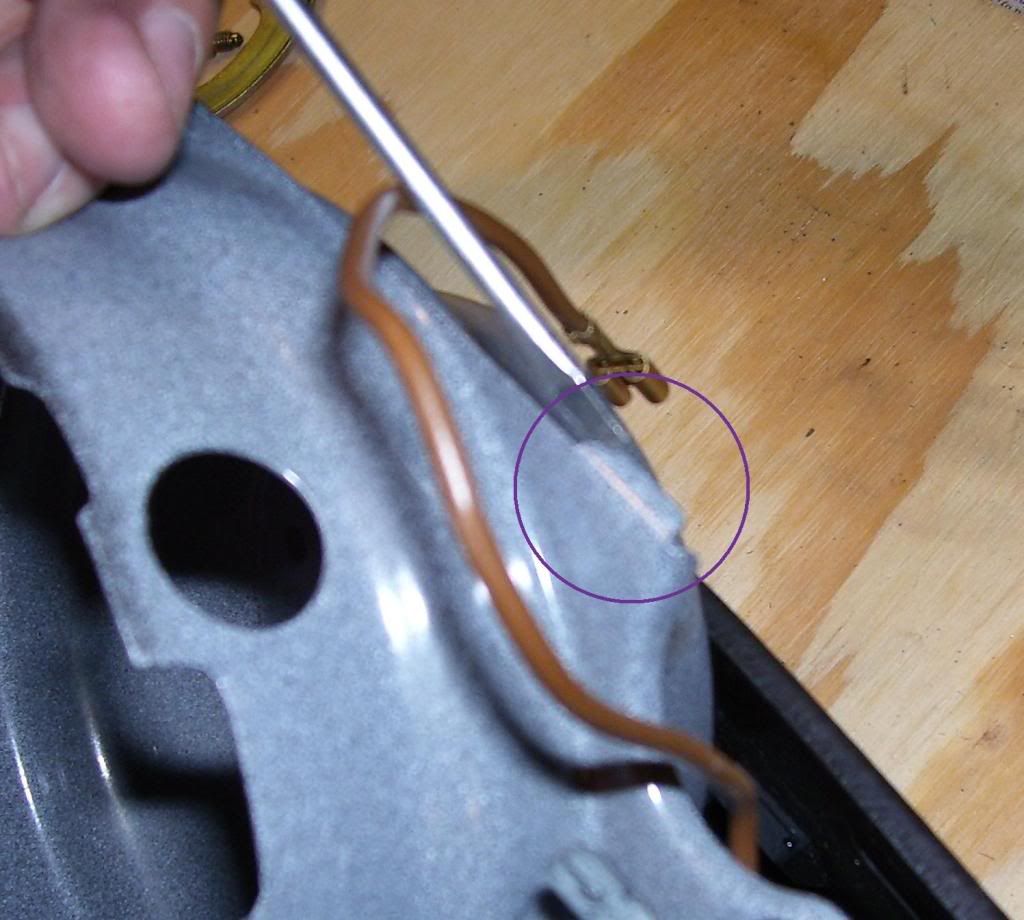 Be sure not to forget the torx screws for the airbag (see ORANGE circle). I held them in place temporarily with some tape while I made sure the wires were all routed, and the two retaining tabs were secured properly. 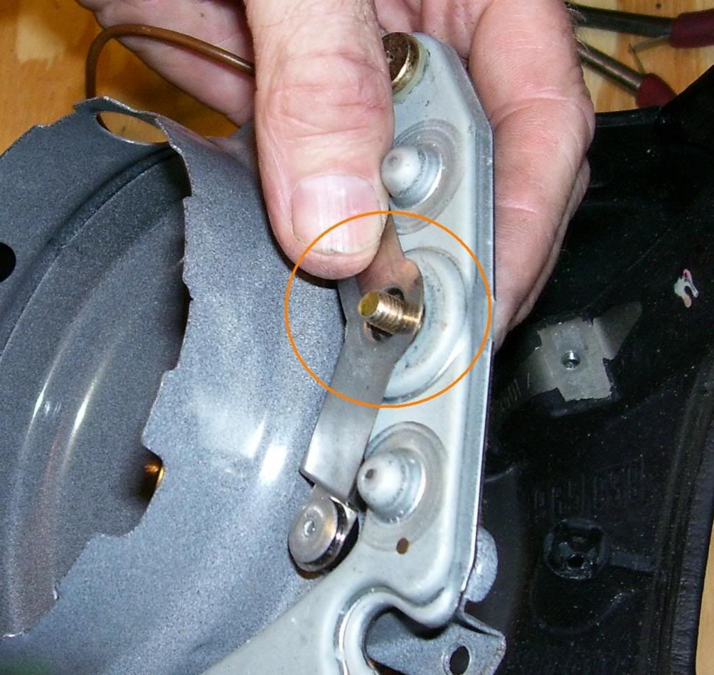 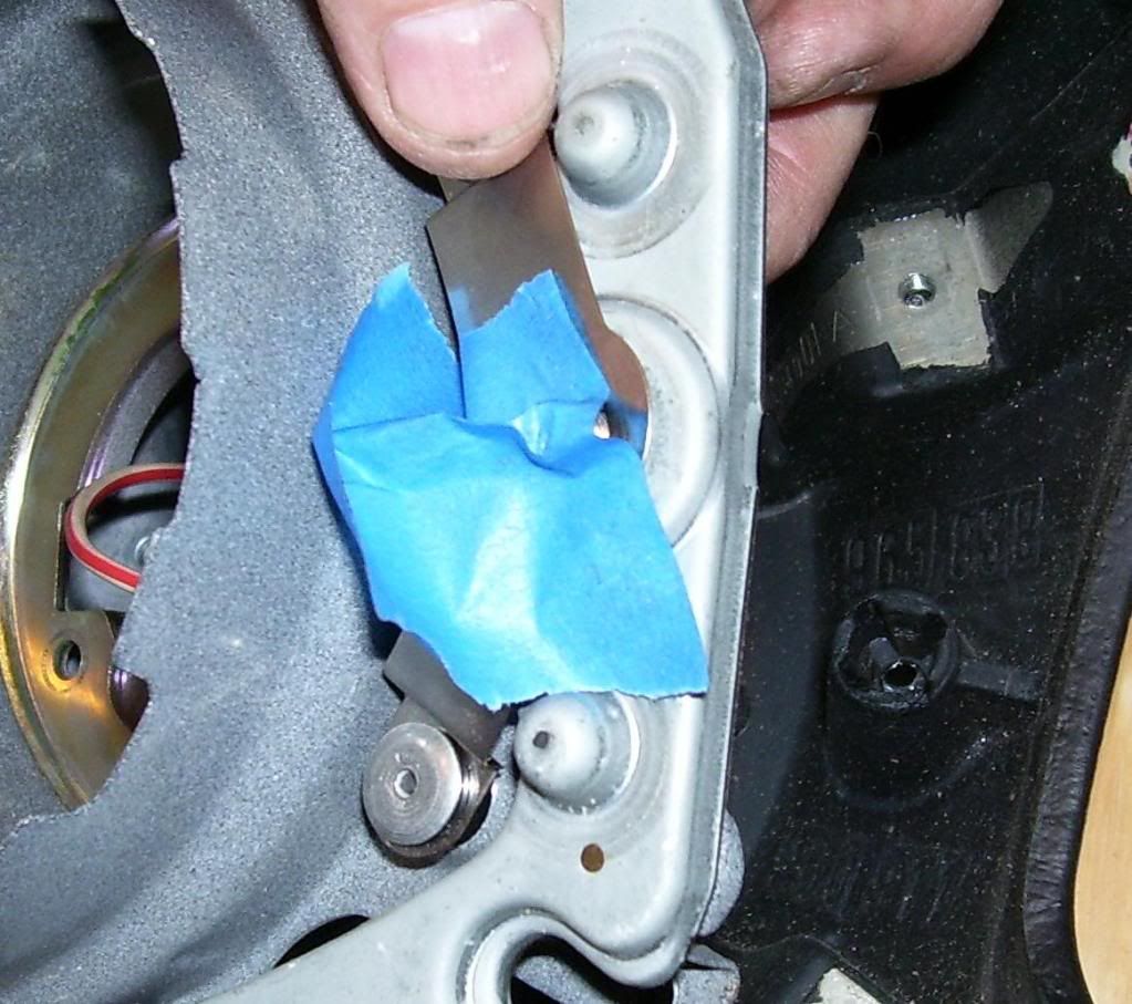 Presto Chango - The finished product is now ready to install on my 4MATIC. 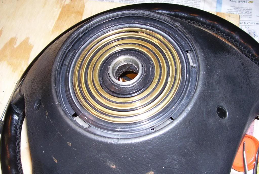
__________________
http://i284.photobucket.com/albums/l...aman/Fleet.jpg Peach Parts W124.128 User Group. 80 280SL 85 300SD 87 300TD 92 300D 2.5 Turbo 92 300TE 4Matic Last edited by pwogaman; 06-26-2009 at 11:07 AM. 
|
|
#2
07-08-2009, 01:34 PM
|
||||
|
||||
|
__________________
Bill Wood - Retired Webmaster My Personal Website 1998 Mercedes E430 2010 Toyota Sequoia My Photo Albums
|
|
| Bookmarks |
|
|


 Linear Mode


