Manually Controlling Center and Footwell Vents
on the 1987 300TD (W124)
by zebellis
01/26/11
Since buying our first Mercedes a year ago - 87 300TD - I've gotten used to the automatic climate control system… for the most part. I had originally started a thread over here about changing nearly every aspect of the ACC, but I think the only two things I want to modify at this point is control over the center and footwell vents, and maybe someday getting control over the blower speed. The primary reason for wanting control over the vents is that in heating mode, by design, the center vents do not operate. When my hands are cold, I can warm one up with the side dash vent, but not the other hand. Turning on the center vent solves this problem. Also, sometimes the heat on my feet is too much.
Here's a write-up on how I tackled the first project - install a switch to manually choose between the center vent, the footwell vents, or both.
First, a little background information wouldn't hurt...
There are three ways in which air enters the cabin: defroster vents, dash vents, and footwell vents. Behind each vent is a flap that is controlled by a vacuum pod. The defroster vent flap and the side dash vent flaps are opened by a shared vacuum pod. The center vent flap is opened by its own vacuum pod, and the footwell vent flaps are opened by one (since 9/86) or two (before 9/86) vacuum pods. Since the side vents operate in unison with the defroster, we'll leave them and focus our attention on only the center and footwell vents.
Every flap in the car either opens or closes when its respective vacuum pod gets vacuum suction applied via a vacuum hose. Both the center and footwell flaps are normally closed when their vacuum pod doesn't have a vacuum. When the Automatic Climate Control (ACC) unit wants to open one of these flaps, it switches on one of the solenoids in the switchover valve block (Y7) to direct vacuum to a specific vacuum pod. When the ACC unit wants to close one of those flaps, the respective solenoid in Y7 is de-energized and vacuum suction is removed from that vacuum pod. At this point, the valve on Y7 is switched back to an open port on the back of the unit to allow air to flow into the vacuum hose and back into the pod. This is important because without this open port, the vacuum pod would stay "activated", and it wouldn't be able to return to it's normal position (closed in the case of the center and footwell pods).
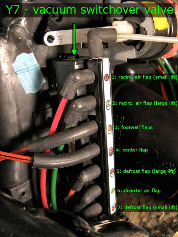
Y7 has a valve on the top where vacuum is always present (sucking, if you will). There are 7 valves on its side that go to 5 different pods. (Two of the pods, the defroster and fresh air pods, each get two hoses going to them to allow for each pod to have two activated states. Applying vacuum to the first valve on the pod makes it partially open a flap, apply vacuum to the second valve on the pod and it will fully open that flap.) Each of the valves on the side of Y7 have a restrictive plug in them to slow down the flow of air. This creates a delay in the opening and closing of each pod which makes the process of opening and closing flaps more gradual, less loud, and probably extends the life of the vacuum pods. Each valve has a different amount of restriction, and on my unit valve number 2 had no restrictive plug (not sure if it use to or not). The back of Y7 contains all the open ports for each valve. When the solenoid for a valve is de-energized, that valve is open to one of these ports for air to flow through to the vacuum pod allowing its internal spring to return it to its normal state.

The ACC unit is programmed to send heat primarily through the defrost vents and the footwell vents, keeping the center vents closed. It is programmed to send cold air through the defrost vents and the center vent, keeping the footwell vents closed. If we want to have manual control over the opening and closing of the center and footwell flaps, then we need to make sure we set our mod up to work in both the summer and winter. Fortunately it's pretty easy to do.
Since the ACC unit always has one of the two flaps open (with the exception of defrost mode), we can combine the two valves that govern the center and footwell pods to give us one vacuum source that's always on when we're in one of the non-defrost modes, and regardless of whether we're heating or cooling. Then we'll split this new combined vacuum source to two separate switchover valves that will connect to the center vacuum pod and the footwell vacuum pod. (I'll call these new switchover valves vacuum relays to keep things clear.) We'll wire these vacuum relays to a new switch on the console. In order to use a stock Mercedes switch with three positions, we'll need to have our vacuum relays perform the opposite function than Y7 does. Namely, when the vacuum relays are not energized, vacuum flows to the pods activating (opening) them. When the vacuum relays are energized, vacuum is blocked, and the pods are connected to an open (non-vacuum) port.
The switch will be a rocker switch with three positions:
- up - center vents only (footwell flaps closed, footwell vacuum relay energized)
- middle - center and footwell (both vacuum relays de-energized)
- down - footwell vents only (center flap closed, center vacuum relays energized)
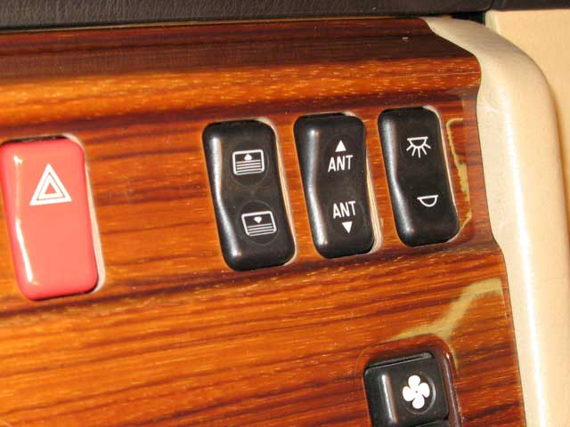
We need a switch that will stay in each of the three positions. The way to connect the hoses to our vacuum relays and the way to wire them to the switch will depend entirely on what switch you will use. I looked for a switch with pictures that could depict upper and lower vents, and found one close enough, but it wasn't the right type. It was a rear window screen switch (124-821-04-51), but the rocker didn't stay in the up or down position, and the caps are too integrated with the inside mechanisms to move it to another switch.
 If anyone can figure out how to modify this switch, that'd be awesome! Other switch suggestions are welcome too.
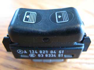
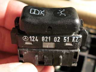
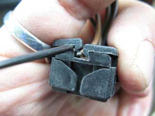
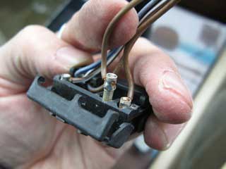
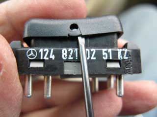
There are probably more options than I found at a junk yard covered in several feet of snow (I couldn't get into half the cars), but I settled on the interior dome lamp switch (124-821-02-51).
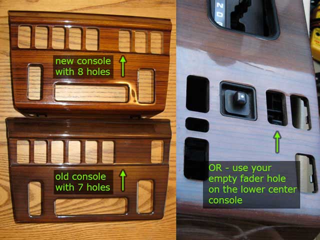
In order to make room for this switch, I found a console panel that matches my interior, but with one extra switch opening. If you have installed a new stereo that doesn't use the factory fader, you could use the space where the fader switch is - I'll cover both options.
You will need:
- two vacuum relays (vacuum switchover valves) 0015407097, $20 each or less from junk yard - many models have at least two of them
- wiring harness for the vacuum relays, or four butt connectors that'll fit over the pins
- 5' of vacuum hose - I used .170" ID polyethylene tubing which fits really well over the valves on the vacuum relays
- two 3/16" hose couplers
- two 3/16" hose three-way couplers, wyes are better than tees, or you could use one four-way coupler
- two check valves (pet stores have nice small ones)
- an ON-OFF-ON SPST rocker switch for the dash, with wiring harness - I used an interior dome lamp switch (124-821-02-51), but others will do
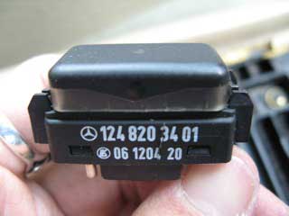
- any extra junk switch and harness for an extra pin and socket to properly rewire the above switch to illuminate with the other switches at night - find one where the pin is easy to remove (124-820-34-01 works great)
- several feet of wire, preferably a few different colors
- electrical connectors (I used what I had, you may want to do things differently, so I won't list every single one)
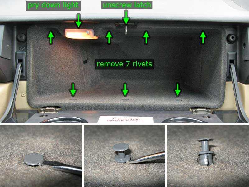
1) Remove the glove box liner. There are 7 plastic rivets along the inside of the glove box (4 on top, 3 on bottom). Pry up the rivet with a flathead screwdriver about a half inch. You will then be able to remove the two-piece rivet. Unscrew the latch at the top.
2) Pry down the front of the light cover and pull it out to disconnect the clip. Pull down on the top center of the glove box liner about 1/2" then pull out.
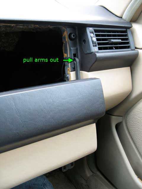
3) Next unscrew the glove box door hinges. You can then remove the arms from the dash by letting the door hang down (in its upright position, like when it's closed, only dangling down below the opening), then pull the arms out of the rubber opening. You can alternatively pry out the rubber grommets to make more room for getting the arms out.
4) Locate the vacuum switchover valve (Y7) at the left of the glove box opening, on the right (passenger) side of the air box.
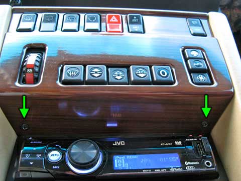
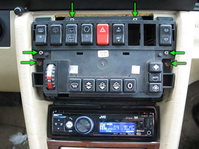
5) Remove the center console panel by unscrewing the two screws directly above the stereo. Gently pull outward from the bottom of the panel and it will hinge at the top until you can pull the panel off.
6) Unscrew the ACC unit. There are two large screws and four smaller ones. Pull the ACC unit out and leave it hanging to the driver's side. You can keep it plugged in.

7) If you are using the fader switch hole for your new switch, then you'll need to remove the lower center console.
8) Pry back the carpet under the armrest with a screwdriver being careful not to use the wood panel as leverage - as it will likely chip or crack.
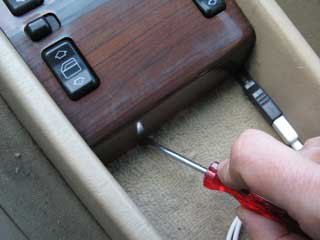
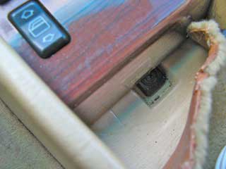
9) Unscrew the exposed screw.
Put the shifter into reverse or drive (with the car off!).
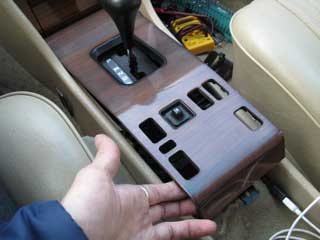
Lift up on the panel and it will hinge at the front until you can pull the panel off.
10) Remove the fader switch. If you are using this option, then it's likely that you've already been messing with these wires to access the speaker wires.
In any case, you need to pull the wires down through the bracket holding the window switches, and out into the open area near the shifter to get them out of the way.
This may involve cutting or unsoldering the wires.
Do this at your own risk! I did this last year when I replaced my stereo, so I don't have any photos.
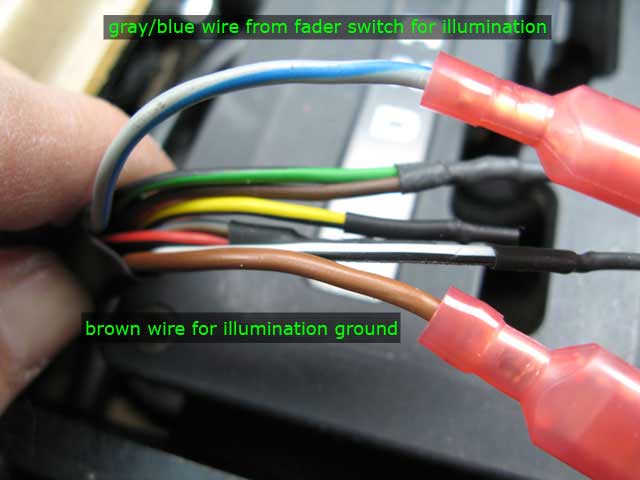
The gray/blue wire that powers the light in the switch will come in handy with our new switch.
11) In the back of the glove box compartment is a group of wires that lead to the glove box light.
Carefully remove a few inches of the sheath.
Tap into one of the black and yellow striped wires to get power for our vacuum relays.
Run the wire under the vacuum switchover valve (Y7) and through to the center console compartment where you will be installing your switch. 4-5 feet of wire should be enough.
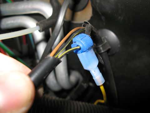
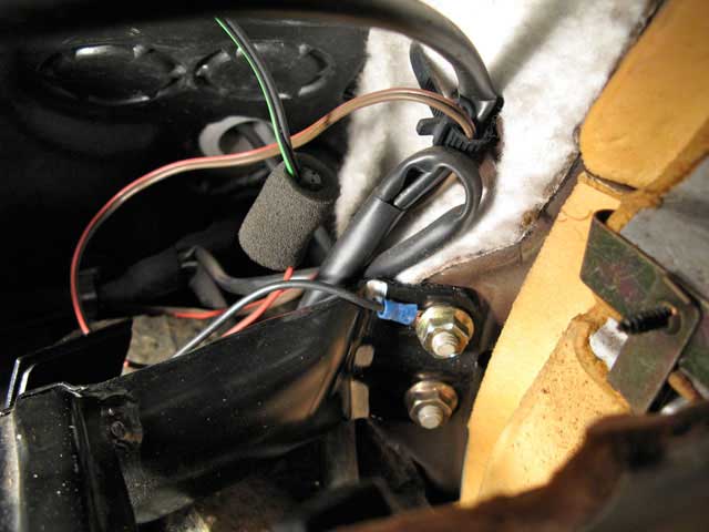
12) You could use the brown wire on the lead to the glove box light for ground, but I chose to run a new wire to the bolt holding the black crossmember to the frame.
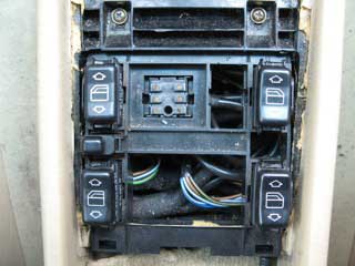
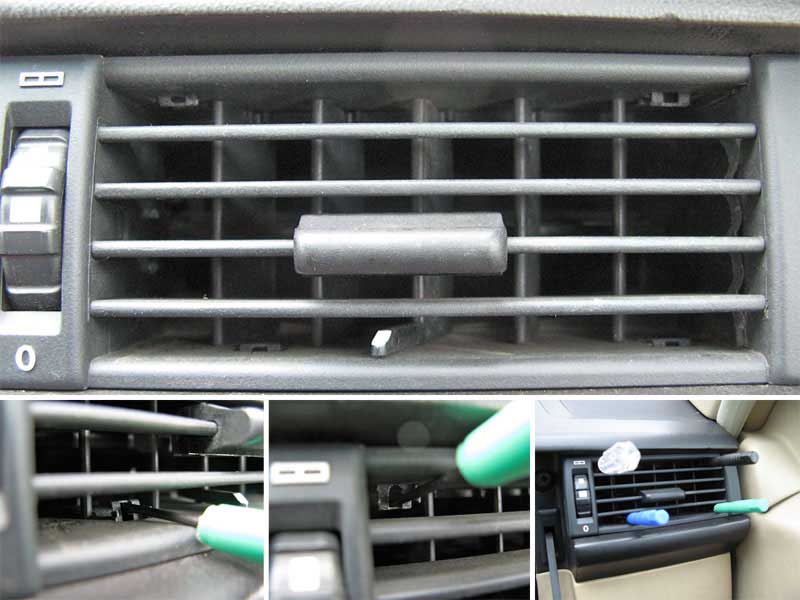
If you want to do it the hard way (like I did), you'll need to remove the passenger side vent, and move the large air duct out of the way (it's actually not that hard).
The vent has four spring tabs holding it in place.
Using four small screwdrivers or coat hanger wire, pry the bottom spring tabs up and the top ones down enough to release pressure on the surrounding dash.
The vent should slide out, but it may take some persuasion. Carefully disconnect the illumination bulb.
View through the passenger side vent opening
13) The ground wire only needs to be long enough to reach into the center of the glove box opening, but with plenty of slack.
This is where our new vacuum relays will go.
There's plenty of space between the crossmember and the side vent air duct to tuck the relays so we can get the glove box back in.
You'll need to split this wire off so that we can make two ground connections - one on each of the vacuum relays.
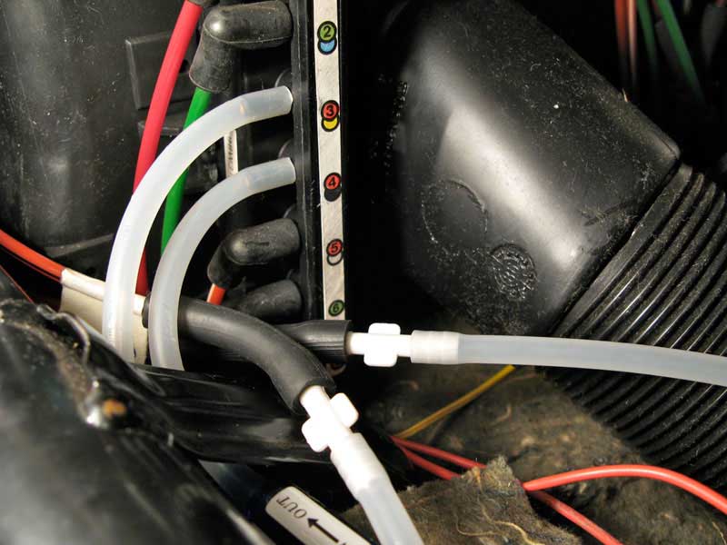
14) On the front of Y7 are numbers 1-7 corresponding to each valve. Number 3 goes to the footwell pod, number 4 goes to the center pod.
Disconnect them, making a note of which is which (you might want to label these if you want to undo everything).
15) Using the photo, cut your hose pieces and put everything together to match mine.
It's very important to install the check valves.
At any given time, one of valves #3 or #4 on Y7 will be open to the air via the open ports on the back of Y7.
The check valves will prevent Y7 from sucking a vacuum through one of our new hoses connected to #3 or #4 and getting unlimited fresh air from the open port on the back of Y7 for the opposite valve.
That would prevent the vacuum suction from getting to the pods.
It's also important to leave the top valve on our new vacuum relays open to allow air to flow through to the vacuum pod when we want to turn that pod off (by energizing the respective vacuum relay).

16) I'm not sure if it matters which side of the vacuum relay you connect ground to, but I just did whatever was done in the car that I took the vacuum relays from. (You can also look in your own car).
So, in that case, connect a ground wire to each vacuum relay using the pin on the same side as the part numbers.
Connect a separate wire to each of the other pins (on the same side as the little diagram), and run these two wires through to the center console compartment where your power wire went earlier (step #11).
17) Tuck the vacuum relays, hoses, and wires down in the space at the bottom of the glove box compartment between the black crossmember and the black air duct.
I tucked all the hoses with the check valves under the bracket holding the crossmember, and left the original hoses going to the vacuum pods above that bracket.
Do whatever works for you, but be careful not to disconnect the center vacuum line from the rubber angle connector that leads into the middle of the air box where the center vent pod lives.
You should be able to see this with the ACC unit pulled out of the way (see picture in step #6).

18) You can test your creation at this point.
The key is to use a setting on the ACC that you know will produce air from either one of the center or footwell vents.
Turn the car on and press one of the non-defrost buttons on the ACC unit (warm the car up if necessary).
None of the three wires you pulled through the dash (one hot and two from the vacuum relays) should be connected to one another - this way air should be coming out of both of the center and footwell vents.
If you connect one of the relay wires to hot, that vacuum relay's solenoid should energize and turn off flow to it's respective pod - stopping the flow of air to that vent.
Try it with the other wire to test the other vacuum relay.
Now we're on to the switch.
This next section will depend greatly on the type of switch you are going to use.
If you're not using the same type of switch that I am, then you're on your own.
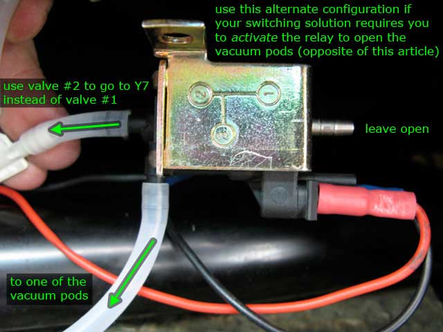
The only thing you need to know is that with the way the vacuum relays are configured with the hoses, powering the relay will stop the vacuum flow to the pod, closing the flap.
If your switching solution requires that you do the opposite (energize the vacuum relay in order to send vacuum to the pod, opening the flap), then you just need to move the hoses from the bottom (valve #1) of the vacuum relays to the top (valve #2).
Leave the hoses connected to the right angle valves (#3). This document, page 8, helps describe the vacuum relays (they're called vacuum switchover valves).
You can install the switch as is, but the way we're using it, the illumination LEDs do not work when the switch in is the "up" position.
So we need to install a new ground pin to separate the illumination circuit from the switch circuit.
Steps #19-26 are optional, but I recommend them.
If you want to skip them, then I would not recommend connecting an illumination wire to this particular switch.
(OPTIONAL - but recommended)
19) Pry off the cover of the junk wiring harness.
You should be able to easily remove any one of the sockets, keeping the wire attached.
20) Pry off the cover and base of the junk switch you have.
You need to remove one of the pins. Find one that can easily be disconnected from the inner wiring, unsoldering where necessary.
Usually the pin connected to a resistor or an LED is easiest.
Others may be pressed into metal plates or washers.
In either case, the pin is press fitted into the plastic and can be very hard to pull out.
I found that pressing the hot soldering iron against the exposed portion of the pin will heat it up enough to melt the plastic around it just enough to ease its removal.
You could also cut the plastic around it.
Once the pin is out, set it aside with the socket from the last step.
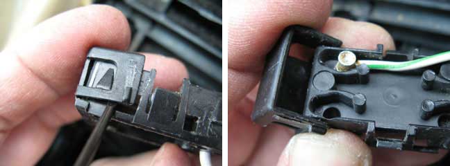
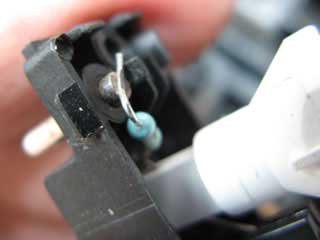
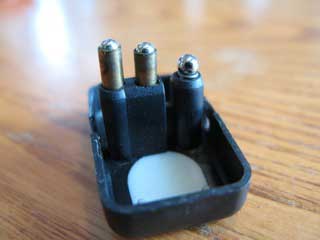
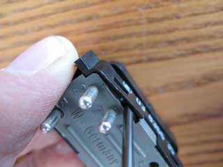
Here's the switch I used for the pin:
Pry off the bottom:
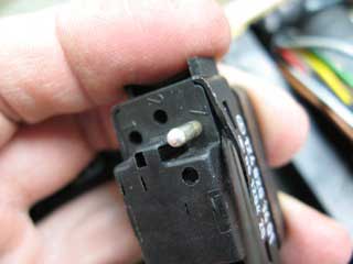
This is an easy pin to remove. Just unsolder the resistor and heat the pin to melt the plastic surrounding it.
Slide it out.
21) Now pry of the one side of the cover of the wiring harness you got with your new switch.
You'll need to pry off the side with the numbers 1, 3, and 4.
Add the socket you removed in the step #19 to spot #4.
Close the clip.
22) Take the new switch and remove the top cover, keeping in mind how it goes back on.
Look inside and take a picture or note how it all fits together.
Remove the ball bearing and any loose springs, set them with the top.
(I didn't have any photos of the switch before I altered it, so I used a newer version of the switch with the same insides for these next three photos.)
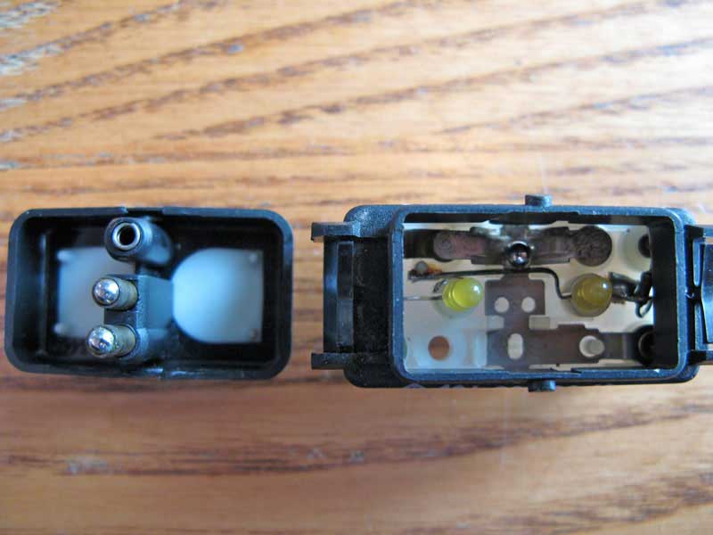
Watch out for these ball bearings, shafts, and springs.
They will fall out.
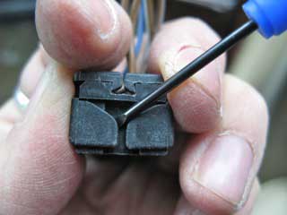
23) Flip the switch over and remove the bottom (gray plastic) by prying with a very small screwdriver to lift the plastic case free from the four little tabs.
Be careful not to break the plastic.
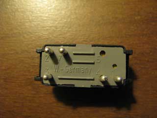
24) Find the hole labeled #4 in the bottom of the switch.
Take the pin you removed in step #20 and press it firmly into that empty hole from the top.
Be sure it's in there very tight.
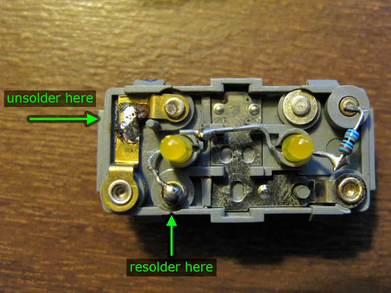
25) Notice how one lead of the LEDs is soldered to the metal strip connecting pin 1 to 5.
Carefully unsolder this lead. Use some small needle-nose pliers to bend the lead over to your new pin in hole #4.
Solder it to that pin.
26) Put the switch back together.
Make sure it fits into your wiring harness.
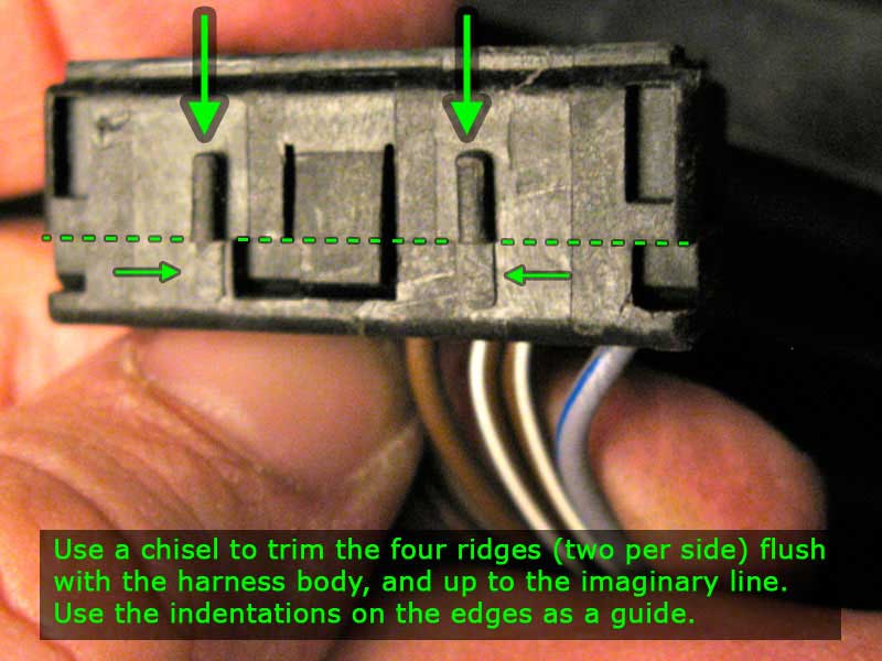
27) If you are installing the switch into the lower console in place of the fader switch, you will probably need to shave off a small amount of plastic from the four little ridges on the sides in order for the switch to rest low enough in the empty space left by the fader switch.
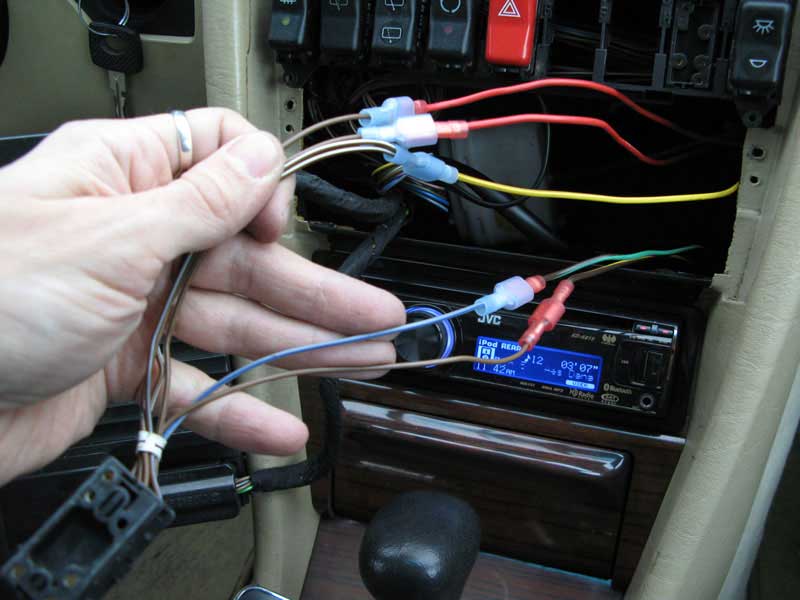
28) Feed the wires of your wiring harness through the appropriate opening above the ACC unit (or in the fader spot).
Connect the wire like this:
- pin 2 (gray/blue): power for the illumination - find one to tap into, usually a gray/blue wire, I used one from my old fader switch
- pin 4 (what ever color you got with your socket): ground for illumination - again, I used one from my old fader switch
- pin 3 (two brown/white wires together): hot from the glove box light (or other source that's only on when the key is in the "accy." "run" or "on" position) - this powers our vacuum relays
- pin 1 (brown): connect to the vacuum relay for the footwell pod
- pin 7 (brown/blue): connect to the vacuum relay for the center pod
29) Test the switch.
- When the switch is in the upper position, it energizes the footwell vacuum relay and no air comes out of the footwell vents.
- When the switch is in the center position, neither of the vacuum relays are energized and air comes out of both center and footwell vents.
- When the switch is in the lower position, it energizes the center vacuum relay and no air comes out of the center dash vents.
If the upper and lower switch positions do the opposite of what is described above, just swap the wires to pins 1 and 7.
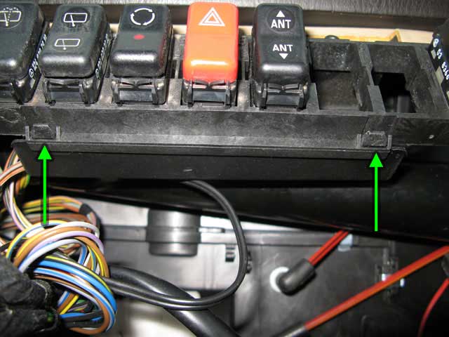
30a) Remove the plastic thing covering all the wires to the switch harnesses behind the switches.
Press in the four tabs (two above and two below the switches).
It's a tight fit behind there, but it's flexible so just work it out to the right and down.
Insert your new switch wiring harness (without your switch plugged into it) in through the back of the empty spot above the ACC unit.
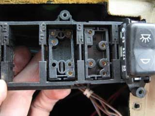
If you need to move or rearrange any switches, the harnesses will come free if you apply a little pressure with a screwdriver on each side of the harness.
-OR-
30b) If you are putting your switch into the fader switch spot, first rest the switch into the empty spot and make sure it rests level with the passenger window switch.
Cut extra off the plastic ridges (see step #27) if necessary.
Put the switch into the harness and clip it up onto the back of the wooden console panel (just like the fader switch did).
I do not have any picture of this.
31) Tuck all wires out of the way and put the ACC unit back in place.
32) Install your new console panel with the opening for your new switch (or if you used the fader spot, screw the lower console panel back in place).
33) Put the glove box door back on, followed by the glove box liner (don't forget to pull the wires for the light out through the opening in the liner), then the latch at the top of the liner.
34) Enjoy!
ADDENDUM
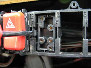
As soon as I finished this write-up, I started playing with that switch that I gave up on... the rear window screen switch (124-821-04-51) with the icons that look sort of like upper and lower vents.
It dawned on me that it wouldn't be too hard to make the rocker stay in the upper and lower positions. I took some cues from the way the other switches do it.
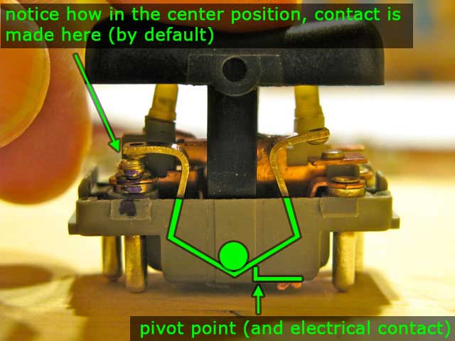
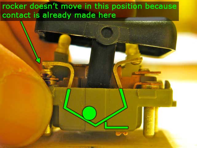
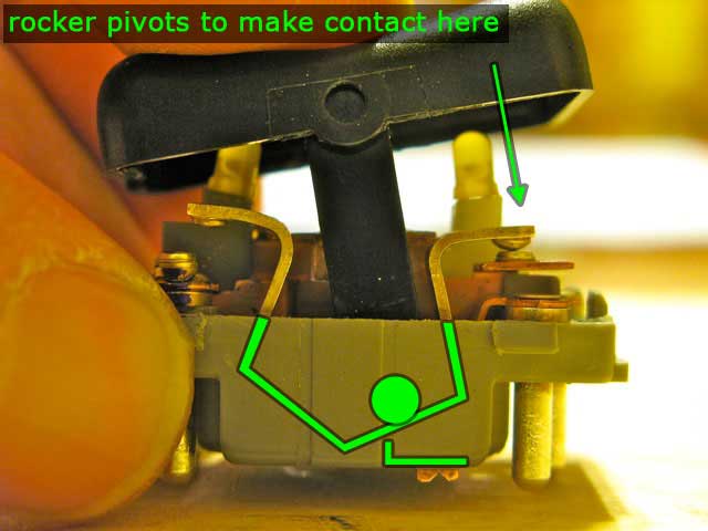
Basically, like many other switches, this switch has a ball bearing in it that is under pressure from a spring. The ball rests in the low point of an internal vee shaped brass rocker. When the outer plastic rocker is actuated, the ball is pushed up one of the sides of the brass rocker, compressing the spring and increasing the pressure on the ball. When you release the switch, the pressure from the spring makes the ball return to the low point or center point in the switch, returning the rocker to it's central position. When the switch pushes the ball up the side of the rocker, that rocker pivots just enough for the tops of it to make contact with a metal post, closing a circuit.
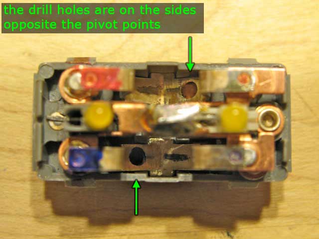
The way to make the switch stay in one of the actuated positions is to keep the ball from sliding back down to the bottom of the vee. This is easily done by drilling a small hole in the side of the rocker for the ball to rest in. A 5/32" hole is just big enough to overcome the spring's pressure, and not too big to make it hard to get the ball out.
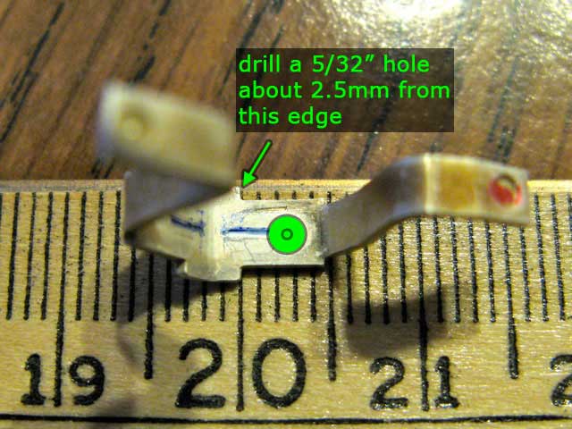
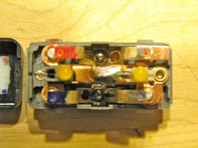
The inside of the switch actually has two of these vee shaped rockers and two ball bearings.
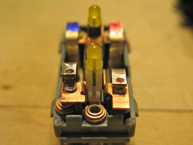
There are two separate small metal plates, one under each rocker with an upward bend that makes contact with each rocker. These upward bends are the pivot points for the rockers. On one side of the switch this contact is just to the right of center of one of the rockers, and on the other side of the switch this contact is made just to the left of center of the other rocker. The fact that these contacts are made off center makes the two rockers tilt in opposite directions.
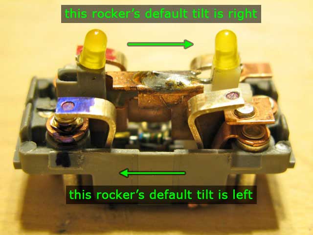
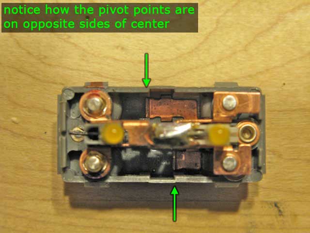
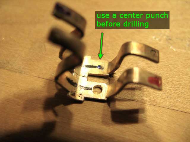
I bring up this detail because when we drill holes in the arms of the rockers, the hole has to be above these pivot points. Otherwise there will be too much play in the switch when the ball bearing is "resting" in the hole - resulting in inconsistent contact between the rocker and the metal post. In fact, it's actually best to only drill one hole in each rocker, and locate that hole on the side of the rocker that doesn't contact the pivot point. Since the pivot points for the two rockers are on opposite sides, there will be only one hole to lock the ball bearings in place in each of the two switch positions (up and down). While one ball is locked in place, it will be the other ball on the other side of the switch that is pushing the brass rocker over the pivot point - making contact with the metal post.
This switch has to be wired differently than the interior dome lamp switch (124-821-02-51) I used in the write-up. Here's a new schematic:
Much Better!
-Zeb
Discuss this DIY here.
-zebellis
CategoryDiy