It's difficult to show how the tool is used in the car because there are no good photo angles. Heck, there are no good viewing angles either - I had my eyes on one end of the bushing with one hand working blindly on the other end. The best overall view is from directly below but who wants these chunky tools falling on their face? It was easy enough to work chest-to-rotor, as it were. Here's my attempt at describing the usage of Dave's tool set:
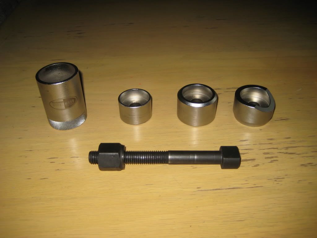
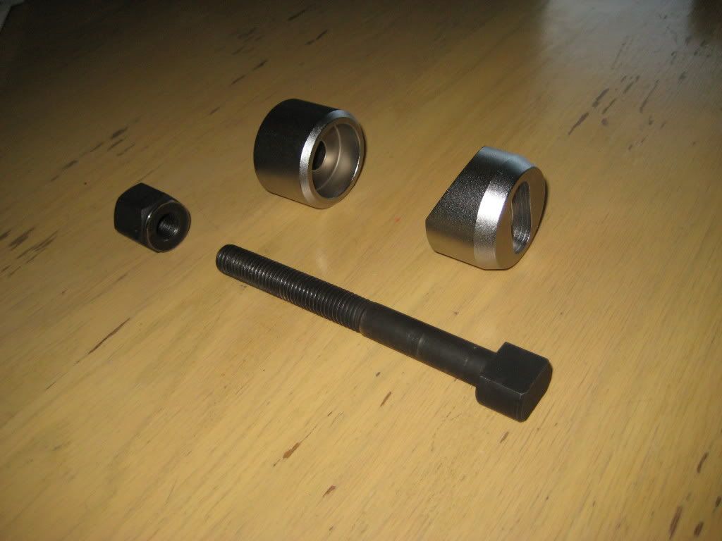
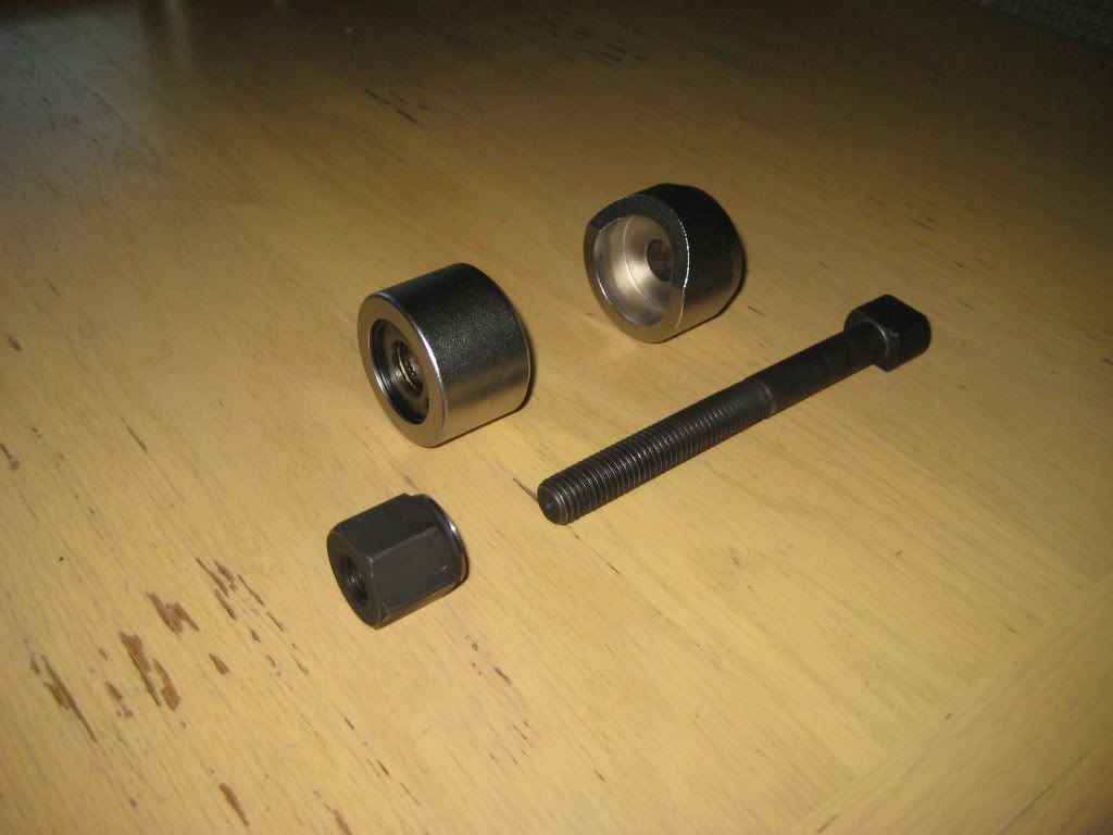
This is the tool set out of the case. I'll switch terminology from earlier posts to align with how each part is used in the job. Silver pieces from left to right are: removal receiver, removal drift, installation drift, installation receiver; dark piece is the screw with nut attached -
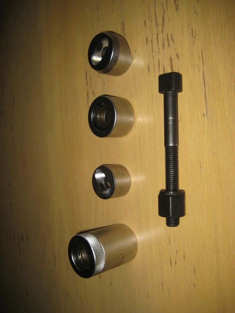
The silver pieces are in the same order but inverted. You can just see that the removal receiver and installation drift have bearings against which the tapered end of the nut pushes, while the the removal drift and installation receiver have slots into which the oblong head of the screw fits -
Removal mode viewed from the front. Note that the head of the screw always points to the front of the car and the nut always goes on from the rear of the car. The old bushing is removed by pushing it rearward and the new bushing is installed by pushing it forward. You'll have to use your imagination to envision the old bushing set in the hub carrier with the removal receiver to the rear and the removal drift to the front. The removal drift fits snugly over the exposed end of the old bushing and its overall diameter is smaller than the major diameter of the old bushing so you don't have to worry about centering the removal drift as you turn the nut. The removal drift will go right through the hub carrier as it pushes out the old bushing. At some point while turning the nut there will be no resistance and the tool set and bushing will fall off the hub carrier -
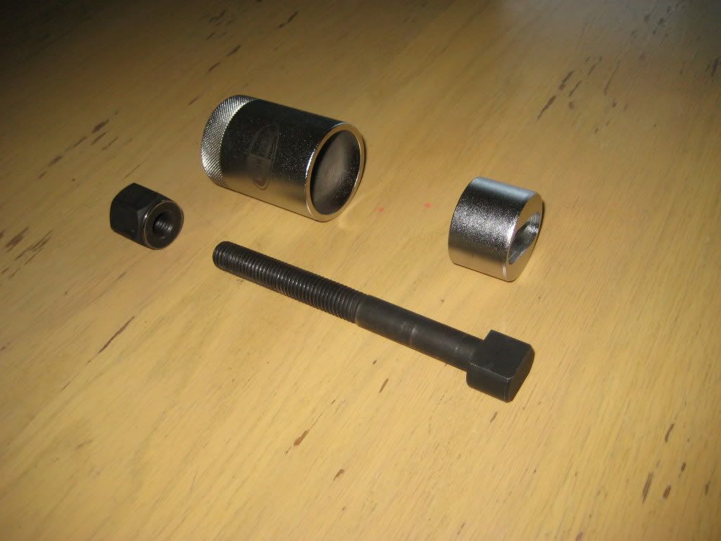
Removal mode viewed from the rear. The only difficulty with using this tool is the removal receiver can be positioned such that the outer annulus of the bushings hits the rim of the removal receiver. This results in the tool binding. I used moderate force on an 8" socket driver. There was uniform resistance until the bushing contacted the removal receiver. At that point I switched to an 18" breaker bar and applied about as much force as would release a wheel lug bolt. No joy. I undid the tool, studied the situation and came to the conclusion that the bushing contacted the removal receiver. In the second setup, I used the circumference of the hub carrier around the bushing hole as a guide to visually center removal receiver. Joy! I sensed the slightest bit of magnetic attraction between the nut and the removal receiver. It doesn't really matter since the tapered end of the nut is almost a precision fit against the bearing in the removal receiver -
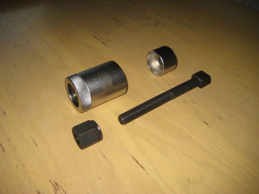
Installation mode viewed from the front. The slice removed from the mating end of the of the installation receiver allows the installation receiver to fit squarely against the hub carrier bushing hole. There is a section of the hub carrier that doesn't allow the installation receiver to have full circumference contact with the hub carrier. The exposed end of the bushing, either exposed end since the bushing is symmetrical (Dave, please confirm!), fits snugly in the installation drift. I found it easiest to set the installation receiver in place, then set the screw in place, then set the installation drift with new bushing onto the screw. This sets up alignment between the bushing and the hub carrier hole close enough that no further tweaking is necessary. No more force is needed to turn the nut to install the new bushing than is used to remove the old bushing. At the first hint of resistance, remove the tool to check progress. I found this tool set the bushing outer annulus flush with the hub carrier hole rear surface and extending something like 2mm from the forward surface. I didn't note how the old bushing was installed so I used the tool in removal mode to push the bushing back about 1mm so the there was as much exposed annulus on both surfaces of the hub carrier -
Installation mode viewed from the rear. The slice missing from the installation receiver actually goes towards the bottom when in use. Gravity caused the installation receiver to sit with the slice towards the top in these photos -
Sixto
87 300D