Quote:
Originally Posted by boise outlaw

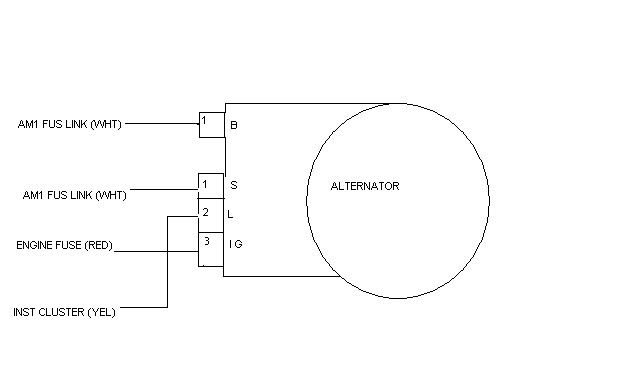
here is the diagram for the stock alternator for a 22r motor. I would be splicing the white/blue with the yellow instrument cluster wire. I would not be using any of the others as they are on the drivers side fender well and it would be much easier to run the red/white wires directly to the battery. So it is my understanding that with "key on" but not running the battery lamp would be on, but once running the blue/white has a positive charge and lamp will be off?
Also just out of curiosity whats the purpose of 2 white/red charging wires? do they produce different fields of AC current?
|
Re: diagrams
The chassis diagram would be needed to see how the indicator light is wired. You can check for 12V+ at the yellow wire with KeyOn.
Your understanding of the light operation is correct.
Two red/white wires (B+) are used to provide extra current capacity, rather that using one larger, and less flexible wire.