

|
|
|
|
|
|
#1
 06-01-2008, 11:54 PM
|
|||
|
|||
|
1993 2.6 190E Coolant Temperature Sensor Wiring
i have some questions about the coolant temperature sensor on the m103 2.6 in 1993.
First, ive noticed on ******** that there are 3 different coolant temperature sensors? This is for CIS/EZL signals ?: http://www.***************/secure/PartImages/0085423217.jpg aux fan signal ?: http://www.***************/secure/PartImages/0085424517.jpg instrument cluster signal ?: http://www.***************/secure/PartImages/0055421017.jpg is that what those 3 sensors are for? next question: how do I know that i plugged the 4 prong connector from the wiring harness correctly into the sensor at the back of the engine? there is no indication on which way it connects, ive just been plugging it in based on the orientation i remember from unplugging it in the first place. not sure how to verify that is the correct way it goes. next question: how does this 4 prong sensor work? it looks like one of the prongs is ground, the other gives off a resistance of ranging from ~2000 ohm when cold and ~300 when engine is hot. the resistance based signal seems to be connected to the EZL on pin 1 based on a continuity test. the other two signals I am not sure about, but one of them is connected to pin 21 on the ECU wiring harness (i suppose this is for controlling a/f mixtures), but how is that signal being generated? It does not give off any resistance, nor could I measure a voltage when tested against ground. should all 3 prongs be giving off resistance values and the one I have is broken? other question: how does the instrument cluster water temp sensor work? is it based off a voltage or a resistance? i could not measure a resistance when tested against ground. sorry for so many questions! 
|
|
#2
06-02-2008, 12:42 AM
|
|||
|
|||
|
while searching benzworld, i found this interesting picture:
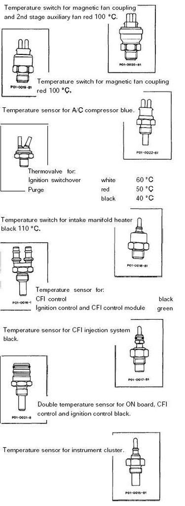 i think the 4 prong sensor is the second to last one I am looking at: "Double temperature sensor for ON board, CFI control and ignition control black". what does it mean, sensor for ON board? That could be describing the other prong I cannot figure out.
|
|
#3
06-02-2008, 01:08 AM
|
|||
|
|||
|
more digging and more information
 this looks like the 4 prong connector. this kind of matches up with what I found earlier. but now, what does ECT (engine coolant temperature?), ICM (ignition control module?), ECM (engine control module?) mean? This is what I found when I was metering out the wires: #1 connected to EZL, gave a resistance reading when tested against ground #2 ??? couldnt find #3 ground #4 connected to pin 21 on the ECU, could not interpret the signal if ECM stands for engine control module signals, then that means prong #2 and #4 both connect to the ECU, and maybe it gives off a voltage or something to read the signal from the sensor?
|
|
#4
06-02-2008, 09:47 AM
|
|||
|
|||
|
The gauge sensor is a thermistor and it is the single pin one.
110 ohms-60 C 67 ohms -80 C 38 ohms-100 C The 2 wire blu is a thermistor and it is temp input to the ACC panel [ Aux High Fan uses this input]. The orientation of the sensor at the back of the head makes no difference b/c it is 2 thermistors in one case and they are wired Diagonally across the pins and are of the same value, so it can be plugged in any way and be correct.
__________________
A Dalton Last edited by Arthur Dalton; 06-02-2008 at 09:53 AM.
|
|
#5
06-02-2008, 09:58 AM
|
|||
|
|||
|
so if i cannot get resistance on the pins when tested against ground, that means my sensor is broken? my cluster gauge works perfectly fine, however, i couldnt get a resistance from the gauge sensor. am i doing the test incorrectly?
|
|
#6
06-02-2008, 10:07 AM
|
|||
|
|||
|
Quote:
There has to be an R value from the pin to ground or the gauge would not be working. The R will be variable with the coolant temp [ Negative Coefficent Thermistor]..meaning R decreases as temp increases Zero your meter and then try it..I gave you the Ohm values. The gauge should NOT work when you unplug the sensor....... http://catalog.worldpac.com/mercedesshop/sophio/wizard.jsp?partner=mercedesshop&clientid=catalog.mercedesshop&baseurl=http://catalog.peachparts.com/&cookieid=2AO123CS42DU0M0ZSB&year=1993&make=MB&model=190-E-005&category=P&part=Water+Temperature+Sender
__________________
A Dalton Last edited by Arthur Dalton; 06-02-2008 at 10:18 AM.
|
|
#7
06-02-2008, 12:28 PM
|
||||
|
||||
|
Quote:
The blue sensor shows about 310 ohms @ 100C for example as measured across both pins.
|
|
#8
06-02-2008, 12:30 PM
|
|||
|
|||
|
Quote:
__________________
A Dalton
|
|
#9
06-02-2008, 01:00 PM
|
|||
|
|||
|
alright, so for the gauge sensor, i measure it against ground.
for the 4 pin connector, im supposed to measure it across the pins. well that explains why only one pin was giving a resistance when I was testing it against ground, since one of the pins is ground. I'll give this another try later.
|
 |
| Bookmarks |
|
|


 Linear Mode


