Head Gasket Replacement
on the M104 Engine
by Steve Brotherton
First Published in: ImportCar
With most engines we currently see, a head gasket repair is usually preceded by a severe cooling system failure. And with most modern motors, you're usually better off just installing a used one when they've been heated to the point of head gasket failure. The modern thin-walled castings just leave too many risks for doing these infrequent repairs.
The Mercedes-Benz 104 inline six is the final extension of an inline motor the carmaker had been building since at least the 1960s. Some of these motors were almost bulletproof, but they all seemed to have at least one shortcoming.
In recent history, the 104's direct cousin, the single-cam 103 motor, had problems with valve guide seals and maybe even the guides themselves. But not the 104 motor. The bottom end is probably bulletproof, as I have never seen one that was worn out (although I should note that they have been out only since 1990).
The 104 motor, even with all of its mechanical excellence, does have this one nasty little aggravation: With great regularity, it acquires a significant oil leak. This leak can occur at the front of the cylinder head for at least four different reasons. In this article, I'll examine these problem areas and also share how to correct them.
PROBLEM LEAKS
The most common leak occurs where the upper timing cover resilient gasket butts into the leading edge of the cylinder head or head gasket. If the motor were like most being built, it would have a cam belt and the area in question wouldn't even exist. The cylinder head would sit on the gasket on the block, and compression or maybe some coolant would be the only possible leaks to the front. Mercedes puts a dual roller chain on this piece of equipment and, of course, it rides in the oil-scattered cavity in front of the head-block combination.
The front of the motor is housed in the leading portion of the pan and the lower and upper cast-aluminum covers. The covers are finely machined and are sealed to the front of the motor without gaskets. Between the upper and lower case is the resilient seal. It is a U-shaped, fairly spongy, 4mm-thick gasket.
The job of sealing the two covers is efficiently accomplished with this seal when done properly. The problem arises in sealing the ends of the "U" against the rear surface. That surface is the area where the head, head gasket and block come together. If it were just against a smooth surface, it would be easy. Instead, it's located in this rough area of convergence. Based on the way that Mercedes has reinforced the newer head gaskets right behind this area (see Photo 1).
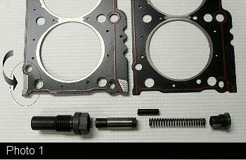
It's my diagnosis that part of the long-range problem is that the head gasket recedes under the head after a period of time. Over time, the resilience of that spongy gasket can't keep up with the receding gasket and a leak is formed.
Diagnostic information on this subject proposes that to locate the leak, you should first reseal the upper cam housing. If that doesn't solve the leak, it's recommended that you should replace the head gasket and then reseal the upper cover. I can tell you from experience that a customer won't understand that logic: The first time we used that technique to save a good customer money, it caused us to learn the rest of the story out of R&D funds. As a result, in the future, we probably will do a head gasket on every virgin motor we come across that has a good leak.
Most of this discourse is designed to put this repair into a proper perspective. That is, it's just a head gasket so don't go rebuilding the motor over it. The valve guides don't wear out in this engine, and the chain rarely, if ever, has problems. Just replace the gasket and fix the leak.
Because Mercedes-Benz engines fit together so well, there's really nothing special about this job. It's hard to put them together wrong. And I won't be telling you every bolt to remove, since this job should be self-explanatory at this level. I will try to point out our techniques and the various problem points.
JOB RISKS
There are a number of risks to this job that are not technical in nature. The first, and maybe most important, deals with the original diagnostics and the sale of the job. Unlike the motor pictured during the disassembly, most of the ones being fixed are likely to be 1993-'95 HFM-injected models. These years have a significant problem with the wiring harness insulation falling apart (see Photo 2).
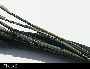
The act of doing this work will ruin a harness that is falling apart. It's very expensive, and something you won't need at the end of the job. The harness problems occur on the engine harness on the engine, the engine harness on the body and the harness from the throttle actuator. Be sure to check the state of these harnesses before selling this job on 1993-'95 models.
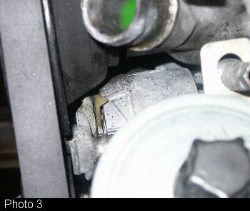
Another job risk on M-B models through 1995 involves the belt tensioner. A close evaluation or warning of risk involving the serpentine belt tensioner and water pump should be involved with estimating the job. The belt tensioner is rather pricey and always seems to fail upon reassembly. The belt tensioner is a rubber hub design, sort of like a big suspension bushing. Tension is applied by the mechanical adjuster to the inner hub. The rubber is stretched as the roller attached to the outer hub is pulled against the belt. A proper rubber hub will transmit the proper tension when the arrow is pulled to the mark as seen in Photo 3.
DISASSEMBLY
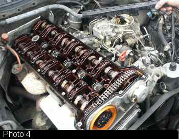
The first point of disassembly is to remove the head, intake and exhaust in one unit. So one of the first things we do is to remove the wiring harness from the intake (see Photo 4).
The disassembly pictures are from an early motor with an aluminum manifold and CIS-E fuel system. Most of the cars we've done have been the HFM fuel systems which have a two-part plastic/aluminum intake manifold. The two halves are connected by two large rubber hoses (see Photo 5).
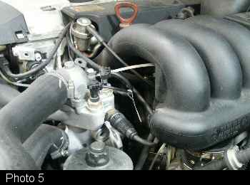
We remove the head with the top/plastic manifold, separating it at those two large hoses.
The upper timing cover is easily removed. It is a good idea to make yourself familiar with the timing marks and their orientation at this point. As you'll see in Photo 6,
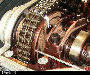
we've made a mark across the chain and gear. This is a cross-check for use in final assembly of the intake cam timing adjuster. The proper location of the cam is indicated by a 4mm drift ({any 4mm rod can be used} see the drill in photo 6). In the proper position, the drift fits into the hole in the flange and sits on the parting surface of the head. The same arrangement exists on the exhaust side.
This is all just paint-by-numbers, except for the orientation of the intake cam timer. The fact that you have the intake cam doweled correctly, the exhaust cam doweled correctly and the crank on number one is not enough. You should have all of this, and the intake cam must be in the retard position with respect to TDC with the chain tight in the correct direction.
This activity of the cam timer is the most common first-time mistake. Unfortunately, the engine runs pretty decent in the right or wrong condition. If the timing is done wrong by setting the timer the wrong way, it will set various fault codes for cam timing depending on the systems used. We have had this happen at least twice in our shop, and it's no fun to have to go back in to fix it. Thankfully though, it hasn't bent any valves.
GEAR ASSEMBLY
I've described how to get the sequence of assembling the gear on the intake cam right a number of times over the phone. The easiest way for me to explain it here goes like this: Forget the chain for the moment and place both cams on their doweled marks. Take the intake gear and turn it clockwise, looking straight at it from the front (don't move the cam).
In this position, the cams are on the marks, the crank should have stayed there from first disassembly and, most importantly, the cam, while in its mark, is retarded in the adjuster. If the chain were in pieces, you could just drape it over and pin it and you'd be set. It can't be assembled in this way, since we don't break the chain in the operation.
This example is conceptual to describe the effective positioning of all parts. During actual assembly, you must get the chain on the gear, have it pulled tight on the driver's side and be sure that the cam is retarded to match the concept above.
After becoming acquainted with the cam timing arrangement, remove the exhaust gear. Probably one of the toughest issues can be the removal of the pin from the driver's side guide rail (see Photo 7).
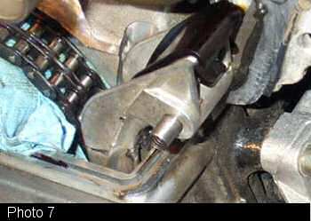
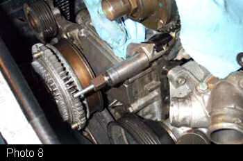
This pin is often difficult and must be removed to get the head off. We use a small slide hammer of our own manufacture. The center of the pin is threaded, and it can be pulled with a bolt and various cylindrical spacers such as the socket in Photo 8.
The chain should be hung with a piece of shop wire, and the tensioner should be removed.
ENGINE REMOVAL
So with everything disconnected, we often use the engine hoist to get it all out (see Photo 9).

Two or three big, young techs can do it without the use of a hoist, but it's a big challenge. The nice thing about the engine hoist is that when you're a couple of inches up and discover that you forgot to disconnect the EGR pipe, you don't have to find help again when it's disconnected.
Speaking of the EGR, the HFM system, with its big throttle actuator handling idle control, does a real good job of adapting to a lot of problems including vacuum leaks and loose EGR pipes. They willprobably set codes, but don't forget to tighten the EGR (one of the failures that became an unfunded, new diagnostic repair in our shop).
Once it's all cleaned up, just put it back together. With all of this work, I tend to buy only top-of-the-line materials.
PROPER CHAIN TENSIONER HANDLING
The most important technique after getting the timing correct is to properly handle the chain tensioner. It should be removed during disassembly. It is a ratcheting-type tensioner, and once the chain isn't opposing it, it will extend. It won't go back and can ruin a real good week when it does its damage by overtightening the chain. The tensioner must be disassembled before installation (again refer to Photo 1).
Installation involves putting the body of the tensioner back first, with the chain and cams timed. Then install the plunger, spring/spacer and end cap. The act of installing the spring will push the plunger into the chain tensioning rail. If it doesn't, it is because the clip/ring isn't starting in the ratcheting bore. In this case, tap the piston/plunger with a punch to start it in the bore. A distinct tap will do it, whereas the constant pressure of the spring may be more than your hand can handle.
SEALING THE FRONT COVER
One of the last steps is sealing the front cover that caused the whole problem. Unfortunately, the front cover has to come onto the pin on the driver's side horizontally and, in that position, the gasket won't fit. As a result, the whole thing has to be assembled very carefully. (It's a problem that's similar to the seal on the top of Volvo four-cylinder water pumps.) Care must be taken as the cover is pushed down and back, not to roll the seal out of the indentation in the lower cover.
The process of sealing also has been covered in updated information from Mercedes. There are two recommended sealants: The first,M-B p/n 002 989 47 20 10, is used sparingly on the vertical metal-to-metal surfaces. At the point of convergence between the head, head gasket and the cover seal (see Photo 10 with the head removed),
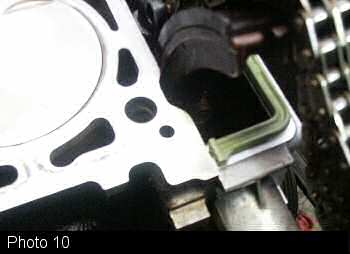
a dab of M-B p/n 001 989 61 20 10 should be placed before assembly. There are other similar sealants that make a sticky flexible seal, but the M-B variety works well. No sealant should be used on the "U" seal (except where the dab sits at the ends of the "U").
ALMOST FINISHED
So, the rest is a piece of cake. The remaining pitfalls are usually a "check engine" light after a five-mile drive. It seems that quite often the vacuum lines to the switchover valve at the front of the motor get switched (see Photo 11).
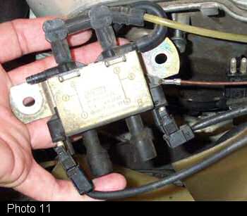
These are for control of the EGR and Secondary Air Injection, and reversal is first noticed with an EGR code. Speaking of the EGR, as mentioned earlier, we usually disconnect the EGR pipe at the valve and leave it when the head is removed. The other end of the pipe goes into the lower manifold, and one of the most common EGR flow codes is caused by a build-up of dried, burned, oily PCV vapors that cake onto the hot pipe. While the head is off, the pipe flange is very accessible. I would recommend pulling the steel pipe from the manifold and cleaning this port.
You're just about done now. The last typical problem caused by the movement during the repair process involves the plug connector, M-B # 000 159 36 42, mounted to the three coils used in the 1993-'96 HFM models. They are inexpensive, and I replace them every time I replace the plugs since they routinely cause misfires that are very hard to identify.
The final aspect of the job should involve an extended test drive and a scan verification that all codes are gone and the throttle is adapted. Throttle linkages should be lubed and proper free-play adjustments made. A tight throttle cable can cause a lot of problems with traction control and can cause a "limp home" rpm limitation.
- Steve Brotherton
Webmaster note - Be sure to visit THIS THREAD for additional notes and comments regarding M104 Head Gasket replacement.
CategoryDiy