

|
|
|
|
|
|
|
|
#1
 03-06-2006, 09:50 PM
|
|||
|
|||
|
My head gasket replacement notes (long) - M104 '95 E320
For MB board: Ok, these are my notes on the head gasket replacement for my 98k ’95 E320 M104 engine. Now before you pull the head or any of the other components described in my writeup, I recommend you print out the head gasket replacement, upper timing cover removal, timing chain tensioner removal and engine timing (lining up the cam gears with the crank on TDC) from the MB repair CD. I also recommend you print Steve Brotherton’s excellent writeup. And above all, go slowly and use common sense. I didn’t always do this, and made a couple mistakes that could’ve sunk me. Oh yes, – and remove the negative battery cable from the battery.
http://www.peachparts.com/Wikka/M104HeadGasket You can pull the head one of three ways. 1. Head only: unbolt the intake and exhaust manifolds from the head 2. Head + exhaust manifolds: (M104 has two manifolds – three cylinders each) - unbolt the intake manifold from the H-pipes, and the intake manifold from the head 3. Head + exhaust manifolds + intake (unbolt the exhaust manifolds from the H-pipes, and the remove the fuel lines, coolant line, vacuum lines, electrical connext and losen the hose clamps attaching the upper portion of the intake manifold. As I was primarily on my own (tough job – requires a strong back or two to hoist it out the engine compartment), I opted for method #2 – left the exhaust manifolds bolted to the head. If could do again, I would rent/borrow an engine hoist/chain, and pull the manifolds while still on the head. My neighbor helped me pull the head/exhaust manifolds out of the car. I climbed in the engine compartment and installed it myself without help. A few thoughts: Front cover: I’m really a pro at getting this off and on quickly. It’s VERY simple, and you don’t need to remove the serpentine belt. I always do in this order. First, loosen the fan shroud. Then, drain the coolant at the crossover pipe connection just above the AIR pump. Then, pull the switchover valve (two 13mm bolts), and move the electrical connections to the side. Also the connection to the AIR pump. I then remove the black engine lift hook (two long hex bolts) right next to the switchover valve (these are the items hidden behind the black cover (front of the engine), and pull the engine lift hook. You can then remove the large coolant hose in the front. Two hose clamps. From there, it’s very simple to remove the coolant crossover pipe – single hex bolt holding to the block, and the small bolt holding it to the thermostat housing. With the pipe out of the way, pulling the fan is simple. I use a piece of angled steel rod – bent for this need – I think it’s ¼” that I can slide in to the groove behind the cooling fan pulley. With this in place (the rod), with the other hand, put an allen wrench into the hex bolt on the cooling fan. Turn clockwise until the rod “locks” down the fan pulley. Then loosen the cooling fan pulley by loosening the bolt counter clockwise. With the fan out of the way, I would suggest removing the valve cover. I won’t explain that process – it’s an easy task. With the valve cover off, you can pull the timing cover. There are six bolts that hold it in place – you won’t be able to remove the lower bolt on the passenger side – just unthread it and leave it loose. Also, remove the bolt holding the belt tensioner “shock” absorber. The upper timing cover will now come off. Careful – I use a flathead screwdriver on the passenger side first, then on the drivers side. There are a couple pry points. Don’t try and pry anywhere else. A rubber mallet may also do the trick. Once off, I remove the “pin” attaching the timing chain rail on the driver’s side. I use a long bolt / washer and a socket. Tighten down the bolt into the threaded pin, and as it gets tight, I turn clockwise with a ratchet on the bolt, and with the other hand, pulling outward toward me with the socket. This will ease out the pin. I recommend putting a clean rag between where the timing chain drops/hangs nto the block. You don’t want to drop any nuts/bolts/tools/dirt down here! Intake manifold: removing the intake manifold (first time attempt) was a major pain. Especially the last/bottom bolt against the firewall. There was a bend/tab on the end of the fuel rail which totally obstructed access to the bottom bolt. I recommend if you remove the intake (or, if you’re comtemplating replacing the water pump), you get a few variations of 6/7mm (can’t remember the size – think it’s 7mm) hex sockets, allen wrenches and extensions – stubby hex sockets ¼” ratchet “wobble/flex” extensions are key. Embarrassed to admit I had to get a sawzall out and carefully remove this tab (attached a small wiring harness). There are two large vacuum lines that attach to the bottom of the intake manifold (next to the third cylinder intake port) – one hose goes to what I think it the throttle body, the other, to I believe the power steering pump area. My hoses were hard as a rock, and when I tried to remove them from the intake, I **broke** the two vacuum outlets/ports on the bottom of the intake. The rubber hose, over time, had fused to these ports. So, I had to drill out the two broken connections in the intake and tap them for the two brass fittings I bought at Home Depot. The hose outlet to the front of the intake needed to be approximately 3/8”, the one to the back (to the throttle body), is smaller. I then used Jbweld, after I threaded in the new brass ports, not only to rebuild/seal up broken sections around the ports, but to further seal up things around the brass fittings. Kinda cheesy, but it worked. I do think now that I could’ve removed this broken section from the bottom of the intake (it’s double layered, and seems to be designed to replace), but I was running out of time. You might check with the dealer on this. However, I **strongly** recommend if you pull the intake, you consider cutting these two vacuum hoses in half. And with the intake in hand, or at least bolted to the head, you can properly remove them from the intake. After that, I unscrewed the fuel filer cap and removed the two fuel lines (I think the ends were 17mm). You’ll need to loosen the two top clamps on the large air intake hoses that go from the top portion of the intake manifold to the bottom. Then, only a couple small vacuum lines and one electrical connector in the center of the upper intake. You can also loosen the mounting screw for the oil dipstick, and pull the dipstick up and out of the block. Really sounds like more than there is. Exhaust manifolds: Very simple – just unbolted the two manifolds halves from the header pipes. Four bolts in all. One you get to from the engine compartment, the other three, easily from underneath. The EGR tube is simple to remove. I pulled the ERG unit from the right cylinder head by removing the two nuts on either side, and then the single mounting nut. With the intake/head off, it’s kinda easy to remove the EGR tube for cleaning or replacement (one of the mounting bolts at the throttle body is a bit tough). Mine wasn’t too coked up, but I definitely cleaned it out. The coked end was at the throttle body, where the harshest bends are. Make sure to loosen the transmission fluid dipstick mounting bolt/nut, at the back of the head on the exhaust side. Also, there is a hard liquid line that runs to the center of the head, between? The two exhaust manifolds. I simply unbolted this (single bolt/nut) from the block/head, and I believe I loosened it below the manifold too. IMO, not worth removing all the manifold-to-head bolts. (continued in next post) 
|
|
#2
03-06-2006, 09:51 PM
|
|||
|
|||
|
(continued)
Timing gears: (cam gear). One mistake I made was not turning the engine to TDC before starting this process. So, with a 27mm socket/ratchet, turn the engine over by hand clockwise until you are at TDC. (marked on the crankshaft). To be sure you’re at TDC, look on the back of the timing gears. There are small “doweled” holes that you lay an allen wrench (on the top surface of the head ) and slide into these holes. This is TDC. So, make sure the crank is on TDC before you loosen the chain tensioner. I didn’t do this. Thankfully, Arthur Dalton sent me a pdf of this procedure. My mistake: I marked the chain at both cam gears, and then once on each chain rail. I thought this was enough – or the right way. When I reassembled the engine later, with the new head gasket, I lined up my marks thinking I nailed it. Thankfully, Arthur sent the pdf, which explained the procedure. I then checked my timing with the TDC/allen wrench method in the back of the timing gears, and I was a tooth off. So, off came the tensioner and the cam pulley. And I reset the timing. Thanks, Arthur.
I can’t explain it any better than Steve Brotherton’s article. https://www.continentalimports.com/ser_ic100345.html - an excerpt from the article: “I’ve described how to get the sequence of assembling the gear on the intake cam right a number of times over the phone. The easiest way for me to explain it here goes like this: Forget the chain for the moment and place both cams on their doweled marks. Take the intake gear and turn it clockwise, looking straight at it from the front (don’t move the cam). In this position, the cams are on the marks, the crank should have stayed there from first disassembly and, most importantly, the cam, while in its mark, is retarded in the adjuster. If the chain were in pieces, you could just drape it over and pin it and you’d be set. It can’t be assembled in this way, since we don’t break the chain in the operation. This example is conceptual to describe the effective positioning of all parts. During actual assembly, you must get the chain on the gear, have it pulled tight on the driver’s side and be sure that the cam is retarded to match the concept above. After becoming acquainted with the cam timing arrangement, remove the exhaust gear. Probably one of the toughest issues can be the removal of the pin from the driver’s side guide rail (see Photo 7). This pin is often difficult and must be removed to get the head off. We use a small slide hammer of our own manufacture. The center of the pin is threaded, and it can be pulled with a bolt and various cylindrical spacers such as the socket in Photo 8. The chain should be hung with a piece of shop wire, and the tensioner should be removed.” Once I went through the process, Steve’s explanation made perfect sense. So, make sure the engine is at TDC (not just the crank harmonic balancer), and check the position of the doweled marks on the back of the cam gears. I would next loosen the three bolts holding the cam gear on the exhaust side of the motor. Easier to do this with the chain tensioner in place. Once loosened, you can remove the chain tensioner (27mm). Make sure you see the MB cd manual explanation on this (thanks, Arthur!). Now, the chain will be quite loose on either side, where it falls off the cam gears toward the crank gear. I then removed the three bolts in the exhaust-side cam pulley, and removed the pulley. The chain didn’t really want to move out of the way for me to pull it off both cam gears. So I removed the small positioning collar on the passenger side cam gear (small, single bolt in the center of the cam gear). You’ll notice the “center” of the cam gear moves to the left/right (advance/retard). This is ok. It’s very important, per Steve’s writeup, that the cam is retarded in the adjuster when you put the chain back on. Cylinder head: First, you’ll need to remove the wiring harness, or at least move it out of the way. No need for me to explain the hazards of that here. And original wiring harness (brittle) will never survive what you’re about to do. With the plug wires and all engine sensor/attaching points wiring unplugged, you’ll need to remove the wiring plugs from the fuel injectors. They just squeeze together and pull up and off. The point is, you’ll need the harness out of your way. Ok, there is a specific order to loosening/torquing the head bolts. I recommend you see the MB manual. Your new head gasket set will also have a cheat sheet that repeats this order. Remove the head bolts. You will need a special XZN 12-point socket. You can get a set of these (think the size is 12m) at pep boys, or on ebay. With the timing chain off, and the other items/attaching points previously mentioned, removed, the head should come right off. You’ll get water can other garbage down in the cylinders. Just use clean shop towels or a mitivac pump to suck the water out (and the cylinder head bolt holes – in the block). I used a razor blade gasket scraper and a fine scotchbrite pad to remove the gasket material from the head surface. I also removed the “soft” ridge at the top of my cylinder walls. The walls looked great (98k) – cross hatched, just like from the factory. I also used a fine/long file on the block surface --- to make sure it was totally flat with no gasket buildup. I then blew the cylinders with compressed air, and wiped them down with a clean, lint-free rag soaked in oil. With the engine block ready for the gasket, I then placed the gasket on the head --- make sure you set it down correctly --- and covered the block over with a sheet until I was ready for the head. Regarding the cylinder head, you need to be careful scraping it off, as it’s alumimum. I did use a fine wire brush/drill on the carboned combustion chambers and bottom of the valves. And then blue all the debris out by putting compressed air in the intake/exhaust ports, blowing it out out. Of course, the cylinders with the valves closed, this really didn’t matter. Torquing down the head bolts is nerve wracking. Recheck the torque specs, but I believe that the first stage is 41 foot lbs. And do them in order – turn the radio off, and don’t stop for anything. It’s EASY to forget where you are. I did it once. I waited about 15 minutes between stages. Second stage, I used a ½” ratchet and a breaker bar, and I tightened the new stretch bolts 90 degrees, or ¼ of a full turn. The third stage, I did the same thing. Nerve racking, to say the least. Last edited by 71Rcode; 03-07-2006 at 07:03 AM.
|
|
#3
03-06-2006, 09:52 PM
|
|||
|
|||
|
(continued - page 3 of 3)
Timing chain tensioner: Before you can pull the tensioner, remove the AIR pump. Or at least, pull the top bolt on the AIR pump, loosen the bottom one, and slide it out of the way. Of course, you need to loosen and remove the serpentine belt. I recommend only removing the belt at the the motor and by the AIR pump pulley. It’s very easy to reroute the belt incorrectly and strip out your belt tensioner rod. I’ve done it! Thankfully, not lately
 On the end of the tensioner is a hex “cap”. I think it’s 10mm. Loosen this a couple turns before pulling the tensioner (27mm socket). With the tensioner in hand, you will want to remove the cap, and with a ¼” entension put in the side of the hex cap, push the guts of the tensioner out toward what was the engine side. When it’s time to install the housing and “reload” the tensioner, ***be careful*** you don’t crossthread the tensioner housing like I did. It should almost thread in by hand. So, with the guts out of the tensioner housing, and a new or good condition alumimum O-ring on the housing, thread in the tensioner housing. Don’t tighten down all the way. Then, insert the “plunger” first in the hex/cap side of the housing. With the ¼” or 3/8” extension in the housing after the plunger, push down on the plunger until it seats. You’ll feel it. You’ll need it pushed down in the housing to install the spring-loaded cap. Then, insert the spring, the cylinder that sits in the middle of the spring, and the cap. Be aware there is an alumimum O-ring washer that also fits/seats down inside this hex cap. You might consider replacing this too. I used a ratchet/hex socket or an allen wrench to do this. Kind of tricky, with the spring tension against your hand. With the cap seated/tightened, I then torqured the tensioner housing. It will seat at 59 foot lbs. The cap is much less. Again, make sure you’re not cross threading the housing. I lost two+ quarts of oil on the garage floor and about ½ day because I didn’t realize mine was cross threaded. Thankfully I was able to save it and get it rethreaded. BTW, don’t install the tensioner until you have the head back in place and torqued down, and not until your timing gears are aligned with TDC, and the chain is on properly. With the tensioner in place, and everything aligned correctly, I then tighten/torque down the bolts on the cam pulley. On the end of the tensioner is a hex “cap”. I think it’s 10mm. Loosen this a couple turns before pulling the tensioner (27mm socket). With the tensioner in hand, you will want to remove the cap, and with a ¼” entension put in the side of the hex cap, push the guts of the tensioner out toward what was the engine side. When it’s time to install the housing and “reload” the tensioner, ***be careful*** you don’t crossthread the tensioner housing like I did. It should almost thread in by hand. So, with the guts out of the tensioner housing, and a new or good condition alumimum O-ring on the housing, thread in the tensioner housing. Don’t tighten down all the way. Then, insert the “plunger” first in the hex/cap side of the housing. With the ¼” or 3/8” extension in the housing after the plunger, push down on the plunger until it seats. You’ll feel it. You’ll need it pushed down in the housing to install the spring-loaded cap. Then, insert the spring, the cylinder that sits in the middle of the spring, and the cap. Be aware there is an alumimum O-ring washer that also fits/seats down inside this hex cap. You might consider replacing this too. I used a ratchet/hex socket or an allen wrench to do this. Kind of tricky, with the spring tension against your hand. With the cap seated/tightened, I then torqured the tensioner housing. It will seat at 59 foot lbs. The cap is much less. Again, make sure you’re not cross threading the housing. I lost two+ quarts of oil on the garage floor and about ½ day because I didn’t realize mine was cross threaded. Thankfully I was able to save it and get it rethreaded. BTW, don’t install the tensioner until you have the head back in place and torqued down, and not until your timing gears are aligned with TDC, and the chain is on properly. With the tensioner in place, and everything aligned correctly, I then tighten/torque down the bolts on the cam pulley. Putting it back together is the easy part. -------------------- --------------------------- Before you tackle the job, order these parts: · two vacuum hoses that attach to the bottom of the intake – approximately 3/8” ID on the hoses (about $12 together) · heater hose (attaches to the heater core outlet behind the master cylinder, and to the back of the cylinder head/block (driver’s side) --- I also had to use another hose clamp at the block,, as I destroyed my clamp removing it from the engine. - $18 · head bolts (you don’t need the washers that are upsold) · aluminum washer/o-rings for the timing chain tensioner --- good to have a spares (there are two sizes – one for the cap on the end of the tensioner housing, and the other for where the tensioner threads into the block) – couple bucks each · head gasket kit – upgraded style gasket (contains all the little o-rings and things you’ll need · valve cover gasket (if needed – I replaced mine last year, so I knew mine was in good shape) · valve cover grommets (key for stopping valve cover leaks – fit under the washers on the valve cover bolts) – old ones get flat with time, which don’t allow the valve cover to seat correctly · MB coolant · MB sealant – front cover, or if you replace the valve cover gasket · Water pump --- there is NOT a better time to replace a water pump, especially with the intake manifold out of the way · Guide pin for driver’s side timing chain rail (you pull this when you remove/install the front/upper timing chain cover) · 27mm socket (crankshaft bolt – turning the engine over by hand) and the timing chain tensioner) – can get this anywhere · variety of 6/7mm hex/allen sockets/wrenches and extensions – for tight fitting/slim access to hex bolts · socket (XZN socket for the head bolts. I bought a set of these at pep boys. They are 12 point – and they portion that extends out of the socket needs to be long enough. They sockets don’t need to be stubby. --------------- -------------------- In closing, I tackled this job after piecing together the majority of my knowledge (buried in old posts) over a two month period. But I still didn’t forsee some of the pitfalls I experienced, most of which I attribute to my failures as a MB mechanic. So, I really tried here to explain, in laymans language, what this job entails. I could do the job again in ½ the time. And, in retrospect, had it not been for me (a) not having the head bolt socket; (b) not having the new head bolts, vacuum lines that attach to the intake, heater hose that attaches to the head/block, aluminum washers for the chain tensioner; (c) not cross threading the tensioner housing; (d) not breaking the vacuum attach points on the bottom of the intake --- I’d have been done much sooner. Thanks especially to Mbdoc, ILUVMILS and Arthur Dalton. 71Rcode Last edited by 71Rcode; 03-07-2006 at 07:03 AM.
|
|
#4
03-07-2006, 06:56 AM
|
|||
|
|||
|
My previous posts regarding replacing the head gasket
Hi, all. These are just a few of my posts before and during the head gasket replacement. You might find some helpful information here.
Discussions regarding which sealant to use for the front cover: Confused about MB sealants (engine mating surfaces) Loctite 5900 Permatex right stuff Confused about MB sealants (engine mating surfaces) Loctite 5900 Permatex right stuff Discussion regarding my old/bad tube of MB sealant/beginning of questions regarding pulling the head: MB sealant set up time? MB sealant/timing cover vs. a shrinking head gasket Question about positioning the timing gears: M104 E320 engine (cams/crank) timing - how to check? Plea for help regarding oil spewing from chain tensioner (I crossthreaded it): Help! Oil spewing from timing chain tensioner / aluminum washer area Arthur pointed to a couple great pdfs from the CD manual, that helped me see the light. ----------------------- Again, I'm very thankful to the mercedesshop.com membership for always jumping in and helping a guy in need. You guys are great. 71Rcode
|
|
#5
03-07-2006, 10:20 AM
|
|||
|
|||
|
Thanks for taking the time to post detailed information.
I would like to add that the reason for the difficulty in properly threading the tensioner is the fact that the threads ar very large diameter and very fine threads making it EXTREMELY easy to cross thread. DO NOT use a wrench to start it. Start it with your fingers and if you feel that it is going in correctly but cannot be turned with your fingers, use a wrench and choke up on the wrench, ratchet or whatever. If it takes more than the slightest amount of torque to turn it a full turn or two, examine everything closely. Good luck,
|
|
#7
03-20-2006, 10:57 PM
|
|||
|
|||
|
I also have a 95 e320 sedan and the engine oil leaks. The oil started leaking about three years ago. At that time it leaked about one drop a night. I'm pretty sure it's the head gasket issue since two mechanics have told me that. At that time I decided to live with the problem. However, now with almost 150k, it leaks a bit more. I typically drive about 2000 miles a month (if that matters) and I need to add about a quart a month. I have a feeling this problem is gonna get worse. So my $2000 question (that was one quote that I got before) is at what point is it necessary to replace the head gasket? Thanks in advance.
|
|
#8
03-26-2006, 07:28 PM
|
||||
|
||||
|
Step 1 and 2 of Head Gasket Procedure
1. Send kids, with wife, off to Grandma and Granddad's for the weekend.
2. Load some good beer into the coldest part of the fridge. I did rent an engine hoist when I did mine (M102) - I kept the intake on. BTW, how are your results? Tom
|
|
#9
05-19-2007, 09:25 AM
|
|||
|
|||
|
I just found this - excellent writeup. Does anybody have the pdf of the M104 cylinder head replacement available?
__________________
08 W251 R350 97 W210 E320 91 W124 300E 86 W126 560SEL 85 W126 380SE Silver 85 W126 380SE Cranberry 79 W123 250 78 W123 280E 75 W114 280
|
|
#10
05-19-2007, 09:56 PM
|
||||
|
||||
|
I too am looking for the Pdf file for this job, the link in this thread seems to no longer be valid.
__________________
 1999 SL500 87K 1999 SL500 87K1994 E320 112K 1998 Ford Ranger - the daily driver 274K and no major repairs (an indestructible truck) 1978 Pontiac Trans Am 110K 1977 Pontiac Trans Am 130K 1999 SL500 87K (the garage queen, only out in the summer)
|
|
#11
07-27-2007, 02:23 AM
|
|||
|
|||
|
First of all, I would like to say thank you for this great write up. It has been helping me greatly as I am doing the head gasket change (i'm not done yet
 ). ).I would like to make some suggestions for what I hope would be an improvement to this write up. First one is the picture of how you need to pull the pin on the guide rail. I was able to find one after seaching the forum, but it will be better if it is already on this post. Here is the link to the post that covers it. 72 250c head removal help needed. 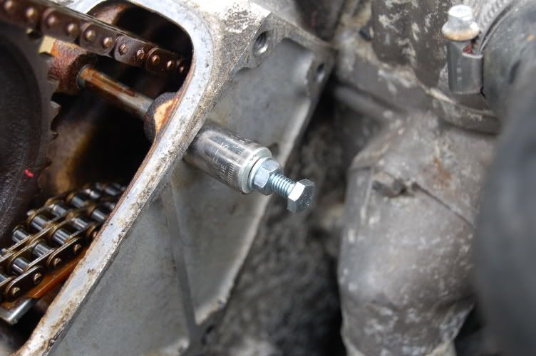 Basically what you have to do is after installing the longer screw with washers, socket into the pin, hold the longer screw with a rachet from spinning and turn the nut clockwise. The screw I used was 6mm diameter, 1mm pitch and 50mm long The second recommendation is on the triple square (XZN) bit. DO NOT GET IT FROM AUTOZONE OR EBAY!! Maybe it was my fault but after I was done loosening the head bolts, this is what happened to it. 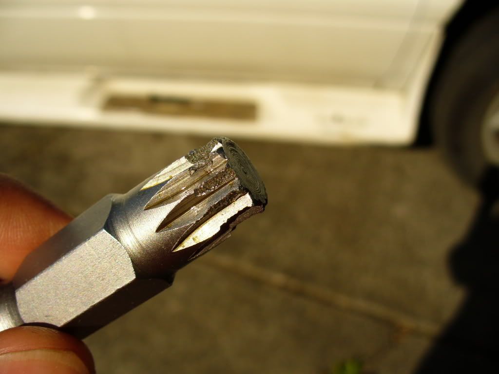 Instead get SK or SnapOn. 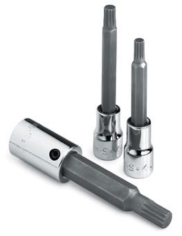 perhaps I should have checked and see how the bit was holding up after each use. I'm going to have to clean up all the metal pieces in the head tomorrow from the autozone crap. thanks Autozone!!
|
|
#12
03-22-2008, 05:20 AM
|
||||
|
||||
|
I must say this was a very informative post regarding the head gasket replacement on the E320. Just a couple of notes here to add, as I just did this on my 94 E320.
1. Yes the part about the vacuum hoses under the intake manifold, definitely order them before starting the job, they are available here on the fastlane parts list, they are listed as "breather tubes". The clamps that secure these lines under the intake are pain in the A** to remove as well, this took longer than a lot of the other disassmbley in order to remove the head. I completely agree, just cut these tubes in half and save yourself an hour or so trying to disconnect them while trying not to break the connections at the intake manifold. I ended up changing the squeeze clamps when I replaced the tubes (hoses) with regular hose clamps with a screw to tighten that I could access from the top of the intake manifold. 2. The EGR tube is also quite a pain in the butt, just make sure you remove the retaining bolts at the left side of the head (it connects to the black bracket used to lift the head), the next retaining bolt is at the oil filter assembly and the last bolt it at the throttle actuator I believe. I discovered all these bolts as I began to slowly lift the head off the engine block. 3. The rear head bolt on the left side of the head cannot be inserted without installing it into the head before lowering the head onto the engine block. I ended up inserting the bolt and then holding it up with some duct tape so it would not portrude out of the bottom of the head as I positioned the head onto the block. Trust me on this one, you cannot get the bolt into the head if you lower the head onto the block first, the firewall will prevent it. 4. Remove the air filter box, this will make the process of re-installing the chain tensioner much, much easier. 5. Last but not least, I know it says in this post on the first part you can leave the accesory belt in place, but in the end you end up loosening it anyway to remove the air pump. Loosening the belt and removing the air pump and its plumbing is much easier to do than trying to remove the air pump plumbing with the air pump in place and the belt still in place. In the end all turned out well for me and the engine fired up immediately on the first try. I was very cautious and a bit nervous and triple checked that I had the cam gears aligned properly as well as manually turning the engine through 2 revolutions before I even thought of turning the key, the last thing I wanted to hear was valves hitting pistons. I must say overall this was a very, very good post. Just wanted to add a couple of my own observations when doing this job in order to make this a bit easier for the next one of us that decides to tackle this job.
__________________
1999 SL500 87K1994 E320 112K 1998 Ford Ranger - the daily driver 274K and no major repairs (an indestructible truck) 1978 Pontiac Trans Am 110K 1977 Pontiac Trans Am 130K 1999 SL500 87K (the garage queen, only out in the summer)
|
|
#13
03-22-2008, 06:49 AM
|
||||
|
||||
|
One last note, it anyone needs a pic of the head layout with the bolt tightening sequenence PM me and I can send it to you. I will try to post the pic soon. Also in order to avoid any mistakes or omissions while tightening the head bolts I made a "checklist", bolt by bolt in order to make sure I got the sequence right and to do it right the first time.......to check off each bolt at a time, first with the initail 41 ft/lbs, the first angle torque and then the second angle tourqe. With 14 head bolts it is easy to lose track.
__________________
1999 SL500 87K1994 E320 112K 1998 Ford Ranger - the daily driver 274K and no major repairs (an indestructible truck) 1978 Pontiac Trans Am 110K 1977 Pontiac Trans Am 130K 1999 SL500 87K (the garage queen, only out in the summer)
|
|
#15
09-17-2009, 04:04 PM
|
|||
|
|||
|
71Rcode,
I was reading your thread where you are explaining the timing being one tooth off, and how Arthur Dalton had sent you a PDF file that explained it all, would you mind emailing me that PDF file? The allen wrenches were not lined up? Is that how you determined you were one tooth off? Thanks in advance!!! email address: jcberean@gmail.com John...
|
 |
| Bookmarks |
|
|


 Hybrid Mode


