Refreshing the Alternator
on the 1981 300D (OM617 W123)
by Army
02/24/11
Refreshing the Alternator on an OM617
Having recently written a DIY for a starter motor I thought I'd post the following for an alternator. I'd like to point out that much like a starter motor, these units can be refreshed / rebuilt / overhauled with comparative ease.
I found the following useful information on the internet:-
this is good for general rebuild advice,
which is good for electrical testing information (though I suspect some of the numbers are a bit out!)
for information concerning air drying varnish.
My alternator turned out to be a re-manufactured Bosch unit. Sorry I don't know the part number for the whole assembly, and I don't even know how much current it is meant to produce. Perhaps someone will be able to identify it for me?
Taking it apart (1)
Once you've got the alternator off of the engine – which I understand some people find difficult – the chances are you'll have found out that some bolts and nuts are not meant to move! If you are struggling with alternator removal take a look at the pictures below. Perhaps they will help.
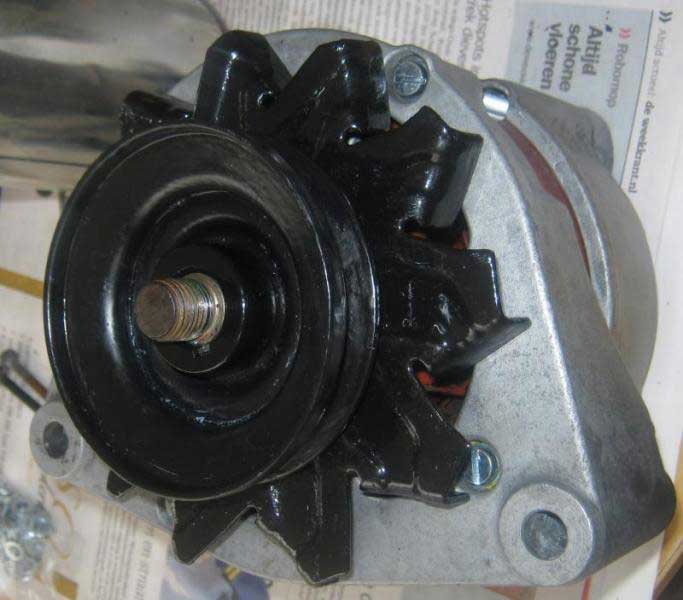
Start by removing the nut from the pulley. It is a good idea to leave the adjustable mounting bracket on the side of the alternator in place for this, as you can use it to stop the fan from rotating whilst undoing the nut (22mm socket).
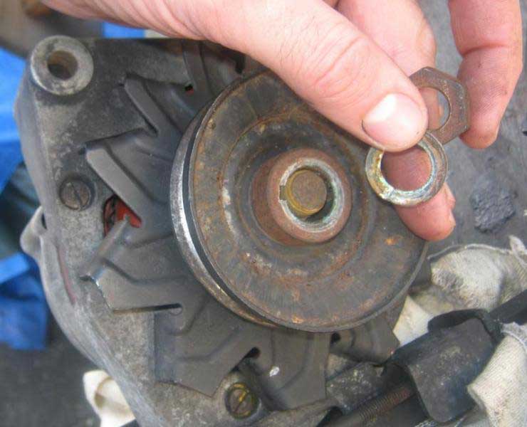
If this doesn't work then I recommend trying to stop the pulley from turning with a strap wrench before resorting to clamping it in a vice. Whatever you do don't damage the pulley – if you have a knackered pulley then you are better off replacing it. A pulley needs to be straight and true otherwise you'll have trouble with V belt tension, vibration, bearings, V belt durability etc etc etc...
Under the nut on the pulley you'll find a split washer. Remove this, a thick spacer, the pulley, a thin spacer,

...and the fan from the alternator.
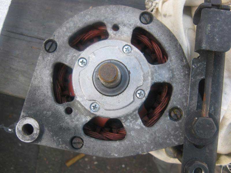
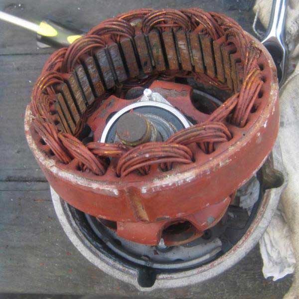
Underneath all of this stuff you'll see that there are two sets of four screws.

The inner set hold a bracket that helps to locate an inner bearing assembly on the rotor, and the outer set (four long screws) hold the two aluminum casings in place on either side of the stator.
Unlike in the OM617 starter motor the armature in this alternator is a stator – it doesn't turn. Whilst at first glance this alternator seems quite similar to an electric motor / dynamo it is subtly mechanically different as it does not have a commutator. Instead it has a slip ring assembly.
When the rotor is turned an alternating current (AC) is induced. To obtain direct current (DC) the AC is converted to DC through a set of diodes that are positioned in the plastic assembly at the back of the unit – at the opposite end of the pulley.
See THIS ARTICLE for more information regarding the workings of alternators.
Taking it apart (2)
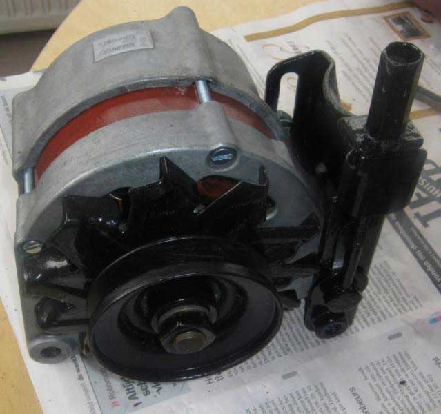
Once you've removed all of the parts off of the pulley shaft, I recommend removing the adjusting mount assembly. Unscrew the V belt tension adjusting captive nut...
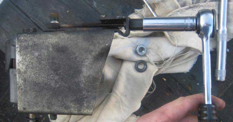
...and pull the adjusting screw thread from the mount.
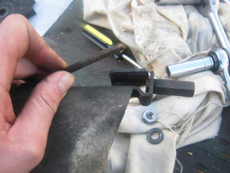
Here is a picture of the mounting bracket when removed from the alternator.

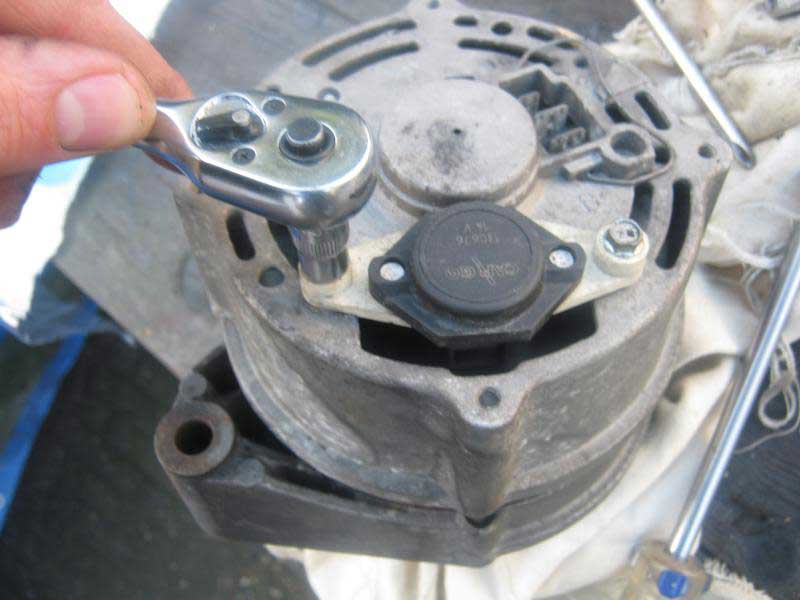
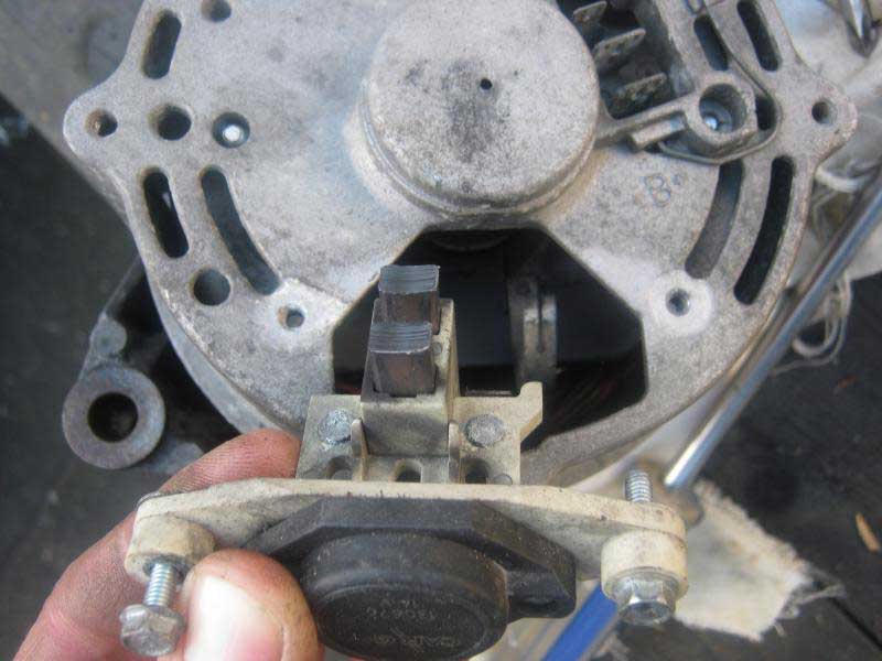
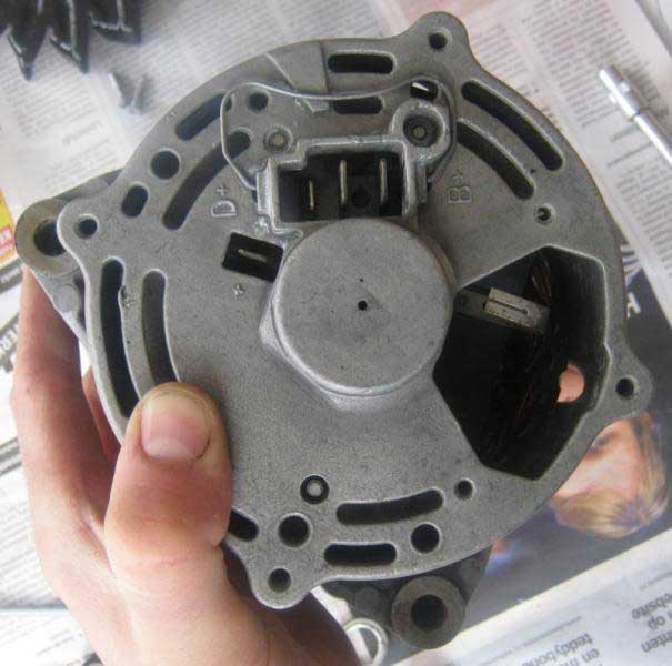
Next I removed the assembly that contains the brushes on the back of the alternator (next to the electrical connector sockets) so that I didn't damage it. You'll need a 7 mm hex socket for this.
I then removed the two sets of four screws mentioned previously, so I could split that casing.
I was lucky in that I only had to drill out one screw!
Taking it apart (3)
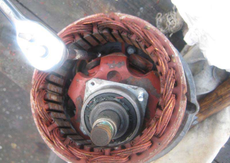
Take your time splitting the casing once you've removed the screws. If you need to pry the casing apart please be careful with how you use your screw drivers! Start by taking off the casing at the front (pulley end)...
...and you should be able to see the rotor inside. If you can, lift the rotor out. Mine was a bit stuck so I had a little bit more trouble removing the back part of the casing. With care you can “ping†the stator away from the back casing...
...and access four 7mm hex head screws that hold the plastic electrical assembly housing (which contains the diodes etc) in the back cover.
You need to be careful at this stage otherwise you'll have to do some soldering! Three wires run from the armature to this electrical assembly – don't break them!
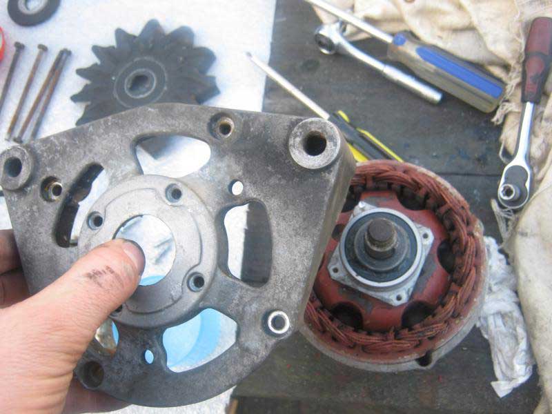
You should now be able to pull the stator (and rotor if it was stuck) away from the back casing.
Electrical Testing
For this you'll need a multimeter that can measure resistance.
I followed the advice in THIS LINK under the section “TESTING & REPAIRâ€.
Diode Assembly
1. Place ohmmeter scale on x100 scale connect ohmmeter leads across "B+" terminal and 3 stator terminals one at a time, reverse leads, ohmmeter should indicate continuity in one direction only.
2. Reconnect ohmmeter leads across negative and 3 stator terminals one at a time.
Reverse leads; ohmmeter should indicate continuity in one direction only.
3. Connect ohmmeter leads across "D+" terminal and 3 stator terminals one at a time.
Reverse leads, ohmmeter should indicate continuity in one direction only, if diodes are found to be defective, replace the diode assembly.
Fig. 3: Diode Assembly Test Diode assembly for 55 amp alternator is shown, others are similar.
1. Place ohmmeter on lowest scale, connect ohmmeter across stator leads, resistance between leads should be 14 15 ohms for 55-amp alternator and .09 10 ohms for 65 through 90 amp alternators, if resistance is incorrect, stator has open or shorted windings and must be replaced.
2. Place ohmmeter on X 1000 scale. Connect ohmmeter between stator core and stator lead, no continuity should exist, if continuity exists, stator is grounded and must be replaced.
1. Place ohmmeter on lowest scale, connect ohmmeter across slip rings, resistance should be 3 4-3.75 ohms for 55 amp alternator and 2.8 3.1 ohms for 65 through 90 amp alternators.
2. If resistance is too low, rotor has short circuit and it must be replaced if resistance is infinity no continuity, rotor has open circuit and must be replaced.
3. Place ohmmeter on x1000 scale, reconnect ohmmeter between either the slip ring and rotor core, no continuity should exist, if continuity exists, rotor is grounded and must be replaced.
To be honest the diode testing went well. Then, when I got past where it says “Fig. 3:...†I got nonsensical readings from my multimeter. I'm not 100% certain that the numbers quoted in this article are correct. The authors conversion from lbs-ft to Nm at the end of the article is incorrect. Anyway if anyone else follows this advice I'd be interested to hear how it went.
As my alternator was working fine before I took it apart, I guessed everything was still OK so I carried on regardless – as I'm sure you can tell I'm not really electrically minded – I don't have the patience for those bloody multimeters!
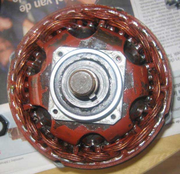
Assessing condition
Look for any obvious damage such as evidence that the rotor has been dragging on the stator. Check out the bearings at both ends of the rotor. Make sure that they spin freely. If they don't you'll have to replace them by pulling them off with a puller. If you can, get hold of a proper bearing puller rather than a more common two or three leg puller, as you are more likely to be able to remove the bearings in one piece. Two or three leg pullers tend to just remove the outer races leaving you to find a solution for the inner races! The advice in THIS LINK is to fit new bearings with the open side of the seal towards the rear of the alternator – so that is away from the pulley end where muck and debris gets sucked into the unit from the fan.
I was lucky enough not to need new bearings.
Just in case this information is useful - here are the bearing sizes
Back bearing (not the pulley end) OD = 32mm, ID =12mm and thickness =10mm
Front bearing (pulley end) OD =47mm, ID = 17mm and thickness = 14mm
Cleaning and finishing
I thought my armature was pretty rusty so I went at it with a flap sanding wheel (bought at great expense).
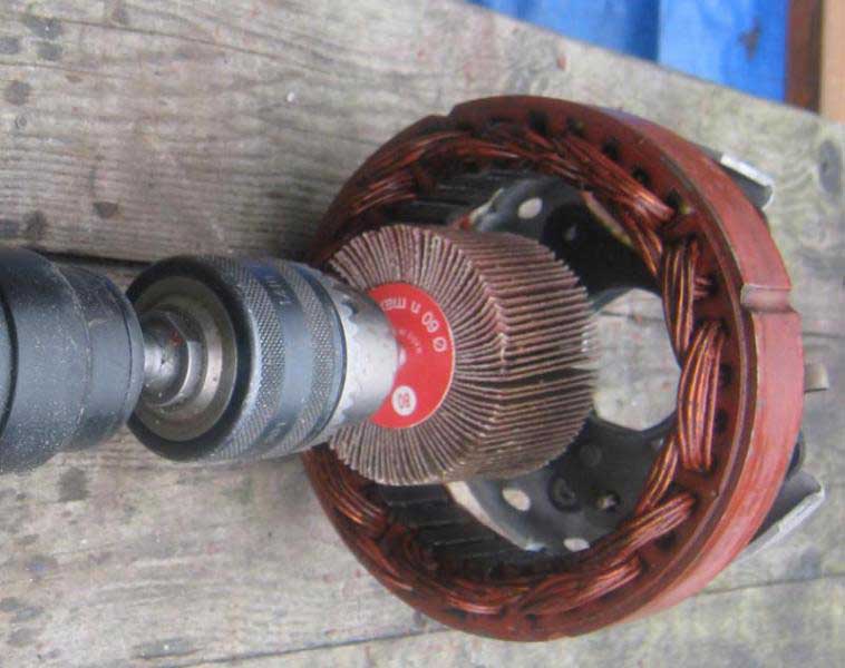
Try not to remove too much metal here as the clearance between the rotor and the stator needs to remain quite small. If anyone has got the official clearance for this it would be great to know – I couldn't find it.
As for the rest of the alternator, I stripped the mounting bracket and painted it with black POR15, and I cleaned the internals with brake cleaner.
Now is the best time to clean the electric contacts on the back of the alternator.
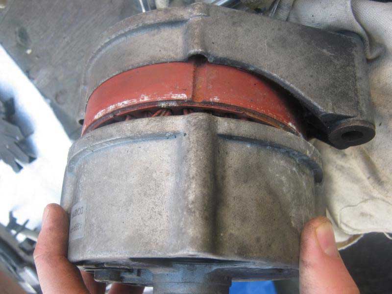
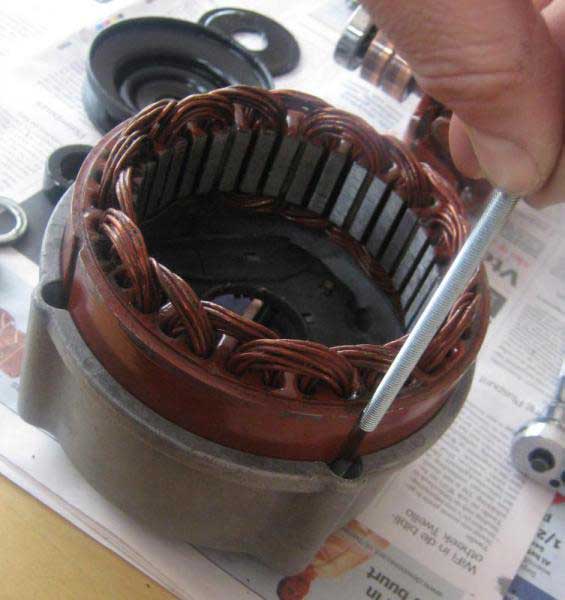
The stator and rotor in the alternator are treated at point of manufacture to a coating of electrically insulating varnish that I understand is baked onto the surfaces. This is the red oxide paint-like substance you can see in the pictures. I was advised to try and preserve as much of the original varnish as possible as it is better at insulating than the air drying varnish that is readily available to the DIY motor mechanic. Therefore I removed the flaking bits with gentle use of a screw driver and sand paper, then I cleaned up the areas with brake cleaner followed by an application of Eastwood pre-paint solvent.
Prior to applying the air drying varnish I masked up the rotor and the stator.

Please note: I masked the armature for when I applied many coats of varnish over the whole stator. Once finished I removed the masking tape and applied two thin coats over the armature so that I didn't mess up the clearance between it and the rotor.
The message is – don't spray on too much varnish on either the rotor or the stator areas where they will be in close contact. If they get too close they can heat up and breakdown the insulating varnish.
Assembly (1)
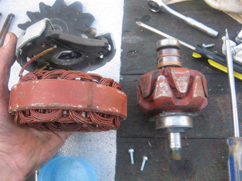
Here's a picture of all of the bits ready to go back together.
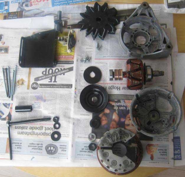
You can see that I could only find the clear air drying varnish which is why some parts look a bit patchy.
Start by assembling the electrical connection assembly (the bit with the diodes) in the back outer casing.

If your rotor was stuck when you took the alternator apart you'll appreciate how easy it is to reach the four 7mm hex head screws.
Make sure that before you push the stator into the back outer casing that you align the recesses in the stator with the bolt holes in the casing.
Next fit the rotor – push down so that the bearing sits properly in the back outer casing. The rotor coils should be in line with the armature on the stator.
Assembly (2)
You can now fit the other half of the outer casing in position, however, you first need to get the correct orientation. On my alternator, the large hole for the brush assembly on the back cover was positioned to the right hand side of the two mounting lugs on the front casing (viewed from the back of the alternator).
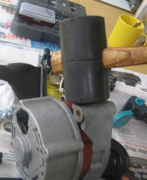
Gently push the front outer casing onto the stator. You may have to adjust the position of the mounting lugs on the front outer casing – so that the bolt holes line up with the recesses in the stator. Gently tap the casing with a rubber mallet.
Push the two outer casings firmly onto the stator by applying force from a clamp. Ensure the joining edges of the casings and the stator remain parallel to each other whilst you are applying the clamping force. You will probably have to stop and reposition the clamp several times to make sure that the casings do not go on askew.
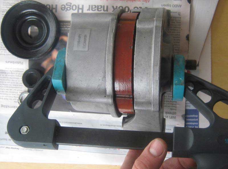
When pushing the casings together try to image a force that is less than standing on the alternator and jumping up and down on it! You don't want to be too rough – if you apply too great a force you will unseat or damage the bearings.
At this point it is a good idea to check that the rotor can still turn. It should spin freely – there should NOT BE EVEN A HINT OF ANYTHING AT ALL SCRAPING AGAINST IT!
If this is not the case, now is the time to rectify it; take it all apart again and find out what is wrong.
If all is well, and the rotor spins freely, continue by fitting the two sets of four screws that fix the front outer casing in position. Tighten the long screws down in stages so that you do not skew the two casings together.
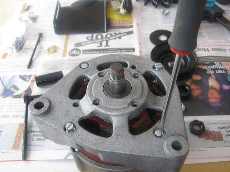
Again you need to make sure that the rotor spins freely.
Again, if it does not you need to rectify the problem.
If all goes well the rotor shaft should just sit proud of the front outer casting.
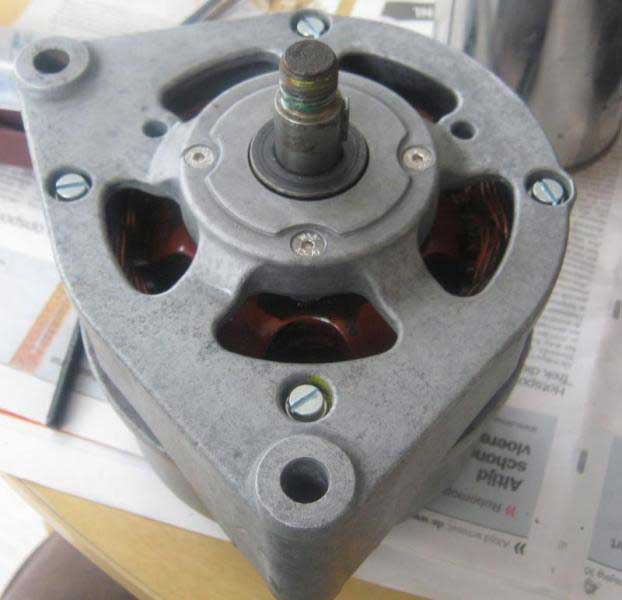
This is important as the fan needs to clear the casing.
Assembly (3)
You can now fit the alternator brush assembly...

...and the fan, the thin spacer, the pulley, the thick spacer, the split washer and the securing nut.
Tightening the nut can be done by holding the pulley fast with a strap wrench. The quoted torque in THIS LINK is 23 – 29 lbs-ft that's about 31 – 39 Nm.
Fitting the mounting assembly is the reverse of removal.
Final comments
With the exception of the problems I had following the instructions of the electrical testing, I found this to be a very straightforward job.
However, I'm not happy with the standard of finish on the mounting bracket and the alternator fan. POR15 to my mind never looks that good on flat surfaces. If I decide to keep with my planned all in black finish for my engine I will probably redo these bits with a more factory-like black – POR15 is just too shiny. I'm still in two minds whether I should paint the visible side of the stator in black too...
...anyway, the plan is to see if it all works when I get my engine back together – and then perform the rest of the electrical testing procedure in (LINK). Fake cadmium coatings and or factory finish black can wait for now.
Discuss this DIY here.
-Army
CategoryDiy