The book (FSM) says that the four little cogs that go in the central part of the differential should be fitted with shims so that there is a friction of 40 to 90 Nm.
This seems like a mental amount of friction to me but I haven't been able to find any information that this is in fact an incorrect value. It is consistently used in the FSM and WIS so I guess it is OK.
The way to adjust this friction is by shimming the position of the cogs that are attached to the output shafts of the differential (these are defined as side cogs in post #39). The other two cogs that idle between have the PTFE bearings discussed above (these are defined as spider cogs in post #39)
The FSM doesn't really give any advice other than to use the special tool mandrel to those two idler (spider) cogs and add or remove the shims on the other cogs (side cogs) accordingly.
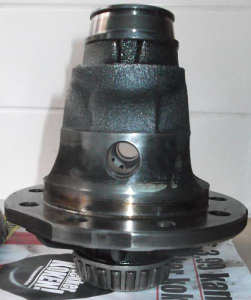
I figured that if you place the end of this inner casing on the crown wheel (ring gear) end and assemble the four cogs (spider and side cogs) with the shims you already have then you can measure any gap with feeler gauges
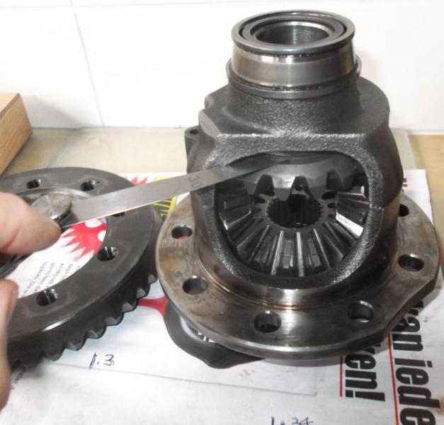
Once you've got this gap measured - be careful these cogs rock and wobble a bit when loosely assembled with out the special tool mandrel (!!!!) then you can estimate which one of the shims you need to buy from the dealer.
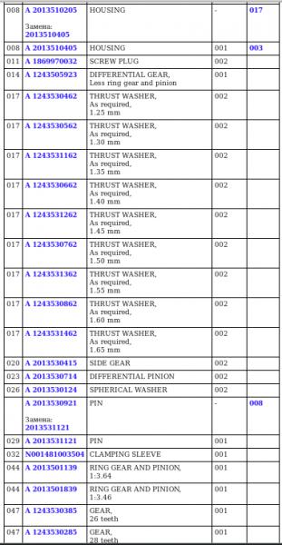
These thrust washers / shims are all item numbers 17 in this picture

As you can see the shims are available in steps of 0.05mm starting at a thickness of 1.25mm going all the way up to 1.65mm
To give you an idea of where to add the shims - on top of the "upper cog" (orientation as shown in picture above - not the same as when fitted to car!) or under the "bottom cog" spin the casing 90 degrees to see visually whether the pin in the two idler (spider) cogs will slide on through =>