Parts Catalog Accessories Catalog How To Articles Tech Forums
Call Pelican Parts at 888-280-7799
Shopping Cart Cart | Project List | Order Status | Help


Go Back   PeachParts Mercedes-Benz Forum > Mercedes-Benz Tech Information and Support > Diesel Discussion

Reply
 
LinkBack Thread Tools Display Modes
  #1  
Old 12-29-2014, 12:08 AM
Ben Froelich's Avatar
Excelsior!
 
Join Date: Jul 2013
Location: California
Posts: 12
Cruise Control Project

Hello Everyone! First of all, I want to say thank you to everyone who’s posted on the forum so far. I haven’t had to make many posts because of the quality and quantity of information on this site! I also want to thank James Dean for the info he provided about the CC in these vehicles.

The cruise control amp on my 80 300D was non-functional when I bought the vehicle. After touching up solder joints, replacing electrolytic caps, and trying to reverse engineer the design, the frustration built enough to motivate me to make my own more modern CC amp/controller board. Also, I haven’t fabbed a circuit board before, so it’s a great learning opportunity. I want to share it here and see if anyone has feedback or ideas.

System Overview:
The original Mercedes system was comprised of an accelerator linkage actuator, a speed sensor attached to the speedometer, a control stalk on the steering wheel, and a cruise control amplifier/controller. The amplifier took in the speed sensor signal and the control stalk commands, and controlled the speed using the accelerator actuator. I’m lazy and want to keep as much of the system original as possible, so I’m using the stock speed sensor and actuator for now. I even sized the circuit board and connectors to fit inside the original aluminum CC amp box (the one above the brake pedal behind the kick panel). I simply desoldered the connector from the old board and soldered it to the new one, as shown in the photos. A microcontroller (µC) is the brains of the system.
The original system included a latching-relay-based safety circuit, which I mimicked in my design; I don’t trust my homebrew µC code enough to give it free reign of my car, regardless of how slow it is! Below are some pictures, followed by some tech details.

Block Diagram:


Out with the old and in with the new!


Close up of CC board, see if you can find the "oops-I-made-a-mistake-on-a-footprint" jumper wire


Bottom of board:


The details about the altered system:

Speed Sensor:
I didn’t modify the original speed sensor at all. It’s a pretty simple device, basically an inductive sensor that produces a sinusoid with a frequency approximately 2.5x the vehicle speed. E.g. if the vehicle is traveling at 50MPH, the speed sensor oscillates at ~125Hz.

The Brains:
I used an MSP430G2553 16-bit microcontroller because I have a Launchpad development kit that I’m using to program and debug the µC’s. Also, it runs well on a 3.3V rail and has excellent free development tools, such as an impressive debugger and decent sample code. Currently, I have a finite state machine running on the board, see state diagram below. I might change this in the future to clean up the states.
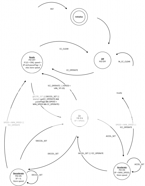


Currently, the controller calculates a value proportional to the reciprocal of vehicle speed, by measuring the time between speed sensor pulses. It then runs this through a proportional algorithm to keep a constant speed. This configuration has two major disadvantages. First, using the reciprocal of vehicle speed means that the controller scales down its output at higher frequencies, because it interprets the difference of 10MPH and 20MPH as 2x, but the difference between 50MPH and 60MPH as 1.2x. This manifests itself by poor speed regulation at high speeds, and overly aggressive response at low speeds. Second, proportional control alone does not eliminate steady state error, meaning that when the controller is set to keep 60MPH, it will settle out to 55MPH, for example. I’m working on both of these problems currently.

The accelerator-linkage actuator:
In my vehicle, I have the old-school vacuum actuator. It’s response to voltage and current is fairly non-linear, i.e. it is either full or no "throttle", with a very small region where it provides adjustable "throttle". This is going to be difficult to use in this application and may cause instability, so I might upgrade to one of the more modern servo actuators if I can’t get a stable response by tuning the control loop. I’m driving it via pulse width modulation at 6.7kHz. I believe the original design drove the actuator using a DC voltage, but PWM is more efficient and simple to implement in a digital circuit.

Power Stage:
The power stage on the first spin of the board includes a switching regulator and an input protection circuit. The function of this circuitry is to provide 3.3VDC to the µC and related circuitry using the 12V battery supply. Apparently, there are some nasty transients in automotive power systems, such as load dump and reverse polarity conditions (see http://www.littelfuse.com/~/media/electronics_technical/application_notes/varistors/littelfuse_suppression_of_transients_in_an_automotive_environment_application_note.pdf). These would trash a normal power circuit, so I included a robust power protection circuit. This circuit prevents voltage above 18V or below 10V from reaching the 12V->3.3V converter. Also, I had never laid out a switching DC-DC converter, so I decided to use one on the first spin of the board. If I do another spin of the board, I’ll probably use a simpler, but less efficient linear regulator and less aggressive protection circuitry.

I designed the PCB using KiCAD and had it fabbed using OSH Park. Both worked very well. Hit me up if you want design files. google email benfroelich.

__________________
http://badges.fuelly.com/images/smallsig-us/353045.png- '80 300D naturally aspirated, 147k
Reply With Quote
  #2  
Old 12-29-2014, 01:26 AM
mach4's Avatar
Registered User
 
Join Date: Jul 2011
Location: San Diego County, CA
Posts: 2,736
Very interesting project. I'd be interested in hearing a bit more about your power circuit. When I did my Arduino/Bluetooth/Android engine instrumentation project I used a variable power supply module capable of handling up to 50 volts to output 7.2 volts to the Arduino which has an on board power supply that can handle up to about 12 volts continuous and 18 for short periods that provides regulated 5 volts to the micro-controller.

The system has been running for the better part of a year with no glitches so hopefully my solution is adequate to handle the spikes and transients.

I've also got a voltage measuring circuit on board that can handle up to 55 volts without putting the analog port on the microcontroller in danger of blowing.

What are you doing to address the power issues?
__________________
Current Stable
  • 380SL (diesel)
  • Corvette C5
  • Manx
  • Baja Bug
  • F350 Powerstroke
  • Auburn Boattail Speedster replica
Reply With Quote
  #3  
Old 12-29-2014, 02:24 AM
Ben Froelich's Avatar
Excelsior!
 
Join Date: Jul 2013
Location: California
Posts: 12
Quote:
Originally Posted by mach4 View Post
Very interesting project. I'd be interested in hearing a bit more about your power circuit. When I did my Arduino/Bluetooth/Android engine instrumentation project I used a variable power supply module capable of handling up to 50 volts to output 7.2 volts to the Arduino which has an on board power supply that can handle up to about 12 volts continuous and 18 for short periods that provides regulated 5 volts to the micro-controller.

The system has been running for the better part of a year with no glitches so hopefully my solution is adequate to handle the spikes and transients.

I've also got a voltage measuring circuit on board that can handle up to 55 volts without putting the analog port on the microcontroller in danger of blowing.

What are you doing to address the power issues?
Hey Mach4, I saw your awesome project! Very cool and the software and networking is totally beyond me. I went wayyy overkill on this board to and haven't tested it fully yet. I bet your solution is fine. I haven't had much hands-on experience with automotive power supply transients, so I don't know how often load dump etc occur. And it's hard to drive around town with an oscilloscope hooked up to the battery! Maybe I'll do some tests with the car standing still.

Here's what I did on this board. I'll probably use a LDO regulator on the next board because it will significantly reduce component count. Also, I'll only need about 50mA, so 1A is just unnecessarily high. Plus there are some nice automotive LDO regulators out there that provide input protection.


What did your input protection circuitry look like?

Regards,
Ben
__________________
http://badges.fuelly.com/images/smallsig-us/353045.png- '80 300D naturally aspirated, 147k
Reply With Quote
  #4  
Old 12-29-2014, 08:16 AM
jay_bob's Avatar
Control Freak
 
Join Date: Oct 2011
Location: Columbia, SC
Posts: 3,941
Nice work there.

Couple of things I would suggest. I work with generator controls that are essentially the same principle as a cruise control. Instead of trying to maintain a constant road speed we are trying to control frequency via the fuel quantity, and control the voltage via excitation in the alternator. In response to changing load conditions we have to adjust the fuel and excitation to maintain a constant voltage and frequency within prescribed limits.

- As you have noticed Proportional control is not enough to provide proper regulation. You need the Integral and Derivative functions as well. Derivative scales the response action to the rate of change (smaller response for smaller rate of change). Integral dampens out the oscillations as the error swings +/- about the setpoint. Best word for that is "stability" in fact many of the old governors have a control marked that, in reality behind the cover it is performing an Integral function mechanically.

- I would definitely ditch that vacuum actuator. I have heard that it is not very reliable and can even lead to runaway. You should be able to locate a VDO actuator out of the 81+ 123/126 models and adapt it. The bonus is that the VDO has a 3.5 k ohm feedback pot built in.

- Make sure the VSS signal is as clean as possible (garbage in = garbage out). I know the later models they used a Hall sensor on the back of the speedometer. Not sure if the 1980 used that sensor or just a magnet and a reed switch. I know on the 124s it is a separate module that can be replaced. Can't remember on the 123s how they arranged it.

Also make sure your speedometer cable is in good shape and is running smoothly. If your speedometer needle is jumpy you are doomed ever getting it to regulate.

I wish we had the tools back in the day to do prototyping like that. We were stuck with wire wrap sockets and probing around with a scope to get it working.
__________________
The OM 642/722.9 powered family
Still going strong
2014 ML350 Bluetec (wife's DD)
2013 E350 Bluetec (my DD)

both my kids cars went to junkyard in 2023
2008 ML320 CDI (Older son’s DD) fatal transmission failure, water soaked/fried rear SAM, numerous other issues, just too far gone to save (165k miles)
2008 E320 Bluetec (Younger son's DD) injector failed open and diluted oil with diesel, spun main bearings (240k miles)

1998 E300DT sold to TimFreeh
1987 300TD sold to vstech
Reply With Quote
  #5  
Old 12-29-2014, 09:39 AM
mach4's Avatar
Registered User
 
Join Date: Jul 2011
Location: San Diego County, CA
Posts: 2,736
Hmmm, you've got me thinking about redoing my system now on a PCB. I've got access to a CNC mill so assuming the KICAD outputs a DWG file I could fab up a PCB rather than use a breadboard. I can't think of any more inputs needed but stubbing in connectors to the other analog ports would be trivial.

I'll be watching your project with interest - thanks for the post.
__________________
Current Stable
  • 380SL (diesel)
  • Corvette C5
  • Manx
  • Baja Bug
  • F350 Powerstroke
  • Auburn Boattail Speedster replica
Reply With Quote
  #6  
Old 12-29-2014, 10:03 AM
mach4's Avatar
Registered User
 
Join Date: Jul 2011
Location: San Diego County, CA
Posts: 2,736
Since my only experience with micro controllers is Arduino, I got to wondering whether anyone in the Arduino community had ever built a cruise control. I was a little surprised to find that there was sparse hard info but a bit of interest and speculation on how it might be done. One person suggested the use of PID code for control. It turns out there is a PID (proportional integral derivative) library for the Arduino - PID Library It's possible some of the routines could be adapted or appropriated for your project.
__________________
Current Stable
  • 380SL (diesel)
  • Corvette C5
  • Manx
  • Baja Bug
  • F350 Powerstroke
  • Auburn Boattail Speedster replica
Reply With Quote
  #7  
Old 12-29-2014, 02:01 PM
Ben Froelich's Avatar
Excelsior!
 
Join Date: Jul 2013
Location: California
Posts: 12
Quote:
Originally Posted by mach4 View Post
Since my only experience with micro controllers is Arduino, I got to wondering whether anyone in the Arduino community had ever built a cruise control. I was a little surprised to find that there was sparse hard info but a bit of interest and speculation on how it might be done. One person suggested the use of PID code for control. It turns out there is a PID (proportional integral derivative) library for the Arduino - PID Library It's possible some of the routines could be adapted or appropriated for your project.
Hey Mach4, yes that is a very nice library. He's got a very nice write up too. I'm going to try PI control for now, basing it off of his library.
__________________
http://badges.fuelly.com/images/smallsig-us/353045.png- '80 300D naturally aspirated, 147k
Reply With Quote
  #8  
Old 12-29-2014, 02:03 PM
Ben Froelich's Avatar
Excelsior!
 
Join Date: Jul 2013
Location: California
Posts: 12
Quote:
Originally Posted by mach4 View Post
Hmmm, you've got me thinking about redoing my system now on a PCB. I've got access to a CNC mill so assuming the KICAD outputs a DWG file I could fab up a PCB rather than use a breadboard. I can't think of any more inputs needed but stubbing in connectors to the other analog ports would be trivial.

I'll be watching your project with interest - thanks for the post.
Ya, I was surprised how well the board turned out using KiCAD and OSH Park. I'm sure you could get great results with your mill.
__________________
http://badges.fuelly.com/images/smallsig-us/353045.png- '80 300D naturally aspirated, 147k
Reply With Quote
  #9  
Old 12-29-2014, 02:21 PM
Ben Froelich's Avatar
Excelsior!
 
Join Date: Jul 2013
Location: California
Posts: 12
Quote:
Originally Posted by jay_bob View Post
Nice work there.

Couple of things I would suggest. I work with generator controls that are essentially the same principle as a cruise control. Instead of trying to maintain a constant road speed we are trying to control frequency via the fuel quantity, and control the voltage via excitation in the alternator. In response to changing load conditions we have to adjust the fuel and excitation to maintain a constant voltage and frequency within prescribed limits.

- As you have noticed Proportional control is not enough to provide proper regulation. You need the Integral and Derivative functions as well. Derivative scales the response action to the rate of change (smaller response for smaller rate of change). Integral dampens out the oscillations as the error swings +/- about the setpoint. Best word for that is "stability" in fact many of the old governors have a control marked that, in reality behind the cover it is performing an Integral function mechanically.

- I would definitely ditch that vacuum actuator. I have heard that it is not very reliable and can even lead to runaway. You should be able to locate a VDO actuator out of the 81+ 123/126 models and adapt it. The bonus is that the VDO has a 3.5 k ohm feedback pot built in.

- Make sure the VSS signal is as clean as possible (garbage in = garbage out). I know the later models they used a Hall sensor on the back of the speedometer. Not sure if the 1980 used that sensor or just a magnet and a reed switch. I know on the 124s it is a separate module that can be replaced. Can't remember on the 123s how they arranged it.

Also make sure your speedometer cable is in good shape and is running smoothly. If your speedometer needle is jumpy you are doomed ever getting it to regulate.

I wish we had the tools back in the day to do prototyping like that. We were stuck with wire wrap sockets and probing around with a scope to get it working.
Thanks for the input. I'm going to implement a PI controller next and see how good of a response I can get.

Will look into getting a servo actuator as well.

The sensor is just a coil and I think some metal core. There is a magnetic ring with 4 poles that rotates with the speedo cable. I think the changing magnetic field from the magnet through the coil produces the sinusoid on the coil. A very simple, effective sensor.

The hardware clips this VSS sinusoid using a zener diode and resistor, producing a pseudo-square wave. The code takes this signal, debounces it, and take a 2 sample average to get the period. The signal is pretty clean and the VSS shares the same ground as the CC controller.
__________________
http://badges.fuelly.com/images/smallsig-us/353045.png- '80 300D naturally aspirated, 147k
Reply With Quote
  #10  
Old 12-29-2014, 04:25 PM
mach4's Avatar
Registered User
 
Join Date: Jul 2011
Location: San Diego County, CA
Posts: 2,736
I'm going to guess that the signal you're getting is from a variable reluctor with no magnets involved. That would make it the same as the signal from the electronic speedometers that use a VR sensor on the transmission.

I think you'll be fine using the speed signal that comes out of the speedometer, but if not, you can create a very stable signal using the components that MB uses on their electronic speedos. Here's a link to the strategy I used initially on my OM617->R107 swap. It's since been decomissioned after swapping the 722.4x transmission with a 722.3x transmission. Both stock transmissions have a mechanical speedometer, but I was able to swap in the tailcone from the 722.3x transmission from the 380SL that was setup for the electronic speedometer (couldn't use the transmission itself because the starter is on the wrong side and the ratios are wrong). You could potentially use a Hall effect sensor as well, but I think you'll be just fine with the current signal.
__________________
Current Stable
  • 380SL (diesel)
  • Corvette C5
  • Manx
  • Baja Bug
  • F350 Powerstroke
  • Auburn Boattail Speedster replica
Reply With Quote
  #11  
Old 01-18-2015, 07:41 PM
Ben Froelich's Avatar
Excelsior!
 
Join Date: Jul 2013
Location: California
Posts: 12
Update. Started a new job, so I won't have much time to work on this project. Also, other stuff keeps breaking on ol' Stinky.

jay_bob is right, I couldn't get good control with the vacuum actuator, It's really an ON-OFF switch in response to the PWM signal I was sending it, making the system a bear to control. I wonder if they used a current source to control it in the original circuitry. I pulled a servo actuator from a lexus. 7 pins, same config as the VDO servo actuator.
__________________
http://badges.fuelly.com/images/smallsig-us/353045.png- '80 300D naturally aspirated, 147k
Reply With Quote
  #12  
Old 01-19-2015, 12:34 PM
jay_bob's Avatar
Control Freak
 
Join Date: Oct 2011
Location: Columbia, SC
Posts: 3,941
Quote:
Originally Posted by Ben Froelich View Post
Thanks for the input. I'm going to implement a PI controller next and see how good of a response I can get.
I think you are going to find that you are not going to have decent response when you are trying to drive on a road that is not level if you don't include D control.

Here is an example from what I do at work:

When we are doing commissioning on our generator systems, we use a load bank (think a GIANT forced air electric heater) to simulate load on the generator. If the governor's D paramter is not set correctly, then the generator has terrible response to changing load conditions. We prove this by going from 50-100-50 percent load quickly to see how long it takes the generator to match the new load (controlled by D) and settle down from the disturbance (controlled by I). The P parameter only gives us a coarse relationship between %fuel and %load, it scales the output of the controller to the governor since this is just a straight line. All the while we have to maintain 480 V (or higher, we often have 4.16 or 13.8 kV generators ) and 60 Hz. We have to be settled back down to a certain percentage of nominal within a couple of cycles (typically 3 to 5 cycles or 50-80 ms on a 60 Hz basis).

The 50-100-50 test is the same thing that happens with a car cruising on a flat road, encountering a hill, and then cresting that hill. Although that is more like 50-100-10 (depending on the steepness of the grade).
__________________
The OM 642/722.9 powered family
Still going strong
2014 ML350 Bluetec (wife's DD)
2013 E350 Bluetec (my DD)

both my kids cars went to junkyard in 2023
2008 ML320 CDI (Older son’s DD) fatal transmission failure, water soaked/fried rear SAM, numerous other issues, just too far gone to save (165k miles)
2008 E320 Bluetec (Younger son's DD) injector failed open and diluted oil with diesel, spun main bearings (240k miles)

1998 E300DT sold to TimFreeh
1987 300TD sold to vstech
Reply With Quote
  #13  
Old 02-08-2015, 11:31 PM
Ben Froelich's Avatar
Excelsior!
 
Join Date: Jul 2013
Location: California
Posts: 12
Quote:
Originally Posted by jay_bob View Post
I think you are going to find that you are not going to have decent response when you are trying to drive on a road that is not level if you don't include D control.

Here is an example from what I do at work:

When we are doing commissioning on our generator systems, we use a load bank (think a GIANT forced air electric heater) to simulate load on the generator. If the governor's D paramter is not set correctly, then the generator has terrible response to changing load conditions. We prove this by going from 50-100-50 percent load quickly to see how long it takes the generator to match the new load (controlled by D) and settle down from the disturbance (controlled by I). The P parameter only gives us a coarse relationship between %fuel and %load, it scales the output of the controller to the governor since this is just a straight line. All the while we have to maintain 480 V (or higher, we often have 4.16 or 13.8 kV generators ) and 60 Hz. We have to be settled back down to a certain percentage of nominal within a couple of cycles (typically 3 to 5 cycles or 50-80 ms on a 60 Hz basis).

The 50-100-50 test is the same thing that happens with a car cruising on a flat road, encountering a hill, and then cresting that hill. Although that is more like 50-100-10 (depending on the steepness of the grade).
Hey jay_bob, thanks for the input. I especially appreciate the example, it helps clarify the need for each parameter. As you recommended, included all three PID terms in the speed controller. Now it's just a matter of tuning them.

But first, I needed an H-bridge to control the new cruise control actuator from the Lexus. Got it kind of working today - proportional control of the actuator arm using the feedback potentiometer built into the actuator. Due to ADC noise, the potentiometer reading fluctuates about 1%. Combined with overshoot from the motor, the controller and actuator oscillate unless I include hysteresis (see code below). I haven't tried averaging the ADC outputs yet but that's in the works. Also, I had to include a massive P term because the motor won't move with PWM duty cycles below about 75%. Will continue tuning.

Can anyone think of a better way to control this without the hysteresis? Also, I stuffed the actuator control code into my debouncing ISR, so the sample period is about 5ms. Does this seem too high? I could move it to another timer and run it less often. The actuator isn't very fast, but does it matter much for proportional control?

Code:
			// Calculate servo output
			servo_error = (servo_desired - servo_actual);
			if(servo_error < 0) {		// if error is negative, reverse servo
				P2OUT |= BIT3;
				P2OUT &= ~BIT4;
				servo_error = -servo_error;
			}
			else {
				P2OUT |= BIT4;
				P2OUT &= ~BIT3;
			}

			if(servo_error < SERVO_LATCH) servo_flag = 1;
			if (servo_flag && (servo_error < SERVO_HOLD)) servo_error = 0;
			else servo_flag = 0;

			TA1CCR1 = servo_error << SERVO_GAIN;
Here's some pics too. Thanks for reading and your input!


__________________
http://badges.fuelly.com/images/smallsig-us/353045.png- '80 300D naturally aspirated, 147k
Reply With Quote
  #14  
Old 02-08-2015, 11:51 PM
Registered User
 
Join Date: Apr 2011
Location: SF, CA, USA
Posts: 935
cool project. thanks Ben, jay_bob, and mach4 for the entertaining posts. i was not aware of the three -factor measure and i wish i had known about it when i wrote some web advertisement balancing algorithms a few years ago (scaling service up or down depending on traffic to spend the ad account at a constant rate over time).

there is another good explanation of the factors on this page:
Controlling the Cruise Control - HowStuffWorks

__________________
'77 240D, 504H, OM617.952, etc.
Reply With Quote
Reply

Bookmarks


Posting Rules
You may not post new threads
You may not post replies
You may not post attachments
You may not edit your posts

BB code is On
Smilies are On
[IMG] code is On
HTML code is On
Trackbacks are On
Pingbacks are On
Refbacks are On


All times are GMT -4. The time now is 03:29 PM.


Powered by vBulletin® Version 3.8.7
Copyright ©2000 - 2024, vBulletin Solutions, Inc.
Search Engine Optimization by vBSEO 3.6.0
Copyright 2024 Pelican Parts, LLC - Posts may be archived for display on the Peach Parts or Pelican Parts Website -    DMCA Registered Agent Contact Page