I recently was left stranded because of a bad connection on one of the old series-loop style glow plugs on my '78 300CD. Determined to never have it happen again, I swapped over to the newer pencil style that still have the larger body on them (Bremi PN 25039). I ran 12awg wire to each plug from a new terminal strip that I mounted on the firewall. However, the 50amp fuse and factory wiring was questionable, as they pulled well over 100amps at start, and only settled out to 50amps or so after 10 seconds. By that the the fuse was smoking hot, and wire warm as well.
To bypass the factory relay I used 12 feet or so of 8awg wire from the starter lug, through the strip fuse holder (with new 80amp fuse) over to an 80amp 12v relay I mounted in the relay box on the driver's side wheel arch. I then spliced on a couple 1/4" terminal connectors to the original glow power wire and used it to activate the relay coil. This worked well for at least firing the plugs but I still don't trust the old glow relay, as glow time/temperature function hasn't worked well since I purchased the car. Since the new fast plugs use a different relay and harness configuration, I figured I would just build my own.
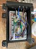
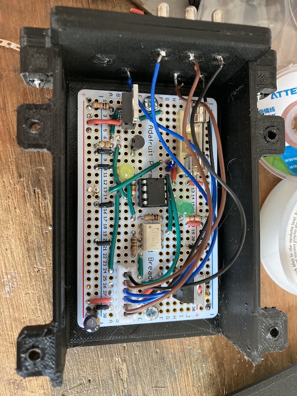
Using an Attiny85, LM7805 5V regulator, and a couple MOSFETs, I wired up my own relay using the stock harness, stock temperature sensor, but matched the glow timing to the newer pencil style plugs. No glow when at temp, 3 seconds when temps are warm, and up to 30s when sub zero. Exact time is calculated by an exponential decay function that I modeled from the service manual literature. You'll notice that my relay has one less pin. Since I don't need a high amperage connection anymore with the outboard relay under the hood, I did away with the #6 or "G" wire. Now, the whole relay is powered from the ignition wire "15" or pin #4. Wire "30" is still used to deactivate glow when cranking starts, and the plugs turn off automatically after the timer has expired.
To finish it off, I 3D printed a four piece housing to hold the pins and perf board. I used PETG as it has held up well in the summer for other projects. PLA is a no-go for summertime temps inside of a car.
I thought about getting a few professionally made PCBs on hand to see if anyone else was interested, but the pins are probably the toughest part to source. I had an old wiper relay sitting around that I pulled them from, but most probably don't.
Anyway, here are some pics.


 12-27-2021, 10:01 PM


 Linear Mode


