

|
|
|
|
|
|
#16
 02-16-2025, 10:00 PM
|
|||
|
|||
|
Also, I have been painting the rear suspension and subframe pieces. Nothing fancy. Just standard paint prep, primer, and Rustoleum Gloss Black. This will be a driver, not a trailer queen.
Decided that since the car only shows 128K miles, and everything I've seen so far supports that number, I am not replacing the factory Bilstein shocks yet. That's an easy task later if needed. I did paint them though. I think this is the final catchup post item: I removed the driveshaft today. I should have waited to buy the parts to renew it, because I discovered that the u-joint has some "notchy" spots in one direction, and evidence of petroleum wetness around the joint. As I understand it, the u-joint is not really serviceable by mere mortals, So now I'm planning to send it off to Driveshaft Specialist of Texas for a complete overhaul. 
|
|
#17
02-18-2025, 10:29 PM
|
|||
|
|||
|
Possible help, put the drive shaft u-joint on a vise, strike the collar at the base near u-joint
5-6 times, with a medium size hammer, check for free movement ,may need to repeat a few times ,move on to others and come back if no success. So far has worked each time.
|
|
#18
02-26-2025, 10:08 PM
|
|||
|
|||
|
Last Friday, I road tripped to Buford, GA for an appointment with C.V. Source. The owner, Jon, allowed by to come by with my axles, and they would *safely* disassemble the Weiss joints (the end that goes into the differential) from the axles so I could take them to a machine shop to get the Quaife modification done. Now that I saw how that comes apart, I might be able to duplicate it, but SURELY would have knackered something, not knowing how it went together and how it should come apart. There were no videos on YT that I could find to explain how it was done, or even what the bare Weiss joint looked like. For your viewing pleasure, a couple of photos:
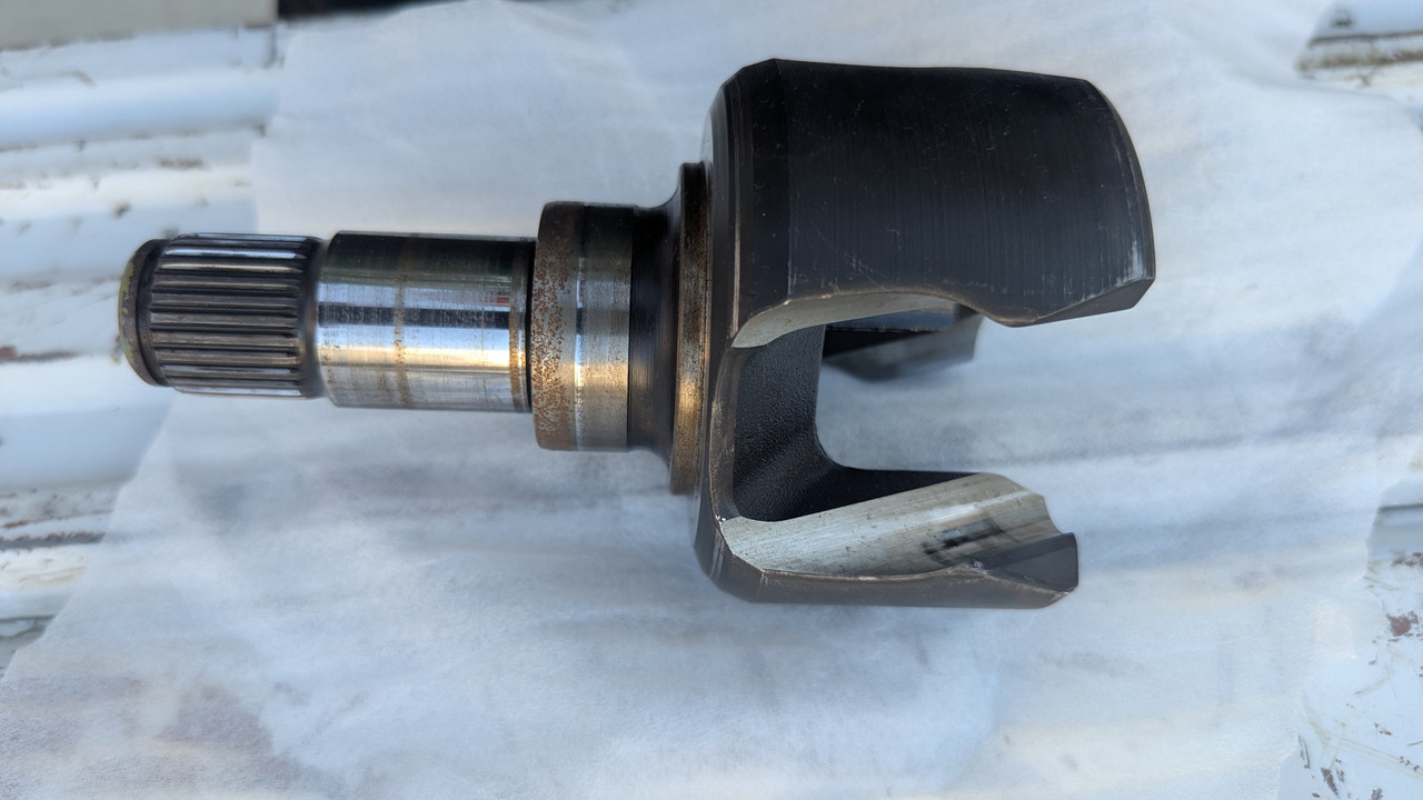 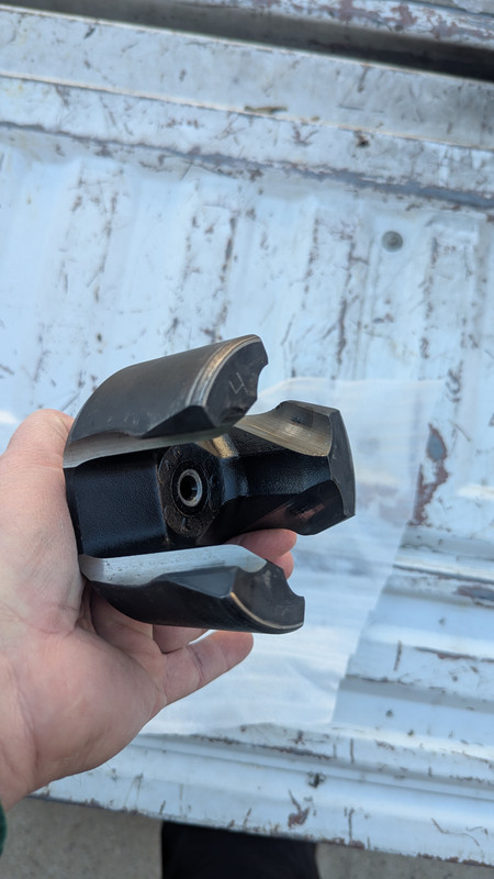 As you can see, and as I hoped, there is a beautiful hole on the inside that is perfect for the CNC shop's lathe to center on. Here is the YT video that led me to C.V. Source. https://youtu.be/mOL4Bv5Ewbk?feature=shared Here is the link to C.V. Source in Buford, GA. https://www.cvsource.com/ I only took one photo at C.V. Source, and it was this one b/c it blew me away. You don't see this much any more, and it impressed me..... 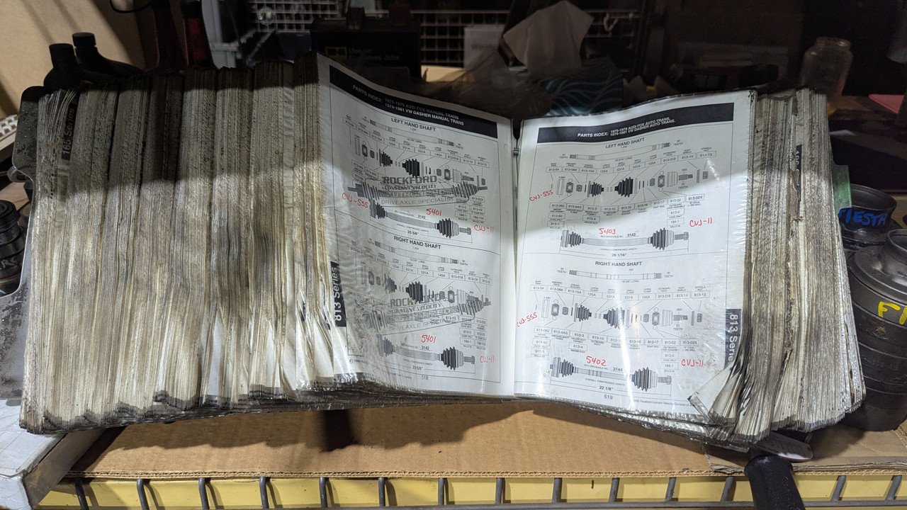 As I approached this tome with awe, and reverently turned the pages, I felt like Gandalf in the basement of Minas Tirith, discovering long forgotten history.... (no sarcasm .. I really thought it was cool)
|
|
#19
02-26-2025, 10:13 PM
|
|||
|
|||
|
Quote:
|
|
#20
02-27-2025, 07:26 PM
|
||||
|
||||
|
Moar progress! Yippee!
__________________
John HAUL AWAY, OR CRUSHED CARS!!! HELP ME keep the cars out of the crusher! A/C Thread "as I ride with my a/c on... I have fond memories of sweaty oily saturdays and spewing R12 into the air. THANKS for all you do! My drivers: 1987 190D 2.5Turbo 1987 560SL convertible 1987 190D 2.5-5SPEED!!!  1987 300TD 2005 Dodge Sprinter 2500 158"WB 1994GMC 2500 6.5Turbo truck... I had to put the ladder somewhere!
|
|
#21
03-09-2025, 11:55 PM
|
|||
|
|||
|
There's been a lot of progress lately!
The replacement driveshaft came in. I ordered it from the best driveshaft company in Nashville. Dude can be a bit of trip. He's like that world class surgeon that is so good you don't care that his bedside manner is gruff. Fair warning. That said, he explained that he doesn't try to rebuild staked driveshafts, but has this rebuilder here in the US he's used for years that he trusts. I paid more that I intended but LOOK AT THAT REPLACEABLE U-JOINT (and it came complete, with centering bushings, and center bearing and bearing mount)!! He says the U-joint is a Spicer 5-153x, allegedly commonly used in Jeep applications. 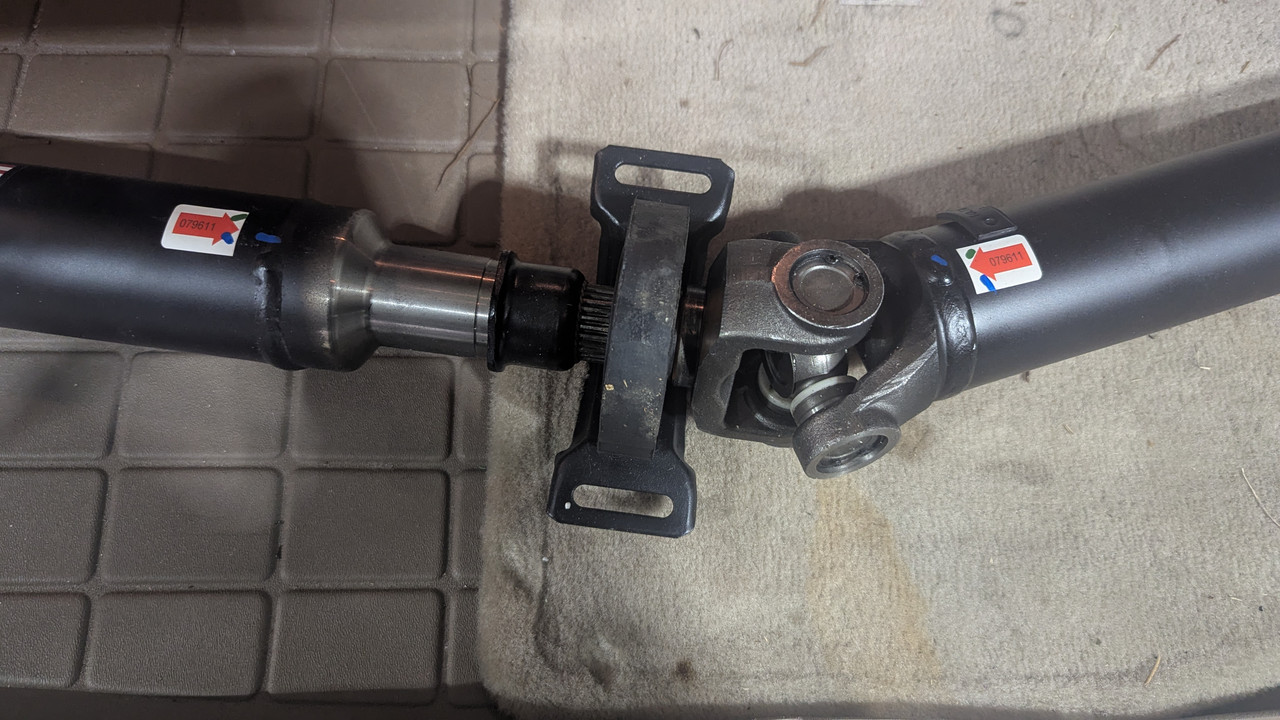 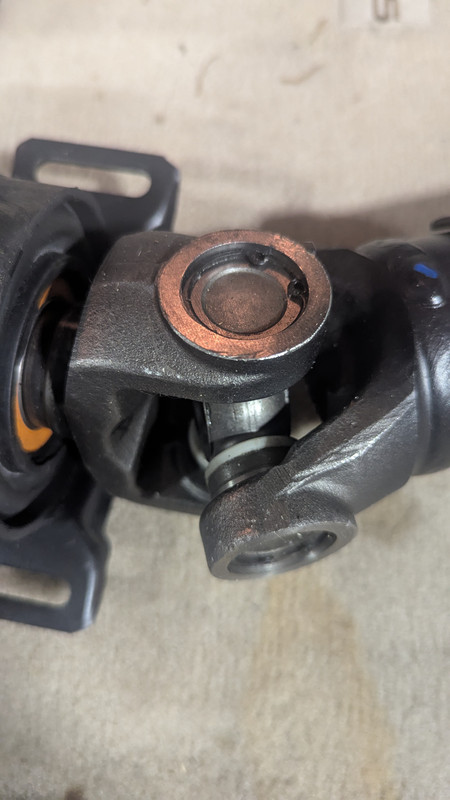 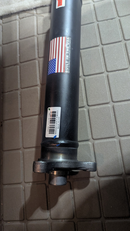 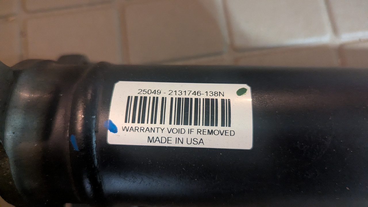 Hamilton Machine Company in Mt. Juliet finished the machine work to make the axles work with Quaife ATB diff. I measured and inspected their work, and it looks good to me! They charged me $300 + tax, but indicated that the next time this needs to be done, it would be less, since they have the setup dialed in. As a reminder, this is what Quaife required: 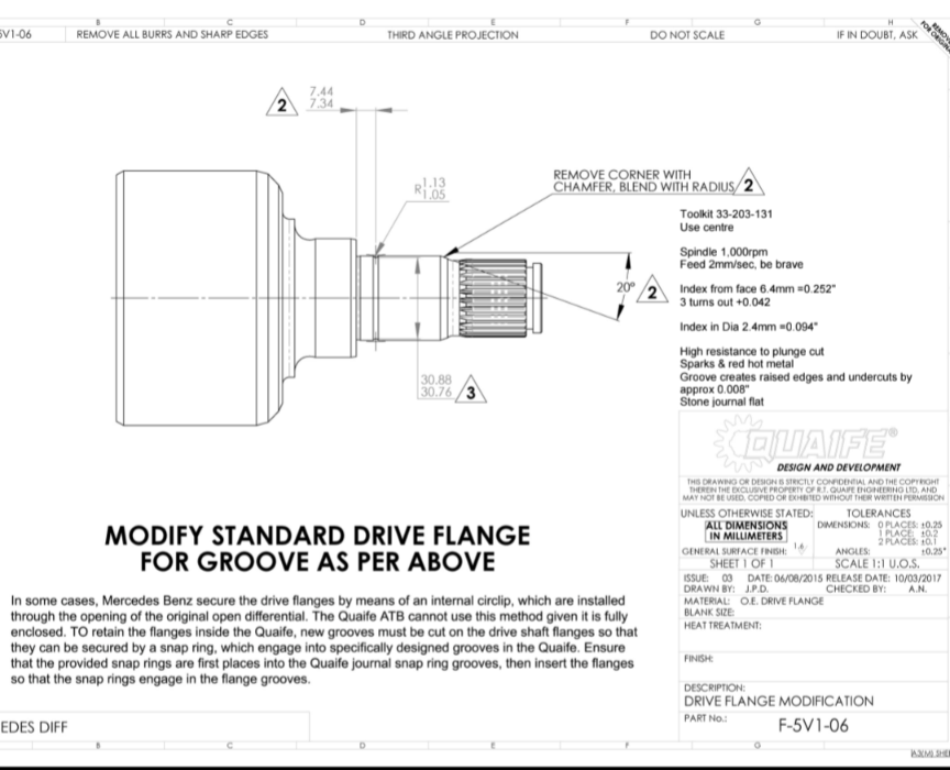 And this is what Hamilton Machine Company produced: 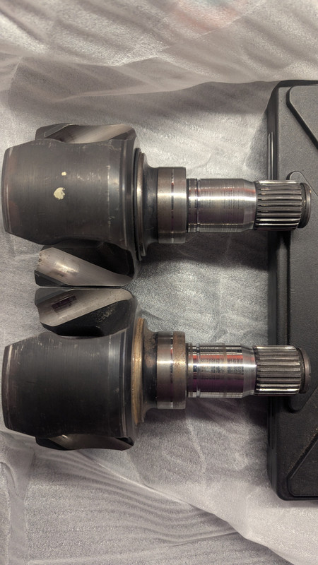 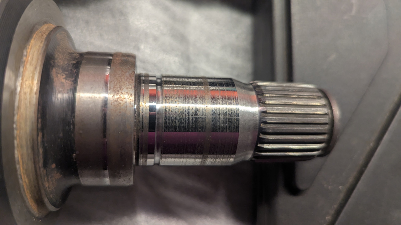 I started in earnest on the differential and carrier. I mocked it up, knowing I'd have to tear it all apart anyway, since the flange/yoke needs to be upgraded to the larger size to match the driveshaft, which will drive replacing the crush sleeve and resetting preload. 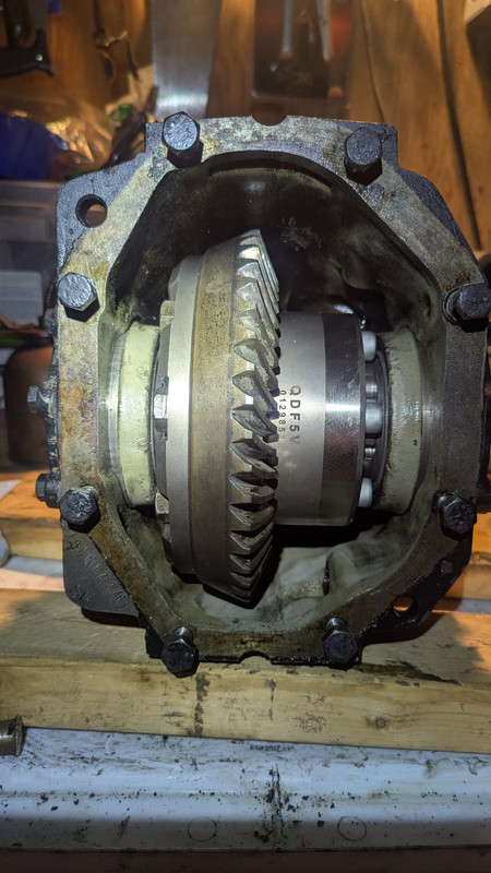 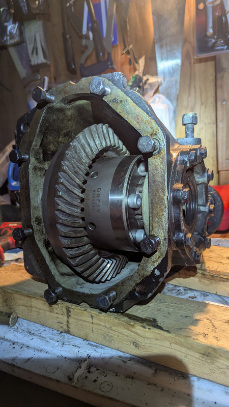 Anyway, the mockup was done in the hope beyond hope that the backlash and gear contact would be perfect without having to source/fab side cap and pinion bearing shims (or "compensating washers" as MB calls them). I measured backlash and found it to be in spec, but on the tight/small side of the spec. Here's what the contact looks like in the mockup: Forward pattern: [IMG] 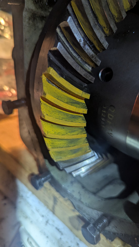 Reverse pattern: 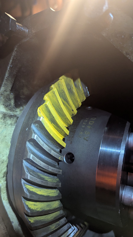 What do you think about the forward contact pattern? Close enough, or should I get to work getting dead on?
|
|
#22
03-10-2025, 12:06 AM
|
|||
|
|||
|
I just realized something.... I bet the axles have to be inserted to keep the crown gear and diff aligned in the carrier. Maybe the contact is better than I think. Or worse, lol.
Well I was going to have to test the compatibility of the machine shop's work with the actual Quaife unit anyway. It will have to wait. I tore it all down and started the process of replacing the pinion crush sleeve, pinion seal and upgrading the yoke to the larger size used by the '85 driveshaft. [That crush washer will not get used until I am sure the backlash and gear contact is as good as I intend to get it.]
|
|
#23
04-06-2025, 08:54 PM
|
|||
|
|||
|
Work on Tuco has been progressing. Most brain-cycles have been dedicated to figuring out how to get the differential adjusted properly to accommodate the new Quaife internals. So many parts, like pinion race shims, are nearly unobtanium now. Good news though, I posted a separate thread about a shim kit I found that I think is a legit, inexpensive alternative to this quandary. https://www.peachparts.com/shopforum/mercedes-benz-sl-discussion-forum/424636-pinion-bearing-shims-alternative-plus-oem-part-numbers.html#post4353820
Meanwhile, I am getting really good at assembling, and disassembling the diff through the adjustment trial and error process. I was frustrated about this until I read that this is *typical* for differentials of this design style. Along with the MB manual, I have been using as guidance: https://www.randysworldwide.com/web_images/pages/Install%20Manuals/YukonKitInstallManual_Complete.pdf Meanwhile, to get some small "wins", I painted the sway bar and sway bar bushing brackets, and installed them with new bushings. 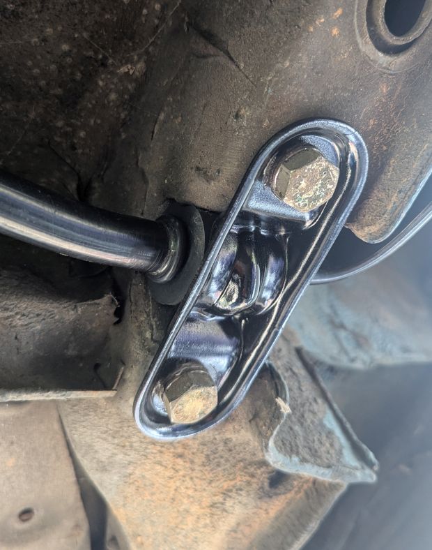 Also, I installed new subframe "bumpers", pictured here next to one of the dry-rotted originals. 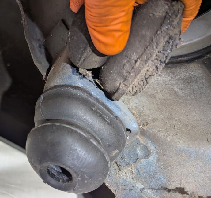
Last edited by lakesurfer; 04-07-2025 at 12:31 AM. Reason: Updated
|
|
#24
06-16-2025, 07:45 PM
|
|||
|
|||
|
Warning: While I am stoked about my Quaife differential, and the support they gave me, that drawing *MAY NOT* exactly show where that groove needs to be on an older MB differential. I will make a brief post about that later in this thread, and a separate detailed post about the whole process with the diff somewhere at some point. Here's the summary:
My axles had spacers between the "shoulder" of the axle and the "spigot" (entry point) of the internal differential unit. In my case, the spacers were about 3 mm thick each, so pretty significant. The axles would NOT insert all the way into the Quaife if the spacers were omitted. It was a matter of where the internal splines were machined, NOT a matter of the axle being too long. The groove location measurement on their original drawing assumed the axle fully inserted into the Quaife. So I had to get a 2nd groove machined that accounted for my spacers. No big deal. It seemed to work just fine with the second groove. Given the vintage nature of my diff, and the rarity of anyone wanting to add an "LSD" function to one, I am grateful that Quaife offered any solution at all, and the quality of their product appears to incredibly well built. I can't wait to drive with it. It might be expecting too much for something custom to be perfectly "plug and play". To their absolute credit, they were absolutely communicative and responsive through the whole discovery process. Again, more details later, but since I was unable to edit the drawing image, I wanted this warning out there.
|
|
#25
06-16-2025, 07:59 PM
|
|||
|
|||
|
In other news, there's been a ton of progress:
**Pinion flange on the 3.46 diff replaced with the larger flange for my prop-shaft. **Quaife diff fully installed, and diff set up with acceptable preloads, contact patterns, and backlash. (Had to tear it down and reassemble the whole thing about 10 times to get it all right. Also had to improvise the shims for both the pinion depth and the R/L side caps since those parts are all almost unobtainium. **Axles machined for the Quaife, and professionally rebuilt by C.V. Source in Buford GA. Awesome!! **Prepped, primed, and painted the 3.46 differential. Discovered that the differential cover is actually aluminum, so I buffed it up a little and left it "shiny". Bought stainless bolts to match, and after market aluminum HEX drain and fill plugs with integrated magnets. They look good, I hate the "allen head" plugs, and love the idea of magnets picking up the trash. **All rear suspension heavy parts de-rusted, prepped, primed, and painted. **Tore down rear bearings. Found good bearings, but bad grease on one side (!!). Cleaned all. Replaced grease (50g/side) and crush sleeve, and torqued to proper amount of play per FSM. **Cleaned and reassembled parking brakes. Original shoes still have plenty of life. **New (rebuilt) rotors, ATE calipers, and brake pads. **Pressed in new bushings for the trailing arms and the subframe mount. **Attached the differential to the subframe with new class 10.9 nylock nuts and lockwashers for good measure. I am very close to final assembly and reinstallation of the rear suspension!! Pictures coming.
|
 |
| Bookmarks |
|
|


 Linear Mode


