

|
|
|
|
|
|
#1
 04-29-2015, 11:39 AM
|
|||
|
|||
|
300d alternator wiring help
i stuffed an 85 turbo diesel motor into an 82 yota 4x4 and will be using the mercedes alternator. There are 3 wires coming out the back, 2 thicker white/red charging wires and a thinner white/blue. I intend to run the charging wires to the battery+/starter connection. Wondering what the white/blue is for? I've read it is a "charging indicator" but does that mean that it is always lit on your display? If i were to splice it with the indicator lamp wire for the cluster in my yota would this mean the battery light would always be "on" while driving, and then only go off if the alternator failed to charge?


|
|
#2
04-29-2015, 12:23 PM
|
|||
|
|||
|
bo:
The wire from the D+ terminal on the alt. (blue/white, changing to blue) will be wired to one side of the charge indicator light of the instrument panel IF that indicator light has 12V+ supplied to the other side with KeyOn. When the key is on, engine off, the light will be on because a ground exists through the alt. diodes. When the engine is running, and the alt, is charging, both sides of the indicator light will be at 12V+, and no current flows, so the light is off. If the indicator is not wired as above, get a diagram for the vehicle, and perhaps we can figure some way to provide charging indication.
|
|
#3
04-29-2015, 12:36 PM
|
|||
|
|||
|
here is the diagram for the stock alternator for a 22r motor. I would be splicing the white/blue with the yellow instrument cluster wire. I would not be using any of the others as they are on the drivers side fender well and it would be much easier to run the red/white wires directly to the battery. So it is my understanding that with "key on" but not running the battery lamp would be on, but once running the blue/white has a positive charge and lamp will be off?
Also just out of curiosity whats the purpose of 2 white/red charging wires? do they produce different fields of AC current? 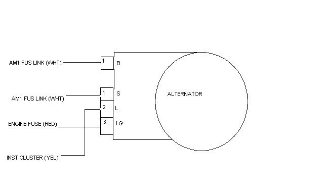
|
|
#4
04-29-2015, 12:55 PM
|
|||
|
|||
|
Quote:
The chassis diagram would be needed to see how the indicator light is wired. You can check for 12V+ at the yellow wire with KeyOn. Your understanding of the light operation is correct. Two red/white wires (B+) are used to provide extra current capacity, rather that using one larger, and less flexible wire.
|
|
#5
04-29-2015, 01:25 PM
|
|||
|
|||
|
You MUST have a light bulb or similar wattage load connected to the alternator "BATT" wire! And the correct wattage bulb ONLY!
The alternator needs an "excitation voltage" to get going and that is provided via the BATT lamp - and the correct current [amperage] is provided when using the correct wattage bulb. Here is technical information on this... Pelican Technical Article: Alternator System Troubleshooting For more, search google.com for the following words... bosch alternator excitation
|
 |
| Bookmarks |
|
|


 Linear Mode


