Quote:
Originally Posted by Mxfrank

You may be confusing thermoswitches and sensors. The three pin device is a thermoswitch, the two paths are either open or closed, depending on temperature. The black one pin device is a sensor, it contains a thermistor which has variable resistance based on temperature. I may be wrong, but I believe the two pin device in your photos is also a thermistor, which supplies a temperature reading to the climate control unit, which in turn controls the fan.
On those cars where the red switch is used, it serves the purpose of completing two circuits. The first circuit will close when engine temperature reaches about 100C. It engages the electric fan at high speed, bypassing the resistor. The second circuit engages at around 105C, and turns off the A/C compressor. There are a couple of versions of this switch, which engage at different ranges.
|
I understand that the blue 2 pin sensor I showed is a thermoswitch. It turns the aux fans at 130C. So you are saying that the red sensor is a thermoswitch for 2 separate circuits then. This doesn't fit the criteria for what I'm trying to do then.
Quote:
Originally Posted by optimusprime
John you look across the top of the block you should see an extra threaded brass plug you can remove to fit the new sensor in to. I use it to bleed the coolant system after a change And the the first sensor in pic is the electric fan clutch
Second is a coolant sensor ACC
Third is just a coolant sensor .
|
The engine I'm working with on this is the CIS M104. It doesn't share the same luxury as the M103 with spare plugs to remove.
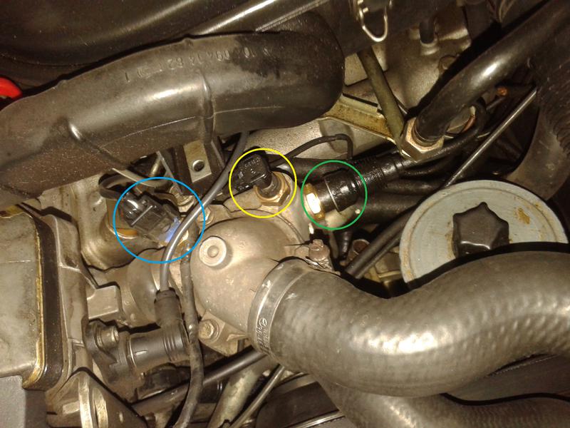
I was hoping to consolidate the blue 2 pin and black single pin sensors into 1 hole with the red sensor, leaving me with a spare hole to add an additional sensor for something else.


 06-06-2018, 06:19 AM


 Threaded Mode


