

|
|
|
|
|
|
#17
 03-19-2011, 11:07 PM
|
|||
|
|||
|
Hi,
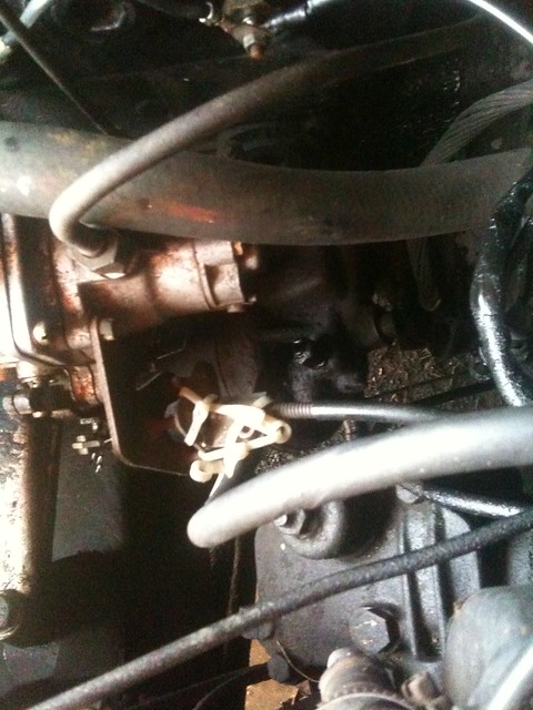
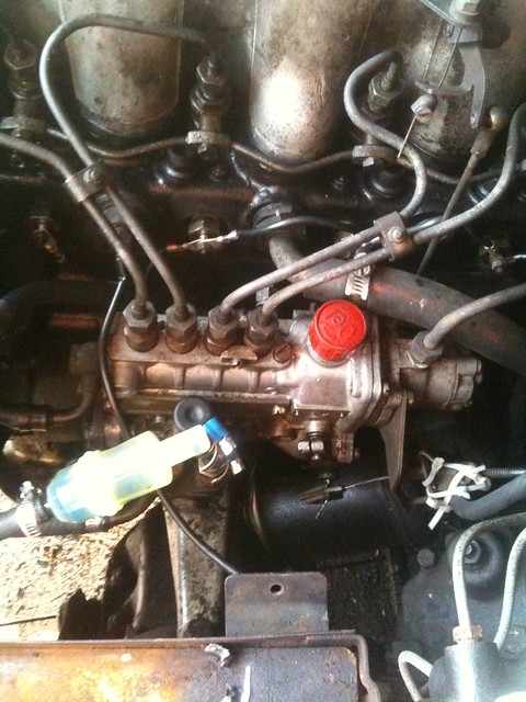
Heres a file answering some important questions: http://www.vintagetest.net/engine/imp/iep73/PCI736293.pdf while setting the idle speed(flat screwdriver on the idle adjust screw on the throttle duct, engine up to oper.temperature), the link between the throttle duct(the control flap shaft actually) and the intermediate V-shaped lever attached on the valve cover(referred to as angle relay lever in the document)should be unhooked. Fast idle speed knob on dashboard turned fully right(low). One sets the idle speed, then proceeds adjusting the levers lengths as described in the document(if needed).Dont pay that much attention to the listed length(XXmm) of the lever that stretches from the angle relay lever to the throttle duct in the end the control flap shaft should rest on the idle speed setting screw and the vertical lever that connects the additional control lever on the IP governor to the angle relay lever should be raised up appr.1mm to be attached. And at last one sets the fast idle speed cable-there should be some minor clearance .See the pic attached. Id start with the easier/cheaper things first-change ALL rubber fuel lines. I see your car still has the original lines with pressed fittings but getting the banjo bolts/fittings from later models should be easy( junkyard, diesel shops etc...plastic lines should be easily obtainable). Id also inspect the small feed hose from the tank for leaks(dealer item, its ends are with different diameters)..and clean the fuel screen in the tank(22mm nut+ socket is enough). If you need access to the tank internals from above, remove the fuel gauge in trunk (plastic cap on trunk floor, unhook the cable, unscrew the small nuts, pull gently the gauge ) The lift pump and the overflow valve should be checked for proper operation. Some threads from the Diesel Discussion: Refreshing the fuel pump on an OM617 (European spec non turbo) your lift pump is different, but utilizes the same valves and o-rings. The valves are very durable, but sometimes sticking crud hinders their proper operation. Id change the o-rings if the lift pumps had never been serviced (now the o-rings are made of viton, green in color and less affected by ULSD or Bio-D).Set of 2 o-rings and 2 valves, Bosch # 2 447 010 044. Now for the trickier part-there is a small o-ring inside of the pump that seals the plunger rod(see Armys pics in the link above-in FP/K22M7 the rod is behind the roller assembly and the o-ring groove is set deeper in the pump body the removal is easy with a large needle, but the install is a fiddly job) when the o-ring wears out, fuel sneaks into the IP internals, diluting the oil or oil from the IP enters the lift pump. Either scenario should be avoided. Again, get the Viton replacement(green).Bosch # 2 440 210 002 You may also want to change the plunger spring ,Bosch #2 444 617 010(same on 300 turbodiesel models-its stronger than the others. Cheap.). All these parts are obtainable from FastLane. Injection pump bypass valve spring OM621 IP uses the same overflow valve. Feel free to check the internals for debris or wear). Great youve upgraded to fast glow plugs and newer style hand pump! Try to find the missing clams for the IP delivery valve nipples. Torque it to 7-8Nm(very gently). Id install another couple of injector lines clamps(reduce vibrations)-I believe there should be 4 altogether! I see some cable ties on the IP lever-have in mind that the cable should be adjusted as described in the document-there should be clearance on both ends of the eye in driving position, so that the lever is not pushed towards Stop (reduced fuel quantity) !!! A note on the diaphragm test-don`t bother unscrewing the control rack end cap and dont expect it to be absolutely tight either, as there is no gasket (ex-factory) on the housing. The initial sucking strength is what counts here IMHO and in several seconds the rack will start moving towards delivery stop even with a brand new diaphragm (but I might be wrong). Its amazing how better the car feels with fuel delivery in order. 
|
|
#18
03-20-2011, 10:25 AM
|
|||
|
|||
|
Vox my friend, you are absolutely amazing. Thank you so very much for taking the time to help me through this. I will be looking into the things you suggested, and will let you know my progress as i have it! Thanks again,
Zach
|
 |
| Bookmarks |
|
|


 Linear Mode


