...better late than never.
I think I've got all the stuff I need to start checking the gearbox.

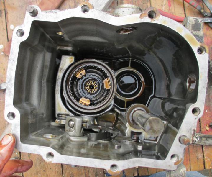
The only damage I can find is on the reverse cog =>

You can see the edges have gone (a bit) on the large cog that's just above the tapered roller bearing in the picture above.
[Trying to provoke the only a stick shift will do crew]
To replace this cog it would not only cost money (!) but I'd have to pull the bearing off of the end of the main shaft. I can't be bothered. It is not as though this is a real gear box => it isn't an automatic transmission where this would matter <= !!!! => manual gearboxes are disposable!
[/Trying to provoke the only a stick shift will do crew]
Despite my anti-manual gearbox-ism the tolerances on these gearboxes are quite impressive. Here's what you are meant to set the parts at

Please note - there are no deep groove ball bearings in my gearbox. This is red herring - ignore this specification if you only have tapered roller bearings.
I have amassed a pretty impressive amount of information regarding how you are meant to strip and rebuild these gearboxes, and I must say that a lot of it is pretty confusing. I find that the Mercedes based literature for the W123 era is much easier to follow - I think this post 1985 documentation is pretty confusing.
I've gotten hold of
717.41X WIS information - not very detailed
717.43X FSM info - slightly different gearboxes to the 717.41X-es
717.44X FSM info - slightly different gearboxes to the 717.41X-es
717.412 information in the W124 Haynes manual
I had a lot of reading to do - but thanks goes to those who helped me find all of this reading material.
It all boils down to the following points
1) The input shaft is only connected to the main shaft via the lay shaft
Here's a picture of the input shaft in the bottom of the gear box
And here's a picture of the main shaft being removed

2) The clearance or end float of the combined input shaft and main shaft and the lay shaft needs to be correct
3) These two clearances are made between the front of the gearbox casing and the intermediate plate => middle casting bit that doesn't exist on the 4 speed gearbox

4) The distance between the 3/4 synchro gear and the intermediate plate is important
5) You are meant to measure this with lots of special tools!
Here's what you are meant to do =>

You dismantle the gearbox and then knock the bearing cups on the front of the gearbox outwards of the casing. You then Install a special tool that allows you turn the shafts and tighten the clearance / end float until there isn't any; you then measure the distance of the bearing cups from the casing with a depth gauge. By measuring the distance of the shim material in the front cover to the cover mating surface you can then work out the clearance - or what the clearance should be.
I don't have this special tool.
I'm not going to buy this special tool - so I had to come up with another plan.