

|
|
|
|
|
|
|
|
#1
 12-27-2009, 11:53 AM
|
|||
|
|||
|
Quote:

|
|
#2
06-05-2011, 12:48 AM
|
|||
|
|||
|
MP3 input.
Great job and you are to be commended for it. To me however it just seems like something I could really screw up (and I'd hate to mess up a classic Becker GP), so I bought an adapter that looks like a cassette tape and has a plug that allows me to plug it into my tape player and then into my MP3. For those of us less technically savvy.

|
|
#3
12-27-2009, 09:29 PM
|
||||
|
||||
|
Very interesting. My '90 and '91 are too much of a PITA to fully rewire to me and this is right up my alley.
__________________
I'm not a doctor, but I'll have a look.  '85 300SD 245k '87 300SDL 251k '90 300SEL 326k Six others from BMW, GM, and Ford. Liberty will not descend to a people; a people must raise themselves to liberty.[/IMG]
|
|
#4
01-10-2010, 09:19 PM
|
|||
|
|||
|
The 612 Unit
I've been wondering how to do this as well.
I have a 612 model of the Becker grand prix, and I opener 'er up and this is what I got: (Sorry for the blur, but it still gets the point across)  Question is, How did you figure out which wire went to/did what? After hours of searching, I tracked down the chip TDA 3410, and according to the only datasheet I could find, I can find out where the outputs are... but one of the outputs goes to a brown wire, the other to a yellow wire. There are two yellow wires, one green, one brown, one red. Seems odd that the outputs would be different colors, and especially odd that one of them would be brown. I was wondering what procedure you used.
|
|
#5
01-11-2010, 04:26 PM
|
|||
|
|||
|
You need to start with a decent datasheet, I can't find much on the TDA3410 myself. I would contact the manufacturer of the chip for a datasheet. Then you need to trace the wire/wires from the outputs of the chip. Also that tape head and chip are on their own seperate board, correct? So it has to be one of the wires connecting that board to everything else.
|
|
#6
01-11-2010, 08:12 PM
|
|||
|
|||
|
Yes, it is a separate board, the tape head itself is on the left. Sorry that the pic was so blurry. I guess I'll try to contact SGS themselves... and done. I sent them an email, but who knows how far that'll get. How bad would it be to just desolder the wires and hook them up at random? (obviously not hooking up the red wire to ground)
I have found plenty of datasheets for the TDA 3420, and that is what I was basing my previous statements on (Those tricky websites pull you in making you think they have what you want, and then do the ol bait 'n switch), how different/similar can they be?
|
|
#7
01-11-2010, 08:53 PM
|
|||
|
|||
|
Quote:
Power up the radio, while you have access to the insides, and measure the wires (I'd reference the ground/negative of the DMM to the brown wire). Then cut them and tap in, you can always go back and solder them back together.
|
|
#8
01-12-2010, 01:18 PM
|
|||
|
|||
|
How did you figure out that the copper prongs would signal that a tape was in the deck? I can't find anything of the sort in mine, except for one small one in the back, but when I push in the head (as if a tape was inserted) I still don't get any power from the red line (it only regestered .16v)
|
|
#9
01-12-2010, 11:44 PM
|
|||
|
|||
|
I figured it out for the most part.
NOTE: all of the below could quite possibly be a lie.
I tested it before finishing up all the soldering and installing it all right, and it seemed to be working perfectly. Then I touched the faceplate. Now my radio won't stay on. It comes on for a split second then turns off again. I'll look at it again later this week, but now I am going to sleep. The problem could be an exposed wire, the things I soldered together, my messing with the faceplate, or all of the above. Until I find out what the problem is, don't try this (not that you would) Alrighty, so I figured it out.. kind of. This is what I did, sequenced Adding AUX to a Becker Grand Prix model 612 Radio First, a warning: DO NOT UNDER ANY CIRCUMSTANCE TRY TO DISASSEMBLE THE FACE PLATE. I DID, AND I SORELY REGRETTED THE WHOLE DAY I SPEND REASSEMBLING IT. 1)Take the radio out  2)Remove the BOTTOM plate, no screws here, the plate can just be pried off  3)Now unscrew the head unit. This is the yellowish thing right in the middle. It is held in by two... nuts? that have slits cut in the top for a flat headed screwdriver  4)De-solder all six (or was it five?) wires to this. There should be a main cluster which has a yellow, a green, a brown, and a red. There is also another yellow wire on there. 5)On that main cluster, the green wire is the ground, the brown wire is the right speaker signal, and the yellow is the left speaker signal. Solder these to whatever thing you want. Make sure to insulate everything, as the red wire is live, and there is no way of knowing when the other wires may become live as well. I do not know this for sure as I never received the datasheet from SGS, but trial and error worked for me, and I checked the lines, no voltage on them, so I would assume they are safe. What I still don't know: How to trick the stereo into thinking there is a cassette in there, when there isn't really one. the copper contact that I mentioned earlier is for rewinding, so that isn't it. I spent a good amount of time looking for a switch or a contact of some kind and found none. I guess I'll just use a tape with a hole drilled through it. If you use a normal tape, without actually removing the tape, there will be a 2 second pause every 60 minutes as the tape switches sides. Last edited by mikethezipper; 01-13-2010 at 12:51 AM.
|
|
#10
10-03-2010, 12:17 PM
|
||||
|
||||
|
Great thread. Converted my 612. I found that you can figure out the wires using an ohm meter between the chassis and the wire. On my radio between chassis ground and the wires it was 5k on yellow, 5k on brown, 10k on red and 1 ohm on green. That suggested L&R were yellow and brown (could be mixed I don't care at this point) and green was ground. Another comment is the DIN connector on the back of the radio. This was for playing the becker CB or phone through the radio, could we go in and toggle tape/ipod this way?
I'm jazzed for now. Good cheap solution.
__________________
79 300TD Old Smokey AKA The Mistake (SOLD) 82 240D stick shift 335k miles (SOLD) 82 300SD 300k miles 85 300D Turbodiesel 170k miles 97 C280 147k miles
|
|
#11
10-03-2010, 12:33 PM
|
||||
|
||||
|
Quote:
-Jason
__________________
1991 350SDL. 230,000 miles (new motor @ 150,000). Blown head gasket  Tesla Model 3. 205,000 miles. Been to 48 states! Past: A fleet of VW TDIs.... including a V10,a Dieselgate Passat, and 2 ECOdiesels. 2014 Cadillac ELR 2013 Fiat 500E.
|
|
#12
10-03-2010, 06:32 PM
|
||||
|
||||
|
More on aux din on back of 612
Ok just checked bay. There is a guy selling a plug kit for this port. I have the cb set from the po and it had a schematic. From what I can read on the circuit it takes one audio out and probably makes mono on both left and right on the radio. eBay seller says he only does mono. Makes sense, I have never heard of stereo cb.
There are other inputs on the plug that look like control lines to toggle the function of the radio. With a lot of tracing I could probably figure out how to get upstream of the mono to stereo circuit and then I could potentially have a control where I put in iPod signal and automatically toggle over. Probably the most efficient way to do it is buy the kit on bay, figure out how it works then figure out how to solder in extra channel. Maybe it would be smarter to just get a modern deck.
__________________
79 300TD Old Smokey AKA The Mistake (SOLD) 82 240D stick shift 335k miles (SOLD) 82 300SD 300k miles 85 300D Turbodiesel 170k miles 97 C280 147k miles
|
|
#13
06-06-2011, 08:52 PM
|
|||
|
|||
|
you could send any of the above mentioned radios to becker www.beckerautosound.com and they could add the aux line.
|
|
#14
06-26-2011, 11:02 PM
|
|||
|
|||
|
Ok so I've opened up mine also and recognized the wires I'd need to cut and resolder. But! I want to make sure I do this right before I risk my only form of audio.
So, I've added a link to my thread and also a picture of how my unit looks. It's a 1432. 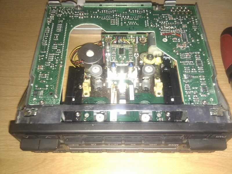 Since there are two green lines can I assume that the Brown one is the ground since it's unusual to have 2 cords for one ground? Which would be the Right and Left? How can I trace these from the board? http://www.mbworld.org/forums/audio-electronics/405825-w124-becker-aux.html#post4733067
__________________
1992 300CE BilsteinSport Vogtland Borla EuroLampsAllAround 3pc18" Staggered BRABUS Monoblock IVs http://i95.photobucket.com/albums/l1...MG00656Sig.jpg FS/FT: 17" OEM 6-Spoke Wheels FS/FT: 16" Lorinser RS-90s FS: W211 Steering Wheel
|
|
#15
07-31-2012, 08:26 PM
|
|||
|
|||
|
Reviving an old thread indeed! @bmwpowere36m3 do you have pictures of the alarm bypass mod that you did and have you found a way to install aux line outs? And... how did you do the mod where the "CR" button controls AUX IN on/off?
__________________
2017 - 1991 Smoke Silver 300ce Tan Interior 2014 - 1993 Blue 190e 2.3 Tan Interior 2012 - 1988 Blue 300ce Grey Interior 2009 - 1989 White 300e Grey Interior Last edited by ebasta; 08-01-2012 at 08:00 PM.
|
 |
| Bookmarks |
|
|


 Hybrid Mode


