

|
|
|
|
|
|
|
|
#1
 08-17-2012, 11:23 PM
|
||||
|
||||
|
Anyone know what would cause the tape to auto reverse a few times then eject the tape? This is the only thing standing in the way of doing the aux in via the tape player. If not I will try and locate the FM inputs and divert them to a switched mini jack.
__________________
Satan creates nothing: he only ruins everything. He does not invent: he tampers. And his followers are no different ~ Archbishop Carlo Maria Viganò 
|
|
#2
10-10-2012, 12:08 AM
|
|||
|
|||
|
ADDED THE PICS BACK
I'll try piecing together a DIY on how I modified my Becker Grand Prix 780 headunit (HU) to accept an auxiliary input (ipod for me). I started with a Becker HU I grabbed from a '89 420SEL at our shop. The first thing I did was verify it was working before proceeding. The HU does not require a CODE, but it features an 'anti-theft' wiring scheme.  I grabbed this picture off another site, the 'anti-theft' feature is the wiring connected to the flat five-pin connector (centered) and the three-prong copper connector (center-bottom). To bypass the 'anti-theft' feature, all that needs to be done is connect ALL the wires out of the flat five-pin connector TO the three-prong copper connector (which is a ground). In essence, you are grounding all the wires in the flat five-pin connector. [SPACE] I'll add a picture later of my modified connector. Now this will prevent the HU from locking when used in another vehicle w/o the 'anti-theft' feature or it allows one to bypass it. Just note that if your HU is already locked, then I believe you need to go to the dealer to get it unlocked. As long as the HU is removed from the car w/o the alarm activated, the HU won't be locked. *IMPORTANT*, the 'anti-theft' feature needs to be bypassed or connected (to a working OE alarm) before powering the HU, or it'll lock. I proceeded to disassemble the unit and clean it throughly. Now onto modifying the HU to accept an auxiliary (line-level) input. Here is my "testing" setup: 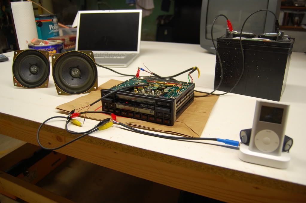 ^ Becker HU, iPod Mini (auxiliary source), and HK (BMW) speakers 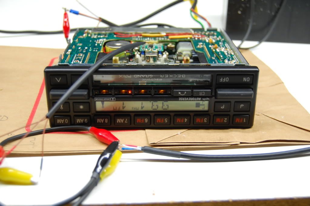 Now onto modifying the cassette section in the HU, thus rendering it unable to play tapes in the future (no loss here  ). ).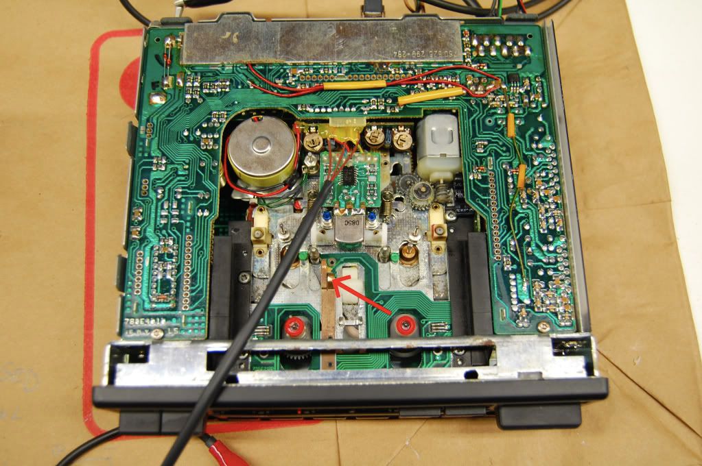 ^ Bottom cover removed First, to allow the HU to "play" your auxiliary source it needs to "think" that it's playing a tape. In the above photo, the RED arrow points to a copper strip. The strip itself is connected to ground, and when a tape is inserted, the strip's tip gets pushed onto a "pad" (directly below it) on the printed circuit board (PCB). Thus grounding the pad on the PCB and activating some sequence in the HU's circuitry. So there are two options: Insert a tape whenever you want to use the auxiliary input or Wire a switch to ground the PCB pad (tricking the HU into "tape mode"). I did the latter and wired the "Tape Selection Button w/Indicator" (seen below) to ground the PCB pad.  Now to actually add the input, I bypassed the original signal that leaves the tape amplifier chip (seen below). 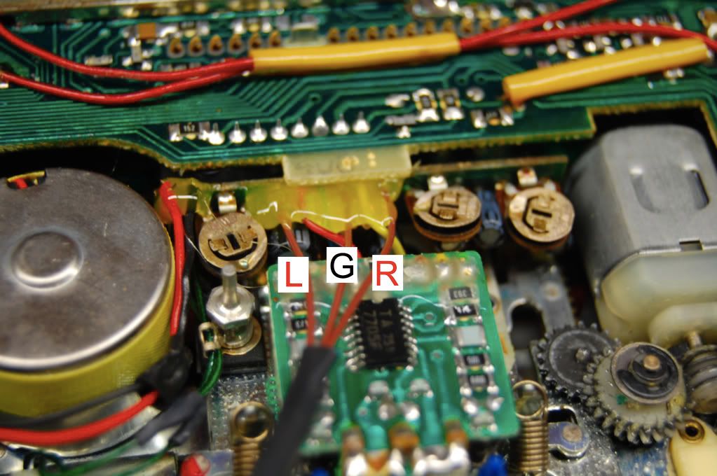 The tape amplifier is the small black chip (centered). I traced the wires back to the HU's circuitry (from the tape amp chip). There are 6 wires that connect the PCB (where the tape amp chip is) to another "vertical" PCB (where the three gold circular trimpots are). Those are the wires we will tie into... The 6 ORIGINAL wires from left to right (looking at the HU like the photo above)are: GREEN, RED, BLUE, BROWN, YELLOW, and GREEN. As labeled in the above photo, the left-most green wire is the "left-channel," the center brown wire is "ground," and the right-most green wire is the "right-channel". Now proceed to cut the three wires (green, brown, green) as close to the tape amp PCB as possible. On their other end (vertical PCB), you'll need to desolder them. Once desoldered, solder in a new set of wires. I'll leave it at that, since you can run a long cable (containing those three wires) out of the HU to a connector of your choice (female 3.5 mm jack, like Becker does for $100) or like me, run them to the HU's back panel (metal) and terminate them to a panel-mount connector. I'll update the connector termination once I get that far. I'm purposely leaving this DIY somewhat general because there are many ways to accomplish this modification. Also the assumption is that any takers will be somewhat adept at figuring things out themselves. I'm more than happy to answer specific questions.[/QUOTE]
__________________
http://i61.photobucket.com/albums/h6...fCSig_WGI1.jpg FS: Closing Shop, Bunch of NOS MB parts for sale
|
|
#3
04-07-2013, 05:06 AM
|
|||
|
|||
|
@bmwpowere36m3 can you provide pictures of the alarm bypass mod that you did and how did you do the mod where the "CR" button controls the jack audio on and the eject turns the jack audio off?? Thanks.
__________________
2017 - 1991 Smoke Silver 300ce Tan Interior 2014 - 1993 Blue 190e 2.3 Tan Interior 2012 - 1988 Blue 300ce Grey Interior 2009 - 1989 White 300e Grey Interior
|
|
#4
12-16-2015, 10:38 AM
|
|||
|
|||
|
Quote:
You can connect them to any ground you like, just the three-prong connector is right there and convenient. The switch... I don't recall the specifics. I think its a momentary ground to begin with, you'd need to verify with a DMM. I cut/scratched one side of the PCB trace away from the switch (NOT the grounded-side). Soldered a wire from the switch (side that is grounded when switch is depressed) to the copper pad/trace on the PCB where the copper strip contacts when a tape is inserted. Basically your grounding the copper PCB pad, tricking the head unit into thinking a tape was inserted. I'll see if I can get some pics.
__________________
http://i61.photobucket.com/albums/h6...fCSig_WGI1.jpg FS: Closing Shop, Bunch of NOS MB parts for sale
|
|
#5
08-29-2013, 10:29 PM
|
|||
|
|||
|
Quote:
Hello all, @bmwpowere36m3 Thank you for sharing. I did fallow your guide and it work like a charm. However, I do have two questions: 1. When I plug a changer into my phone the sound just go crazy, Is there is a way to bypass this ? 2. The Volume is kind of low, am I missing something ? Any help would be much appreciated. Becker Mexico BE1436
|
|
#6
04-13-2014, 02:28 AM
|
|||
|
|||
|
these "instructions" are really vague and kind of bad. id like to see some info on how you wired the chrome tape button to trigger the tape sensor and maybe some feedback that this actually works because it looks on this thread like it doesn't.
does anyone know how its actually done by becker or how the pins on the 6 or 7 pin din outputs on the 612 or 1432 are wired so it can be done diy properly? im trying to get aux into my 780 or find a similar model at junkyard i can get aux into. 
|
|
#7
04-20-2014, 12:46 AM
|
|||
|
|||
|
So I did this modification.
It appears to work ok but my tape player wont hold a tape. When I push down the tape sensor by hand it clicks a few times (like it is trying to turn a tape over) and ejects. The audio from ipod plays for a second before it goes off.. So ironically a prerequisite for this working is that your tape deck has to be functioning correctly... 
|
|
#8
04-20-2014, 03:06 AM
|
|||
|
|||
|
i traced the amp chip TCA 4511 pins 9 and 10 (outputs L and R) to the points on the PCB.
i didnt really care about the tape player because its broken anyway and i was sick of the dumb initial 'instructions' on this thread so i just pulled the wires off and resoldered them to the pcb on these new points. this is how its actually done. dont bother messing with the wires going to the tape amp board. 
|
|
#9
12-16-2015, 10:20 AM
|
|||
|
|||
|
Quote:
1. Likely it's a "ground-loop" issue or "dirty" power source. I've experienced this problem before on projects and made-for-use devices... Without trying it myself or experimenting, the only thing I can say is not to use the charger when playing music (I know, not really an answer). I have the same problem on my motorcycle when I plug is a 12V charger to my iPhone and listen to music thru regular earphones.... sometimes I hear a high-frequency whining. With a 120V wallwart... no issues. 2. Need to turn up the volume on the device.... whether your outputting thru the 3.5mm jack or line-out via the 30-pin connector.
__________________
http://i61.photobucket.com/albums/h6...fCSig_WGI1.jpg FS: Closing Shop, Bunch of NOS MB parts for sale
|
|
#10
12-16-2015, 11:14 PM
|
|||
|
|||
|
ADDED THE PICS BACK AGAIN AND VIDEO [HOSTED BY FORUM, should they shouldn't disappear]
I'll try piecing together a DIY on how I modified my Becker Grand Prix 780 headunit (HU) to accept an auxiliary input (ipod for me). I started with a Becker HU I grabbed from a '89 420SEL at our shop. The first thing I did was verify it was working before proceeding. The HU does not require a CODE, but it features an 'anti-theft' wiring scheme.  I grabbed the above picture off another site, the 'anti-theft' feature is the wiring connected to the flat five-pin connector (#9, centered) and the three-prong copper connector (#10, center-bottom). To bypass the 'anti-theft' feature, all that needs to be done is connect ALL the wires out of the flat five-pin connector TO the three-prong copper connector (which is a ground). In essence, you are grounding all the wires in the flat five-pin connector. There a many ways to do it, such as: use the existing anti-theft harness, tie all the leads together and connect them to the spade connector (w/spring clip) that goes on the three-prong connector.  However, I simply desoldered the wires from the inside of the anti-theft connector (blue arrow), tied them together and soldered them to the wire coming from the three-prong connector (red arrow) all inside the HU. You can see the thin/thick brown wires leading down towards the three-prong connector, that's what I soldered together. Now this will prevent the HU from locking when used in another vehicle w/o the 'anti-theft' feature or it allows one to bypass it. Just note that if your HU is already locked, then I believe you need to go to the dealer to get it unlocked. As long as the HU is removed from the car w/o the alarm activated, the HU won't be locked. *IMPORTANT*, the 'anti-theft' feature needs to be bypassed or connected (to a working OE alarm) before powering the HU, or it'll lock. Here is my "testing" setup: 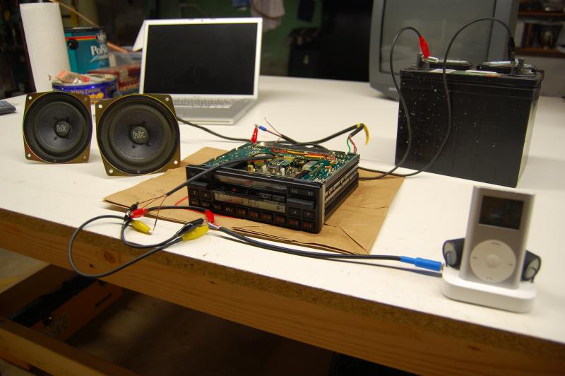 ^ Becker HU, iPod Mini (auxiliary source), and HK (BMW) speakers 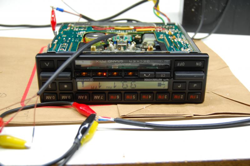
__________________
http://i61.photobucket.com/albums/h6...fCSig_WGI1.jpg FS: Closing Shop, Bunch of NOS MB parts for sale
|
|
#11
12-30-2014, 06:48 AM
|
|||
|
|||
|
Quote:
|
|
#12
12-16-2015, 10:11 AM
|
|||
|
|||
|
Just to revive this thread.... I sold my W123 and found this head unit in my basement (cleaning out).
__________________
http://i61.photobucket.com/albums/h6...fCSig_WGI1.jpg FS: Closing Shop, Bunch of NOS MB parts for sale
|
|
#13
12-16-2015, 10:13 AM
|
|||
|
|||
|
Wow, thread revival.... found this head unit in the basement at doing some cleaning. I sold my W123 and kept this head unit.
__________________
http://i61.photobucket.com/albums/h6...fCSig_WGI1.jpg FS: Closing Shop, Bunch of NOS MB parts for sale
|
|
#14
12-16-2015, 10:41 AM
|
|||
|
|||
|
Lastly
I'll put a thread in the for sale section... but I have no real use for this head unit anymore (like I said I sold my W123 and have no use for it on my W124). So if anyone is interested in it, let me know. Otherwise I'll toss it.
__________________
http://i61.photobucket.com/albums/h6...fCSig_WGI1.jpg FS: Closing Shop, Bunch of NOS MB parts for sale
|
|
#15
12-16-2015, 11:15 PM
|
|||
|
|||
|
Now onto modifying the cassette section in the HU, thus rendering it unable to play tapes in the future (no loss here
). ^ Bottom cover removed First, to allow the HU to "play" your auxiliary source it needs to "think" that it's playing a tape. In the above photo, the red arrow points to a copper strip. The strip itself is connected to ground, and when a tape is inserted, the strip's tip gets pushed onto a "pad" (directly below it) on the printed circuit board (PCB). Thus grounding the pad on the PCB and activating some sequence in the HU's circuitry. So there are two options: Insert a tape whenever you want to use the auxiliary input or Wire a switch to ground the PCB pad (tricking the HU into "tape mode"). I did the latter and wired the "Tape Selection Button w/Indicator" ("CR" button, seen below) to ground the PCB pad.  Now to actually add the input, I bypassed the original signal that leaves the tape amplifier chip (seen below). 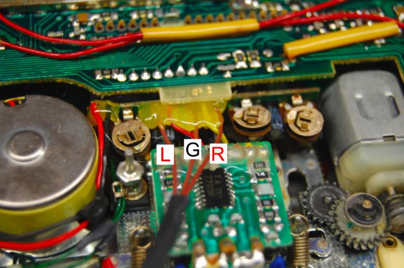 The tape amplifier is the small black chip (centered). I traced the wires back to the HU's circuitry (from the tape amp chip). There are 6 wires that connect the PCB (where the tape amp chip is) to another "vertical" PCB (where the three gold circular trimpots are). Those are the wires we will tie into... The 6 ORIGINAL wires from left to right (looking at the HU like the photo above)are: GREEN, RED, BLUE, BROWN, YELLOW, and GREEN. As labeled in the above photo, the left-most green wire is the "left-channel," the center brown wire is "ground," and the right-most green wire is the "right-channel". Now proceed to cut the three wires (green, brown, green) as close to the tape amp PCB as possible. On their other end (vertical PCB), you'll need to desolder them. Once desoldered, solder in a new set of wires. I'll leave it at that, since you can run a long cable (containing those three wires) out of the HU to a connector of your choice (female 3.5 mm jack, like Becker does) or as I did, run them to the HU's back panel (metal) and terminate them to a panel-mount DIN connector (seen below, green arrow).   Finally here's the headunit in operation: https://www.youtube.com/watch?v=3dB8gZaPe4E I'm purposely leaving this DIY somewhat general because there are many ways to accomplish this modification. Also the assumption is that any takers will be somewhat adept at figuring things out themselves. I'm more than happy to answer specific questions.
__________________
http://i61.photobucket.com/albums/h6...fCSig_WGI1.jpg FS: Closing Shop, Bunch of NOS MB parts for sale Last edited by bmwpowere36m3; 12-17-2015 at 09:48 AM.
|
 |
| Bookmarks |
|
|


 Hybrid Mode


