

|
|
|
|
|
|
#1
 01-19-2010, 06:46 PM
|
||||
|
||||
|
How-to: Disable alarm on a 1993+ W124
This is my write-up for those people who have a funky alarm like mine. I have been putting this off for a while now, but decided to tackle it since i had the cluster out for some other work....
The problem: alarm goes-on when i unlock the car from the driver's door. Solution: Disable the alarm. You can try to fix it, but i understand it will cost a fortune, and too much of a headache for me. Besides, i don't need it !!! Step 1: Disconnect the car battery so that the alarm does not go-off, or you get hit by an airbag while removing the cluster. Step 2: Locate the alarm. In my case, it is under the passenger's feet. remove the floor mat and the foam-backed carpet piece. Unbolt the bolt holding the black plate in place. The alarm is the black box on the left with two big plugs going into it (second picture). 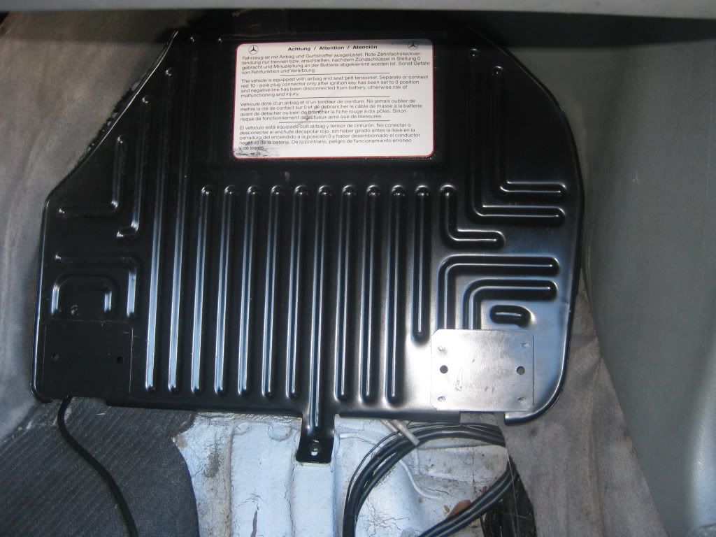 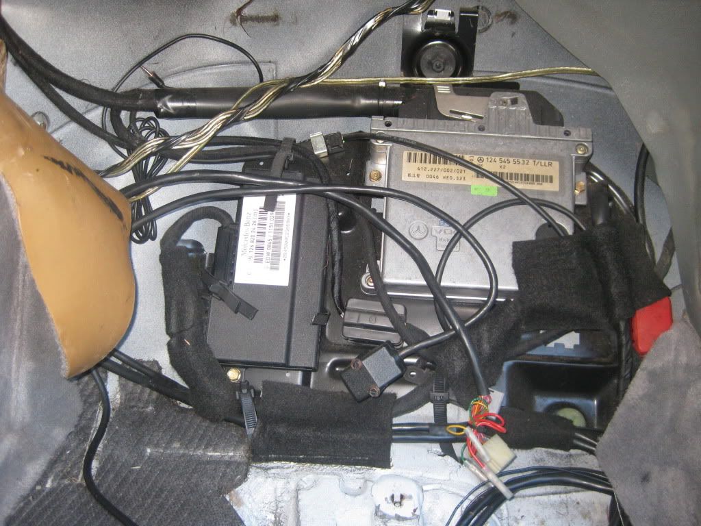 Step 3: Unplug those big plugs. On pre 1993 cars, this should be sufficient to disable the car. Not the case though for 1993+ cars as they have an immobilizer feature that is triggered when the alarm is disabled. so my car would not start after unplugging those two plugs. 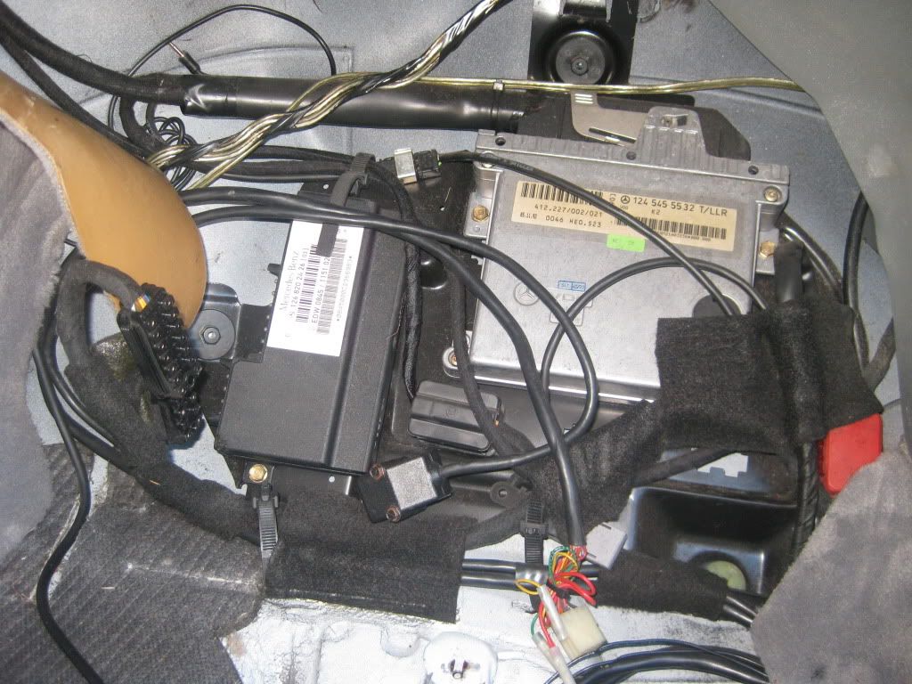 Step 4: You have to find the relay with the name k38. It is located under the instrument cluster. by jumpering this relay, you will be able to by-pass the immobilizer, and have a fully functional car without the alarm. So proceed to removing the instrument cluster as seen below, that is the nastiest part of the job as that thing is tricky....in the picture, the cluster is removed 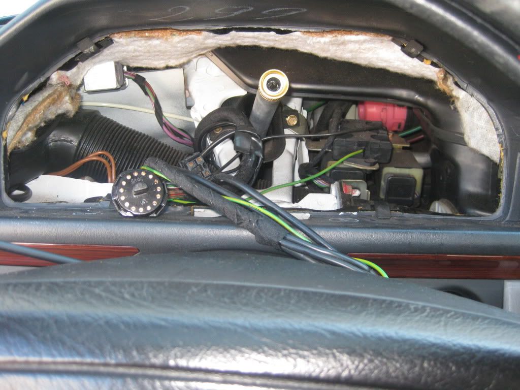 Step 5: Locate the k38 relay. it is in the upper left corner of the cluster space. it is shiny silver in color on my car....pull it out by hand- easy!!   Step 6: in order to bypass the immobilizer feature, you need to jumper pins 30 and 87 on the relay, see the picture below. I ran a copper wire between the two pins. Make sure the wire is as flat as possible so that the relay seats properly 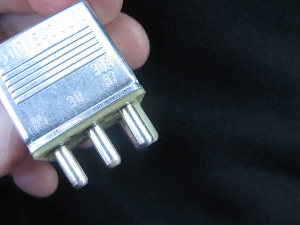 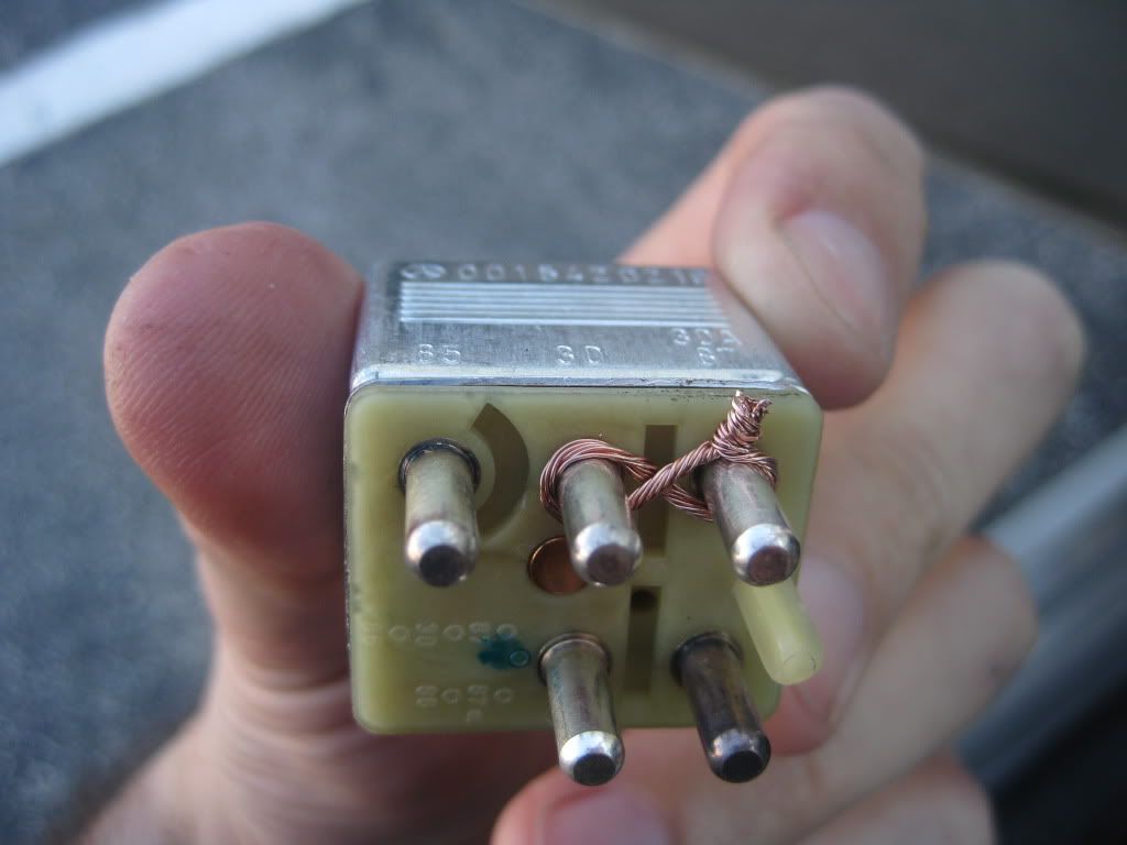 Step 7: put the relay back in place. connect the battery without tightening the terminal. try to start the car, if it starts, remove battery terminal and install cluster. Step 8: tighten battery terminal, and enjoy your car with no annoying alarm !!!!!  Easy job over all. the hardest part was removing the cluster..... Easy job over all. the hardest part was removing the cluster.....Good Luck, Thanks for the help with this guys!!!
__________________
1993 300E, 2.8 M104 ..... Last edited by whunter; 01-21-2010 at 03:50 PM. Reason: attached pictures 
|
|
#2
01-19-2010, 08:14 PM
|
||||
|
||||
|
Very nice description and pictures. the alarm was giving me a problem on my 400e, so I disconencted it and the car wouldn't start. I tapped the alarm module (you know like you used to tap the tv when the picture shrank, or got squiggly) and it's worked fine since then. (Probably just reseating the connector took care of the problem.)
I would imagine that jumpering the purple wire to the purble/green wire would accomplish the same thing. Now you can remove the relay and little the car up a little.  Or put a kill switch in by cutting the red wire and wiring to +12 via a toggle switch, or secondary key. Which got me to thinking, why not find the wire coming out of the alarm that triggers the K38 relay? Tie it to ACC and be done. No need for cluster removal. 
__________________
Closing the store Benzbonz.biz on your smart phone or tablet.
|
|
#3
01-19-2010, 09:02 PM
|
||||
|
||||
|
Quote:
I liked to do it this way in case the next owner decides to fix the alarm correctly...if i it gives me trouble, i will make it more permanent...The reason for this write-up is to document in pictures the wonderful advice given to me here, and to help some other people also who might be unsure about how to do this  This thread is where i got the info from, this is such a great forum.. 95 E320 - Alarm goes off for no reason Special thanks to Kestas and others for their help on this
__________________
1993 300E, 2.8 M104 ..... Last edited by whunter; 01-21-2010 at 03:52 PM. Reason: attached remaining pictures from post 1
|
|
#5
01-20-2010, 06:32 PM
|
||||
|
||||
|
Awesome latief, you da man. What was the problem with the odometer?
Also - I do believe that one cause of the alarm problem you are having is the vacuum door lock actuator. I have the same alarm problem you do but mine is intermittent. My door lock vacuum actuator is dodgy anyway so I am replacing that first and then we'll see if that fixes the alarm. Once you get your trans fixed, with all this other stuff you've done, your car should be in pretty fine fettle 
|
|
#6
01-20-2010, 07:05 PM
|
||||
|
||||
|
Quote:
__________________
RIP: 80 300SD RIP: 79 450SEL 2002 E430 4matic (212,000km) 2002 ML500 'sport'  ____________________________ FACEBOOK: PANZER450
|
|
#7
01-20-2010, 07:18 PM
|
||||
|
||||
|
Quote:
__________________
1993 300E, 2.8 M104 .....
|
|
#8
01-20-2010, 07:23 PM
|
||||
|
||||
|
Quote:
Hopefully, it will not catch fire as Panzer said, The Odometer stopped working for a day after i reset the trip repeatedly while driving. i did not get the memo about not doing that  thanks,
__________________
1993 300E, 2.8 M104 .....
|
|
#9
01-20-2010, 11:34 PM
|
||||
|
||||
|
Well, in my instance, I was powering lights, so there was alot of current, I imagine with an alarm system there wouldn't be much current. and I see it's the 30x pins jumped, that shouldn't be trouble some, just eliminates the NO/NC functioning.
__________________
RIP: 80 300SD RIP: 79 450SEL 2002 E430 4matic (212,000km) 2002 ML500 'sport' ____________________________ FACEBOOK: PANZER450
|
|
#10
01-20-2010, 11:58 PM
|
||||
|
||||
|
Quote:
__________________
1993 300E, 2.8 M104 ..... Last edited by latief; 01-21-2010 at 09:46 AM.
|
|
#12
01-21-2010, 05:48 AM
|
|||
|
|||
|
Quote:
__________________
1993 400E, 256,000 miles (totaled) 1994 E420, 200,000+ miles 1995 E420, 201,000 miles
|
|
#13
01-21-2010, 07:45 AM
|
|||
|
|||
|
Quote:
|
|
#14
01-21-2010, 09:42 AM
|
||||
|
||||
|
Quote:
 See here.... http://www.benzworld.org/forums/w124-e-ce-d-td-class/1495093-odometer-not-working-question-picture.html
__________________
1993 300E, 2.8 M104 .....
|
|
#15
01-21-2010, 06:19 PM
|
|||
|
|||
|
Actually, both the odometer and trip meter are inop, so maybe the gear in the picture is responsible. Thanks.
__________________
1993 400E, 256,000 miles (totaled) 1994 E420, 200,000+ miles 1995 E420, 201,000 miles
|
 |
| Bookmarks |
|
|


 Linear Mode


