

|
|
|
|
|
|
#1
 05-28-2011, 08:07 AM
|
||||
|
||||
|
Guess what I'm up to... :)
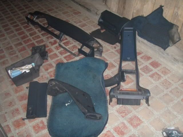 hmmmmmm...
__________________
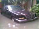 85 190E 2.3(SOLD) 86 230E (-->300D) sold 87 300D (-->300TD) sold 68 250S w/ a 615 and manual tranny (RIP) 87 300TD (SOLD) 95 S280 "The KRAKEN" (Turbo 2.9 602 transplant) traded 86 190E 2.3... current project 
|
| Bookmarks |
|
|


 Threaded Mode


