

|
|
|
|
|
|
|||||||
 |
|
|
LinkBack

|
Thread Tools
|
Display Modes
|
|
#16
 03-07-2014, 08:09 AM
|
||||
|
||||
|
Quote:
Quote:
__________________
1992 W201 190E 1.8 171,000 km - Daily driver 1981 W123 300D ~ 100,000 miles / 160,000 km - project car stripped to the bone 1965 Land Rover Series 2a Station Wagon CIS recovery therapy! 1961 Volvo PV544 Bare metal rat rod-ish thing I'm here to chat about cars and to help others - I'm not here "to always be right" like an internet warrior  Don't leave that there - I'll take it to bits! 
|
|
#17
03-07-2014, 10:41 AM
|
||||
|
||||
|
Quote:
Stretch, on the last page of FSM 07.1- 010 operation injection pump with governor, can you translate the labels in the timing diagram? Some of them are in German I think. http://mercedes.thatchermathias.com/w123CD2/Program/Engine/617/07_1-010.pdf
__________________
85 300D turbo pristine w 157k when purchased 167,870 July 2025 83 300 D turbo 297K runs great. SOLD! 83 240D 4 spd manual- parted out then junked
|
|
#18
03-07-2014, 09:09 PM
|
||||
|
||||
|
If I'm understanding your project correctly, you're attempting to emulate a gas engine timing system with a diesel. You've been able to use a VR sensor to trigger a Xenon timing light on the desk. The plan is to use the IP as a trigger wheel and drive the timing light to read the timing on the front pulley. The tang on the IP you're attempting to read should read 15 degrees ADC if the timing is correct. Is that correct?
In thinking about the system I wonder if it is possible to use either a piezo pressure sensor or maybe even a piezo knock sensor as a trigger event for the timing light. The commercial systems use some kind of a clamp on the injector line that read the expansion of the injector line as pressure to trigger the timing function... at least that's the way I understand their operation. That would take a pretty sensitive sensor to read the tiny bit of movement of the line wall. I'm wondering if it might be possible to create a more responsive and cheaper system that would use a high pressure piezo sensor or maybe even a knock sensor. What I'm thinking about is two sections of stock injector lines (red) connected at a block of aluminum, brass or steel to the #1 injector outlet of the IP. The green connectors in the below image are modified fittings from the IP. I've made a bunch of these fittings for use in a pop tester - metric injector fittings on one end and 1/4NPT on the other to make fabricating a connector block extremely simple. Reading the signal should be pretty easy, although I think it would be a rising edge rather than a falling edge you'd be looking for. If you can use a knock sensor they're dirt cheap - a pressure sensor, maybe not so much. 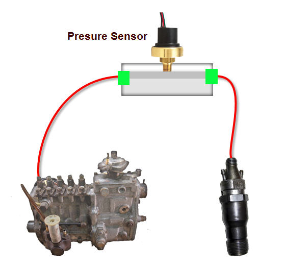 I may be completely off base with this idea, but who knows, maybe it would trigger some other options to accomplish the goal. If you're using a VR sensor, you can use almost anything that would fit. RPM and speed sensors off the MB, cam position sensors, wheel speed sensors, and so forth.
__________________
Current Stable
|
|
#19
03-08-2014, 02:10 AM
|
||||
|
||||
|
Quote:
v.OT means before TDC n.OT means after TDC Was that the bit you wanted?
__________________
1992 W201 190E 1.8 171,000 km - Daily driver 1981 W123 300D ~ 100,000 miles / 160,000 km - project car stripped to the bone 1965 Land Rover Series 2a Station Wagon CIS recovery therapy! 1961 Volvo PV544 Bare metal rat rod-ish thing I'm here to chat about cars and to help others - I'm not here "to always be right" like an internet warrior Don't leave that there - I'll take it to bits!
|
|
#20
03-08-2014, 02:13 AM
|
||||
|
||||
|
Quote:
Injector line pulse frequency - help needed The difference however is to not arse about putting in pressure transducers (you'd have to bleed) but to measure the elastic deformation of the injector line (clip on clip off)
__________________
1992 W201 190E 1.8 171,000 km - Daily driver 1981 W123 300D ~ 100,000 miles / 160,000 km - project car stripped to the bone 1965 Land Rover Series 2a Station Wagon CIS recovery therapy! 1961 Volvo PV544 Bare metal rat rod-ish thing I'm here to chat about cars and to help others - I'm not here "to always be right" like an internet warrior Don't leave that there - I'll take it to bits!
|
|
#21
03-08-2014, 09:26 AM
|
|||
|
|||
|
Quote:
Instead of a two-part hard line, a small fitting for the piezo could be machined that either screws onto the injector, or the IP fitting; and the hard line screws onto the fitting. You would just leave it always in place.
__________________
. 1st MBz: 1982 300SD 2nd MBz: 1987 300SDL 3rd MBz: 1995 S420 4th MBz: 1987 190DT 5th MBz: 1984 300SD w/1983 300DT engine 6th MBz: 1999 C230k I'm 3rd owner, got it w/57,235 miles. and manages Mom's 2007 R320 CDI
|
|
#22
03-08-2014, 09:29 AM
|
||||
|
||||
|
Quote:
On the top chart, below the left most vertical scale line @ 24 deg v. OT, Is the = sign in "OT-I = RI = FB - P" meant to be used as a formula? What does "FB" and "P" stand for? Is the "-" a dash?
__________________
85 300D turbo pristine w 157k when purchased 167,870 July 2025 83 300 D turbo 297K runs great. SOLD! 83 240D 4 spd manual- parted out then junked
|
|
#23
03-08-2014, 01:36 PM
|
||||
|
||||
|
Quote:
__________________
1992 W201 190E 1.8 171,000 km - Daily driver 1981 W123 300D ~ 100,000 miles / 160,000 km - project car stripped to the bone 1965 Land Rover Series 2a Station Wagon CIS recovery therapy! 1961 Volvo PV544 Bare metal rat rod-ish thing I'm here to chat about cars and to help others - I'm not here "to always be right" like an internet warrior Don't leave that there - I'll take it to bits!
|
|
#24
03-09-2014, 05:15 PM
|
||||
|
||||
|
Quote:
__________________
85 300D turbo pristine w 157k when purchased 167,870 July 2025 83 300 D turbo 297K runs great. SOLD! 83 240D 4 spd manual- parted out then junked
|
|
#25
03-09-2014, 05:23 PM
|
||||
|
||||
|
Bump
__________________
John HAUL AWAY, OR CRUSHED CARS!!! HELP ME keep the cars out of the crusher! A/C Thread "as I ride with my a/c on... I have fond memories of sweaty oily saturdays and spewing R12 into the air. THANKS for all you do! My drivers: 1987 190D 2.5Turbo 1987 560SL convertible 1987 190D 2.5-5SPEED!!!  1987 300TD 2005 Dodge Sprinter 2500 158"WB 1994GMC 2500 6.5Turbo truck... I had to put the ladder somewhere!
|
|
#26
03-09-2014, 06:08 PM
|
||||
|
||||
|
Quote:
I think it should be ignored.
__________________
1992 W201 190E 1.8 171,000 km - Daily driver 1981 W123 300D ~ 100,000 miles / 160,000 km - project car stripped to the bone 1965 Land Rover Series 2a Station Wagon CIS recovery therapy! 1961 Volvo PV544 Bare metal rat rod-ish thing I'm here to chat about cars and to help others - I'm not here "to always be right" like an internet warrior Don't leave that there - I'll take it to bits!
|
|
#27
03-09-2014, 06:14 PM
|
||||
|
||||
|
Quote:
__________________
85 300D turbo pristine w 157k when purchased 167,870 July 2025 83 300 D turbo 297K runs great. SOLD! 83 240D 4 spd manual- parted out then junked
|
|
#28
03-10-2014, 04:34 AM
|
||||
|
||||
|
I don't know what it is - may be they were trying to figure something out.
__________________
1992 W201 190E 1.8 171,000 km - Daily driver 1981 W123 300D ~ 100,000 miles / 160,000 km - project car stripped to the bone 1965 Land Rover Series 2a Station Wagon CIS recovery therapy! 1961 Volvo PV544 Bare metal rat rod-ish thing I'm here to chat about cars and to help others - I'm not here "to always be right" like an internet warrior Don't leave that there - I'll take it to bits!
|
|
#29
03-10-2014, 05:24 AM
|
|||
|
|||
|
you know...
you've got something really interesting going on when Roy is following your thread! Yeah, this one is most interesting!
__________________
Dedicated to the preservation of antique Mercedes Benz's, one rusty ol' bucket of bolts at a time!
|
|
| Bookmarks |
|
|


 Linear Mode


